EP1134321A2 - Ventileinrichtung mit Bedienelement - Google Patents
Ventileinrichtung mit Bedienelement Download PDFInfo
- Publication number
- EP1134321A2 EP1134321A2 EP01104840A EP01104840A EP1134321A2 EP 1134321 A2 EP1134321 A2 EP 1134321A2 EP 01104840 A EP01104840 A EP 01104840A EP 01104840 A EP01104840 A EP 01104840A EP 1134321 A2 EP1134321 A2 EP 1134321A2
- Authority
- EP
- European Patent Office
- Prior art keywords
- housing
- valve device
- spring
- catch
- sanitary valve
- Prior art date
- Legal status (The legal status is an assumption and is not a legal conclusion. Google has not performed a legal analysis and makes no representation as to the accuracy of the status listed.)
- Withdrawn
Links
Images



Classifications
-
- E—FIXED CONSTRUCTIONS
- E03—WATER SUPPLY; SEWERAGE
- E03C—DOMESTIC PLUMBING INSTALLATIONS FOR FRESH WATER OR WASTE WATER; SINKS
- E03C1/00—Domestic plumbing installations for fresh water or waste water; Sinks
- E03C1/12—Plumbing installations for waste water; Basins or fountains connected thereto; Sinks
- E03C1/22—Outlet devices mounted in basins, baths, or sinks
- E03C1/23—Outlet devices mounted in basins, baths, or sinks with mechanical closure mechanisms
- E03C1/2302—Outlet devices mounted in basins, baths, or sinks with mechanical closure mechanisms the actuation force being transmitted to the plug via rigid elements
-
- E—FIXED CONSTRUCTIONS
- E03—WATER SUPPLY; SEWERAGE
- E03C—DOMESTIC PLUMBING INSTALLATIONS FOR FRESH WATER OR WASTE WATER; SINKS
- E03C1/00—Domestic plumbing installations for fresh water or waste water; Sinks
- E03C1/12—Plumbing installations for waste water; Basins or fountains connected thereto; Sinks
- E03C1/22—Outlet devices mounted in basins, baths, or sinks
- E03C1/23—Outlet devices mounted in basins, baths, or sinks with mechanical closure mechanisms
Definitions
- the invention relates to a sanitary valve device with a housing, preferably valve housing, and a operating element that can be actuated from the outside thereof, that via a transmission link led out of the housing with a sealing plug to be operated a drain valve is connected.
- Such a valve device is known from German Patent 11 91 305.
- an eccentric lever is provided in a transverse bore of the battery body, which projects radially out of the body with a handle.
- a cavity is provided in the battery body, into which a linkage connected to a stopper of a washbasin is inserted, the linkage being connected to the eccentric lever by an eye formed at the end of the linkage, so that the user can turn the stopper into his by rotating the handle Open or closed position can be brought.
- Such an eccentric lever is relatively complex and requires a relatively large amount of space in the valve body. In addition, the relatively large design of the eccentric lever can disrupt the overall picture of the sanitary fitting.
- this object is achieved in that the sealing plug can be pressed into its closed position by a user against the force of a spring, a latching device for securing the closed position of the sealing plug being provided in the housing, which can be released with an operating element.
- FIGS. 1 and 2 it is a in a housing 1 concealed mixing and shut-off valve for cold and hot water, the cold and Hot water above - not shown in the drawing - Connection lines are inserted into the housing 1.
- At the mixing and shut-off valve can in known Way with an operating handle 15 in a first degree of freedom the flow rate and in a second Degree of freedom the mixing ratio of the inflowing Cold and hot water can be set.
- This in mixed water generated by the mixing and shut-off valve is in via an outlet pipe 14 as a free jet Basin - not shown in the drawing - one Washstand dispensed.
- a drain valve 20 In the bottom of the pool is in known a drain valve 20 arranged and with a drain pipe - not in the drawing shown - connected.
- a sealing plug 2 is arranged, which as a Linkage formed transmission link 3 in the Closed or open position is held.
- the transmission member 3 is inserted into the housing 1 or the fitting body from the fastening side on the wash basin into a receiving space 10.
- a tension spring 4 is arranged in the receiving space 10, which is fastened on the one hand to the bottom of the receiving space 10 and on the other hand to the end region of the transmission element 3 designed as a linkage.
- the sealing plug 2 is thus held by the spring 4 with the aid of the transmission member 3 in its open position, as can be seen in FIG. 2.
- the water emerging from the outlet pipe 14 thus passes through the open drain valve 20 into the waste water line, not shown in the drawing. If the drain valve 20 is to be closed, the user pushes the sealing plug 2 from its position shown in FIG. 2 by an axial movement in the direction of the arrow in FIG.
- a latching device 5 is provided, with which the drain valve 20 is held in its closed position.
- a catch 51 is formed in a radial bore 12 in the housing 1 on a radial rod 53.
- the radial rod 53 carries an operating element 50 in the form of a push button or a push button at the opposite end region.
- the catch 51 is pressed into its detent position by a spring 52, preferably a plate spring.
- the catch 51 is provided with an inclined surface, so that when the transmission member 3 is inserted into the receiving space 10, the catch 51 is deflected radially against the force of the spring 52 and then engages in a case 54 designed as an annular groove, as shown in FIG.
- Fig. 3 and 4 of the drawing is different from the above described in that the spring 4 is not in the receiving space 10 of the housing 1, but below one Dashboard of a washstand 6 as a compression spring the transmission link 3 designed as a linkage is arranged.
- One end region of the spring 4 is supported on the underside of the washbasin 6, while the other end of the spring 4 with the transmission link designed as a linkage 3 is connected.
- FIG. 5 of the drawing shows a further exemplary embodiment with the aid of a water outlet valve, which is shown in part and is mounted on a washstand 6.
- An insert 11 is arranged in the housing 1, the housing 1 being connected in a known manner to a washstand 6 in the region of an opening 60 by means of a fastening bolt 13.
- a receiving space 10 extends from the bottom of the housing 1 into the insert 11.
- a guide sleeve 31 is arranged axially fixed in the receiving space 10.
- the transmission element 3, which is designed as a linkage, is inserted into the guide sleeve 31 and connected to a head piece 30.
- a catch 51 which is pressed in the latching direction by a spring 52 and is designed as a cylindrical pin.
- the drain valve In the position of the transmission member 3 shown in FIG. 5, the drain valve is in its open position, as shown in FIG. 3 in accordance with the previous embodiment. If the user now presses the sealing plug 2 into its closed position in the drain valve 20, the transmission member 3 is simultaneously pushed into the sleeve 31 against the force of the spring 4 until the catch 51 engages in the radial bore 12 formed on the insert 11 and in this case the radial rod 53 is pushed out of the housing 1 by the control element 50 to a small extent and thereby engages in this position, so that the drain valve 20 remains in its closed position.
- Fig. 6 is finally a modified to Fig. 5 Embodiment shown, the transmission member 3 as a linkage in a tubular Fastening bolt 13 from the housing 1 is brought out.
- a guide sleeve 31 is here the receiving space 10 in the insert 11 with a guide slot 111.
- the transmission link is designed as a linkage.
- a linkage can also be a Bowden cable or another suitable means can be provided.
Landscapes
- Engineering & Computer Science (AREA)
- Mechanical Engineering (AREA)
- Environmental & Geological Engineering (AREA)
- Health & Medical Sciences (AREA)
- Life Sciences & Earth Sciences (AREA)
- Hydrology & Water Resources (AREA)
- Public Health (AREA)
- Water Supply & Treatment (AREA)
- Mechanically-Actuated Valves (AREA)
Abstract
Description
Ein derartiger Excenterhebel ist relativ aufwendig und benötigt verhältnismäßig viel Raum im Armaturenkörper. Außerdem kann die verhältnismäßig große Ausbildung des Exzenterhebels das Gesamtbild der Sanitärarmatur stören.
Weitere Ausgestaltungen der Erfindung sind in den Ansprüchen 2 bis 10 angegeben.
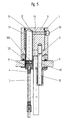
Ausführungsbeispiele der Erfindung sind in der Zeichnung dargestellt und werden im folgenden näher beschrieben. Es zeigt
- Fig. 1
- eine sanitäre Wasserauslaufarmatur in schematischer, teilweise geschnittener Darstellung mit einem geschlossenen Ablaufventil;
- Fig. 2
- die in Fig. 1 gezeigte sanitäre Wasserauslaufarmatur mit geöffnetem Ablaufventil;
- Fig. 3
- ein anderes Ausführungsbeispiel der in Fig. 1 gezeigten sanitären Wasserauslaufarmatur in schematischer Darstellung mit geöffnetem Ablaufventil;
- Fig. 4
- die in Fig. 3 gezeigte sanitäre Wasserauslaufarmatur mit einem geschlossenen Ablaufventil;
- Fig. 5
- ein weiteres Ausführungsbeispiel einer zum Teil dargestellten sanitären Wasserauslaufarmatur im Längsschnitt, wobei das Ablaufventil nicht gezeigt ist;
- Fig. 6
- ein zur Fig. 5 abgewandeltes Ausführungsbeispiel, wobei das Übertragungsglied durch einen Befestigungsbolzen der Sanitärarmatur aus dem Armaturenkörper herausgeführt ist.
Soll das Ablaufventil 20 geschlossen werden, so wird vom Benutzer der Verschlussstopfen 2 aus seiner in Fig. 2 gezeigten Position durch eine Axialbewegung in Richtung des Pfeils in Fig. 1 entgegen der Kraft der Zugfeder 4 in seine Schließstellung gedrückt. In dem Gehäuse 1 ist eine Rasteinrichtung 5 vorgesehen, mit der das Ablaufventil 20 in seiner Schließstellung gehalten wird. Hierzu ist in einer Radialbohrung 12 im Gehäuse 1 an einer Radialstange 53 ein Schnapper 51 ausgebildet. Die Radialstange 53 trägt an dem gegenüberliegenden Endbereich ein Bedienelement 50 in Form einer Drucktaste oder eines Druckknopfs. Der Schnapper 51 wird hierbei von einer Feder 52, vorzugsweise einer Tellerfeder, in seine Rastposition gedrückt. Der Schnapper 51 ist dabei mit einer Schrägfläche versehen, so dass beim Einschieben des Übertragungsglieds 3 in den Aufnahmeraum 10 der Schnapper 51 entgegen der Kraft der Feder 52 radial ausgelenkt wird und anschließend in eine als Ringnut ausgebildete Falle 54 einfasst, wie es in Fig. 1 dargestellt ist, die somit den Verschlussstopfen 2 in der Schließposition hält.
Soll dagegen das in dem Becken des Waschtisches aufgefangene Waschwasser in die Abflussleitung entleert werden, so ist vom Benutzer lediglich das an der Seitenwandung des Gehäuses 1 angeordnete Bedienelement 50 entgegen der Kraft der Feder 52 in das Gehäuse 1 einzudrücken, so dass von der Rasteinrichtung 5 das Übertragungsglied 3 freigegeben wird und die Feder 4 über das Übertragungsglied 3 den Verschlussstopfen 2 axial in dem Ablaufventil 20 in seine in Fig. 2 dargestellte Öffnungs- bzw. Ablaufposition bringt.
Ein Aufnahmeraum 10 erstreckt sich hierbei von der Unterseite des Gehäuses 1 in das Einsatzstück 11 hinein. In dem Aufnahmeraum 10 ist hierbei eine Führungshülse 31 axial festliegend angeordnet. In die Führungshülse 31 ist das als Gestänge ausgebildete Übertragungsglied 3 hineingeführt und mit einem Kopfstück 30 verbunden. In dem Kopfstück 30 ist in einer Querbohrung 300 ein von einer Feder 52 in Rastrichtung gedrückter, als Zylinderstift ausgebildeter Schnapper 51 vorgesehen.
In der in Fig. 5 gezeigten Position des Übertragungsglieds 3 befindet sich das Ablaufventil in seiner Offenstellung, wie es entsprechend des vorherigen Ausführungsbeispiels in Fig. 3 dargestellt ist. Wird nun vom Benutzer der Verschlussstopfen 2 in seine Schließstellung im Ablaufventil 20 gedrückt, so wird gleichzeitig das Übertragungsglied 3 entgegen der Kraft der Feder 4 in die Hülse 31 eingeschoben, bis der Schnapper 51 in die am Einsatzstück 11 ausgebildete Radialbohrung 12 einrastet und hierbei die Radialstange 53 mit dem Bedienelement 50 um einen geringen Teil aus dem Gehäuse 1 hinausdrängt und dadurch in dieser Stellung eine Verrastung bewerkstelligt, so dass das Ablaufventil 20 in seiner Schließstellung verharrt. Wird dagegen in der Absperrstellung des Ablaufventils vom Benutzer das Bedienelement 50 in das Gehäuse 1 entgegen der Kraft der Feder 52 gedrückt, so wird der Schnapper 51 aus seiner Rastposition in der Radialbohrung 12 verdrängt, so dass das Übertragungsglied 3 von der Feder 4 wieder in seine in Fig. 5 dargestellte Position zurückgeschoben wird, wobei das Ablaufventil 20 in seine Öffnungsposition gelangt.
Claims (10)
- Sanitäre Ventileinrichtung mit einem Gehäuse (1), vorzugsweise ein Ventilgehäuse, und einem von dessen Außenseite her betätigbaren Bedienelement (50), das über ein aus dem Gehäuse (1) herausgeführtes Übertragungsglied (3) mit einem zu betätigenden Verschlussstopfen (2) eines Ablaufventils (20) verbunden ist, dadurch gekennzeichnet, dass der Verschlussstopfen (2) entgegen der Kraft einer Feder (4) von einem Benutzer in seine Schließstellung drückbar ist, wobei im Gehäuse (1) eine Rasteinrichtung (5) zur Sicherung der Schließstellung des Verschlussstopfens (2) vorgesehen ist, die mit dem Bedienelement lösbar ist.
- Sanitäre Ventileinrichtung nach Anspruch 1, da durch gekennzeichnet, dass das Bedienelement (50) als ein in der Seitenfläche des Gehäuses (1) angeordnete Taste oder Druckknopf ausgebildet ist.
- Sanitäre Ventileinrichtung nach Anspruch 1 oder 2, dadurch gekennzeichnet, dass in einem Aufnahmeraum (10) im Gehäuse (1) als Feder (4) eine Zugfeder vorgesehen ist, die einerseits am Übertragungsglied (3) und andererseits am Gehäuse (1) befestigt ist.
- Sanitäre Ventileinrichtung nach Anspruch 1 oder 2, dadurch gekennzeichnet, dass außerhalb des Gehäuses (1), vorzugsweise unter einem Waschtisch (6), als Feder (4) eine Druckfeder vorgesehen ist, die sich einerseits an dem beweglichen Übertragungsglied (3) und andererseits am unbeweglichen Gehäuse (1) oder am Waschtisch (6) abstützt.
- Sanitäre Ventileinrichtung nach wenigstens einem der Ansprüche 1 bis 4, dadurch gekennzeichnet, dass als Rastelement (5) ein Schnapper (51) vorgesehen ist, der senkrecht zur Stellbewegung des Übertragungsglieds (3) von einer Feder (52) in seine Rastposition gedrückt ist.
- Sanitäre Ventileinrichtung nach Anspruch 5, dadurch gekennzeichnet, dass der Schnapper (51) an einer Radialstange (53) ausgebildet ist, die mit dem Bedienelement (50) verbunden ist.
- Sanitäre Ventileinrichtung nach Anspruch 5, dadurch gekennzeichnet, dass der Schnapper (51) mit der Feder (52) in einem an dem Endbereich des Übertragungsglieds (3) befestigten Kopfstück (30) in einer Querbohrung (300) angeordnet und in der Rastposition in eine Radialbohrung (12) eingreift, in der die Radialstange (53) des Bedienelements (50) angeordnet ist, derart, dass der Schnapper (51) von der Radialstange (53) durch eine Axialbewegung aus seiner Rastposition auslenkbar ist.
- Sanitäre Ventileinrichtung nach Anspruch 7, dadurch gekennzeichnet, dass das Kopfstück (30) von einer im Gehäuse (1) und/oder Einsatzstück (11) angeordneten Führungshülse (31) aufgenommen ist.
- Sanitäre Ventileinrichtung nach Anspruch 7, dadurch gekennzeichnet, dass das Kopfstück (30) von einem Führungsschlitz (111) im Gehäuse oder Einsatzstück (11) geführt ist.
- Sanitäre Ventileinrichtung nach wenigstens einem der Ansprüche 1 bis 9, dadurch gekennzeichnet, dass das Übertragungsglied (3), vorzugsweise ein Gestänge, durch einen rohrförmigen Befestigungsbolzen (13) in das Gehäuse (1) oder in ein Einsatzstück eingeführt ist.
Applications Claiming Priority (2)
| Application Number | Priority Date | Filing Date | Title |
|---|---|---|---|
| DE10012490 | 2000-03-15 | ||
| DE2000112490 DE10012490A1 (de) | 2000-03-15 | 2000-03-15 | Ventileinrichtung mit Bedienelement |
Publications (2)
| Publication Number | Publication Date |
|---|---|
| EP1134321A2 true EP1134321A2 (de) | 2001-09-19 |
| EP1134321A3 EP1134321A3 (de) | 2003-01-08 |
Family
ID=7634738
Family Applications (1)
| Application Number | Title | Priority Date | Filing Date |
|---|---|---|---|
| EP01104840A Withdrawn EP1134321A3 (de) | 2000-03-15 | 2001-02-28 | Ventileinrichtung mit Bedienelement |
Country Status (2)
| Country | Link |
|---|---|
| EP (1) | EP1134321A3 (de) |
| DE (1) | DE10012490A1 (de) |
Cited By (2)
| Publication number | Priority date | Publication date | Assignee | Title |
|---|---|---|---|---|
| EP1508646A1 (de) * | 2003-08-16 | 2005-02-23 | Hansa Metallwerke Ag | Ventileinrichtung mit Bedienelement. |
| WO2023094317A1 (de) * | 2021-11-24 | 2023-06-01 | Franke Technology And Trademark Ltd | ARMATUR, BAD- ODER KÜCHENMÖBEL MIT ARMATUR SOWIE VERFAHREN ZUM ÖFFNEN UND SCHLIEßEN EINES ABLAUFS BEI EINEM BAD- ODER KÜCHENMÖBEL |
Citations (1)
| Publication number | Priority date | Publication date | Assignee | Title |
|---|---|---|---|---|
| DE1191305B (de) | 1960-07-20 | 1965-04-15 | Grohe Armaturen Friedrich | Waschtischmischbatterie |
Family Cites Families (7)
| Publication number | Priority date | Publication date | Assignee | Title |
|---|---|---|---|---|
| US1875764A (en) * | 1928-08-10 | 1932-09-06 | Rosewood Alfred | Waste and overflow fixture for bath tubs |
| US2063399A (en) * | 1936-05-21 | 1936-12-08 | Floyd H Rasmussen | Waste and overflow for bathtubs and basins |
| GB974957A (en) * | 1962-07-05 | 1964-11-11 | Conex Sanbra Ltd | Improvements in and relating to valve plug operating means |
| GB1430234A (en) * | 1972-05-05 | 1976-03-31 | Imi Opella Ltd | Fluid control tap and plug assembly |
| DE3439468C2 (de) * | 1984-10-27 | 1994-03-03 | Grohe Armaturen Friedrich | Betätigungsvorrichtung für Wasserventile |
| DE4241023C2 (de) * | 1992-12-05 | 1996-11-14 | Heinrich Demandt | Vorrichtung zur Verhinderung oder Verminderung der durch Waschbecken, Spülbecken, Badewannen o. dgl. verursachten Keime |
| WO1996032044A1 (en) * | 1995-04-11 | 1996-10-17 | Wes Wastes Limited | Remotely operated plug |
-
2000
- 2000-03-15 DE DE2000112490 patent/DE10012490A1/de not_active Withdrawn
-
2001
- 2001-02-28 EP EP01104840A patent/EP1134321A3/de not_active Withdrawn
Patent Citations (1)
| Publication number | Priority date | Publication date | Assignee | Title |
|---|---|---|---|---|
| DE1191305B (de) | 1960-07-20 | 1965-04-15 | Grohe Armaturen Friedrich | Waschtischmischbatterie |
Cited By (2)
| Publication number | Priority date | Publication date | Assignee | Title |
|---|---|---|---|---|
| EP1508646A1 (de) * | 2003-08-16 | 2005-02-23 | Hansa Metallwerke Ag | Ventileinrichtung mit Bedienelement. |
| WO2023094317A1 (de) * | 2021-11-24 | 2023-06-01 | Franke Technology And Trademark Ltd | ARMATUR, BAD- ODER KÜCHENMÖBEL MIT ARMATUR SOWIE VERFAHREN ZUM ÖFFNEN UND SCHLIEßEN EINES ABLAUFS BEI EINEM BAD- ODER KÜCHENMÖBEL |
Also Published As
| Publication number | Publication date |
|---|---|
| EP1134321A3 (de) | 2003-01-08 |
| DE10012490A1 (de) | 2001-09-20 |
Similar Documents
| Publication | Publication Date | Title |
|---|---|---|
| EP1736695B1 (de) | Ventil, insbesondere für eine Sanitärarmatur | |
| DE102018206354B3 (de) | Misch- und Absperrventilvorrichtung sowie sanitäre Misch- und Absperrarmatur | |
| DE3401352A1 (de) | Umstellbetaetigungsglied | |
| DE3048093A1 (de) | Schalthebelmechanismus eines automatischen getriebes | |
| EP1703027B1 (de) | Vorrichtung zur Betätigung des Ablaufventils von Sanitärartikeln und insbesondere einer Badewanne | |
| DE3130703A1 (de) | Stielbefestigungsvorrichtung, insbesondere fuer haus- und gartengeraete | |
| EP2388379B1 (de) | Betätigungsvorrichtung für einen Spülkasten | |
| EP1134321A2 (de) | Ventileinrichtung mit Bedienelement | |
| DE3509649A1 (de) | Mischbatterie | |
| DE3334010A1 (de) | Drehgriffarmatur zur fernbetaetigung von zwei oder mehreren ablaufventilen in spueltischen, waschtischen o.dgl. | |
| DE3439468C2 (de) | Betätigungsvorrichtung für Wasserventile | |
| DE10051452B4 (de) | Anordnung zur Anbringung einer Brause | |
| DE19901553B4 (de) | Sanitärarmatur | |
| EP1001203B1 (de) | Drehgriff für ein Sanitärventil | |
| DE19542748A1 (de) | Umschaltventil | |
| DE3423437C2 (de) | ||
| DE10037470B4 (de) | Sanitärarmatur | |
| DE19736908C2 (de) | Einhebelmischer-Sanitärarmatur | |
| DE3151271A1 (de) | "batterieanordnung" | |
| DE3340166C2 (de) | ||
| DE8507838U1 (de) | Mischbatterie | |
| EP0524135A2 (de) | Relais | |
| EP0817932B1 (de) | Griff für sanitäre wasserarmaturen | |
| EP1083373A2 (de) | Wasserventil | |
| DE20221695U1 (de) | Hangschloss |
Legal Events
| Date | Code | Title | Description |
|---|---|---|---|
| PUAI | Public reference made under article 153(3) epc to a published international application that has entered the european phase |
Free format text: ORIGINAL CODE: 0009012 |
|
| AK | Designated contracting states |
Kind code of ref document: A2 Designated state(s): AT BE CH CY DE DK ES FI FR GB GR IE IT LI LU MC NL PT SE TR |
|
| AX | Request for extension of the european patent |
Free format text: AL;LT;LV;MK;RO;SI |
|
| PUAL | Search report despatched |
Free format text: ORIGINAL CODE: 0009013 |
|
| AK | Designated contracting states |
Kind code of ref document: A3 Designated state(s): AT BE CH CY DE DK ES FI FR GB GR IE IT LI LU MC NL PT SE TR |
|
| AX | Request for extension of the european patent |
Free format text: AL;LT;LV;MK;RO;SI |
|
| RIC1 | Information provided on ipc code assigned before grant |
Free format text: 7E 03C 1/23 A, 7F 16K 31/44 B |
|
| AKX | Designation fees paid | ||
| REG | Reference to a national code |
Ref country code: DE Ref legal event code: 8566 |
|
| STAA | Information on the status of an ep patent application or granted ep patent |
Free format text: STATUS: THE APPLICATION IS DEEMED TO BE WITHDRAWN |
|
| 18D | Application deemed to be withdrawn |
Effective date: 20030903 |