EP1134358A2 - Herstellungsmethode für den Rotor eines Turboladers - Google Patents
Herstellungsmethode für den Rotor eines Turboladers Download PDFInfo
- Publication number
- EP1134358A2 EP1134358A2 EP01105815A EP01105815A EP1134358A2 EP 1134358 A2 EP1134358 A2 EP 1134358A2 EP 01105815 A EP01105815 A EP 01105815A EP 01105815 A EP01105815 A EP 01105815A EP 1134358 A2 EP1134358 A2 EP 1134358A2
- Authority
- EP
- European Patent Office
- Prior art keywords
- rotor shaft
- machining
- turbine
- blade unit
- turbine blade
- Prior art date
- Legal status (The legal status is an assumption and is not a legal conclusion. Google has not performed a legal analysis and makes no representation as to the accuracy of the status listed.)
- Granted
Links
- 238000003754 machining Methods 0.000 title claims abstract description 75
- 238000000034 method Methods 0.000 title claims abstract description 50
- 238000003466 welding Methods 0.000 claims abstract description 43
- 238000010894 electron beam technology Methods 0.000 claims abstract description 30
- 230000008569 process Effects 0.000 description 17
- 238000005495 investment casting Methods 0.000 description 12
- 238000005259 measurement Methods 0.000 description 11
- 238000007796 conventional method Methods 0.000 description 8
- 239000012530 fluid Substances 0.000 description 6
- 238000004519 manufacturing process Methods 0.000 description 4
- 239000002184 metal Substances 0.000 description 4
- 230000009467 reduction Effects 0.000 description 4
- 230000000694 effects Effects 0.000 description 3
- 238000005452 bending Methods 0.000 description 2
- 238000005520 cutting process Methods 0.000 description 2
- 230000006872 improvement Effects 0.000 description 2
- 238000005304 joining Methods 0.000 description 2
- 238000005121 nitriding Methods 0.000 description 2
- 238000005498 polishing Methods 0.000 description 2
- 238000010791 quenching Methods 0.000 description 2
- 230000000171 quenching effect Effects 0.000 description 2
- 238000012360 testing method Methods 0.000 description 2
- 238000003070 Statistical process control Methods 0.000 description 1
- 230000002159 abnormal effect Effects 0.000 description 1
- 239000011324 bead Substances 0.000 description 1
- 238000005266 casting Methods 0.000 description 1
- 230000008602 contraction Effects 0.000 description 1
- 230000002950 deficient Effects 0.000 description 1
- 230000005484 gravity Effects 0.000 description 1
- 238000010438 heat treatment Methods 0.000 description 1
- 238000012986 modification Methods 0.000 description 1
- 230000004048 modification Effects 0.000 description 1
- 238000012545 processing Methods 0.000 description 1
- 238000003672 processing method Methods 0.000 description 1
- 239000013074 reference sample Substances 0.000 description 1
- 230000008439 repair process Effects 0.000 description 1
- 230000006641 stabilisation Effects 0.000 description 1
- 238000011105 stabilization Methods 0.000 description 1
Images


Classifications
-
- F—MECHANICAL ENGINEERING; LIGHTING; HEATING; WEAPONS; BLASTING
- F01—MACHINES OR ENGINES IN GENERAL; ENGINE PLANTS IN GENERAL; STEAM ENGINES
- F01D—NON-POSITIVE DISPLACEMENT MACHINES OR ENGINES, e.g. STEAM TURBINES
- F01D5/00—Blades; Blade-carrying members; Heating, heat-insulating, cooling or antivibration means on the blades or the members
- F01D5/02—Blade-carrying members, e.g. rotors
- F01D5/025—Fixing blade carrying members on shafts
-
- F—MECHANICAL ENGINEERING; LIGHTING; HEATING; WEAPONS; BLASTING
- F02—COMBUSTION ENGINES; HOT-GAS OR COMBUSTION-PRODUCT ENGINE PLANTS
- F02C—GAS-TURBINE PLANTS; AIR INTAKES FOR JET-PROPULSION PLANTS; CONTROLLING FUEL SUPPLY IN AIR-BREATHING JET-PROPULSION PLANTS
- F02C6/00—Plural gas-turbine plants; Combinations of gas-turbine plants with other apparatus; Adaptations of gas-turbine plants for special use
- F02C6/04—Gas-turbine plants providing heated or pressurised working fluid for other apparatus, e.g. without mechanical power output
- F02C6/10—Gas-turbine plants providing heated or pressurised working fluid for other apparatus, e.g. without mechanical power output supplying working fluid to a user, e.g. a chemical process, which returns working fluid to a turbine of the plant
- F02C6/12—Turbochargers, i.e. plants for augmenting mechanical power output of internal-combustion piston engines by increase of charge pressure
-
- F—MECHANICAL ENGINEERING; LIGHTING; HEATING; WEAPONS; BLASTING
- F05—INDEXING SCHEMES RELATING TO ENGINES OR PUMPS IN VARIOUS SUBCLASSES OF CLASSES F01-F04
- F05D—INDEXING SCHEME FOR ASPECTS RELATING TO NON-POSITIVE-DISPLACEMENT MACHINES OR ENGINES, GAS-TURBINES OR JET-PROPULSION PLANTS
- F05D2220/00—Application
- F05D2220/40—Application in turbochargers
-
- F—MECHANICAL ENGINEERING; LIGHTING; HEATING; WEAPONS; BLASTING
- F05—INDEXING SCHEMES RELATING TO ENGINES OR PUMPS IN VARIOUS SUBCLASSES OF CLASSES F01-F04
- F05D—INDEXING SCHEME FOR ASPECTS RELATING TO NON-POSITIVE-DISPLACEMENT MACHINES OR ENGINES, GAS-TURBINES OR JET-PROPULSION PLANTS
- F05D2230/00—Manufacture
- F05D2230/20—Manufacture essentially without removing material
- F05D2230/21—Manufacture essentially without removing material by casting
-
- F—MECHANICAL ENGINEERING; LIGHTING; HEATING; WEAPONS; BLASTING
- F05—INDEXING SCHEMES RELATING TO ENGINES OR PUMPS IN VARIOUS SUBCLASSES OF CLASSES F01-F04
- F05D—INDEXING SCHEME FOR ASPECTS RELATING TO NON-POSITIVE-DISPLACEMENT MACHINES OR ENGINES, GAS-TURBINES OR JET-PROPULSION PLANTS
- F05D2230/00—Manufacture
- F05D2230/20—Manufacture essentially without removing material
- F05D2230/23—Manufacture essentially without removing material by permanently joining parts together
-
- F—MECHANICAL ENGINEERING; LIGHTING; HEATING; WEAPONS; BLASTING
- F05—INDEXING SCHEMES RELATING TO ENGINES OR PUMPS IN VARIOUS SUBCLASSES OF CLASSES F01-F04
- F05D—INDEXING SCHEME FOR ASPECTS RELATING TO NON-POSITIVE-DISPLACEMENT MACHINES OR ENGINES, GAS-TURBINES OR JET-PROPULSION PLANTS
- F05D2240/00—Components
- F05D2240/60—Shafts
Definitions
- the present invention relates to a method of machining the shaft of a turbine rotor for a supercharger.
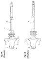
- Figs. 1A and 1B show the general configuration of a turbine rotor shaft with integrated turbine blades and rotor shaft.
- Fig. 1A shows a completed turbine rotor shaft 1
- Fig. 1B is a view showing the turbine rotor shaft 1 separated into the turbine blade unit 2 and the rotor shaft 3.
- the right hand end of the turbine rotor shaft 1 in Fig. 1A is attached to the compressor (not illustrated) with screws to form the supercharger assembly.
- Such turbine rotor shafts 1 particularly small types, rotate at speeds as high as several tens or several hundreds of thousands of revolutions per minute. Therefore it is very important that they should be accurately balanced. Consequently, imbalance of the turbine rotor shaft 1 is measured by a dynamic balancing test, and then parts A and B (2 locations), hatched in the figures, are ground to eliminate the imbalance.
- Fig. 2 is a flow chart of the processes used to machine a turbine rotor shaft according to a conventional method known in the prior art
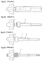
- Figs. 3A to 3D are typical views showing the corresponding steps.
- Figs. 2 and 3 first the joint portion of a precision cast turbine blade unit 2, is machined, and the rotor shaft 3 is machined to an approximate shape leaving a finishing allowance (Figs. 3A, 3B).
- Figs. 3C the joint portion of the turbine blade unit 2 and the rotor shaft 3 are joined by electron beam welding into an integrated turbine rotor shaft 1 (Fig. 3C).
- the rotor shaft is finish machined, hardened (by a nitriding process or by highfrequency quenching), and the shaft and the outer periphery of the turbine blades are ground (3D). Finally, the degree of imbalance is measured by a dynamic balancing test, part of the turbine blade unit are cut to correct the imbalance, and the turbine rotor shaft 1 is completed.
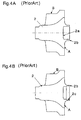
- Figs. 4A and 4B show a process for machining the joint portion of the precision cast turbine blade unit 2, before and after machining, respectively.
- the joint portion of the precision casting is bored beforehand with a boss hole 2a, and in this machining process, the end surface 2b and the inner surface 2c of the joint portion are machined using the end surface A of the joint end and the outer periphery B of the turbine blade unit as the reference surfaces.
- the center hole 2d of the turbine blade unit cannot be centered when the turbine blade unit is unattached therefore the rotor shaft 3 is first welded and finish machined, and then the center hole is machined.
- Fig. 5 is a view illustrating a process for welding the turbine blade unit 2 and the rotor shaft 3 by electron beam welding.
- the end surface 3a of the rotor shaft 3 is inserted into the inner surface 2c of the turbine blade unit 2, the entire body is held vertically using a welding jig 4, and the turbine blade unit 2 is pressed in by a ball 5.
- the joint portion is tack welded by the head 6 of the electron beam device (with a welding angle of, for example, 360°), and finally welded (with a welding angle of, for instance, 830).
- an object of the present invention is to provide a method of machining a turbine rotor shaft for superchargers, wherein the degree of imbalance that occurs unavoidably with conventional machining methods can be greatly reduced, thus the time needed to correct the imbalance and the yield of the workpieces can be increased.
- the joint portion is machined using the outer periphery of the turbine blade unit as the reference for machining.
- the turbine blade unit was precision cast, and the blade portions, used as machining references, have complicated shapes with thin walls, and because the cast portions cool quickly, they are subject to large deformations caused by shrinkage stresses.
- the dimensional accuracy of these portions is not as high as is considered necessary for use as a machining reference (about ⁇ 0.02 mm), that is, actually the accuracy is about 0.2 mm.
- the center of balance of the turbine blade unit is in the center portion which cools slowly, as the ratio of the mass to the surface area thereof is larger than that of the blades.
- this portion is less affected by shrinkage stresses, and the accuracy thereof can be maintained rather easily.
- the finished accuracy of a boss hole in the center portion of a precision casting is as high as about ⁇ 0.01 mm, as shown by the results of measurements.
- the first embodiment of the present invention is established based on the above-mentioned novel knowledge. More explicitly, according to the present invention, a cylindrical boss hole (2a) with a predetermined necessary tolerance is constructed in the joint portion of the turbine blade unit (2) which joins to the rotor shaft (3), one end of the rotor shaft previously finish machined is inserted into the boss hole, and the joint portion is welded by electron beam welding, as a novel method of machining the turbine rotor shaft of a supercharger.
- Another idea that might be proposed is to mechanically clamp the turbine blades and the rotor shaft to reduce such a deflection as described above while joining them, however, this idea cannot be applied so widely and is not desirable in terms of production efficiency because the number of factors that must be controlled, such as clamping pressure, verticality of the end surface and accuracies of the jigs increases, and also a large variety of jigs are required depending on the total length of the shaft.
- the second embodiment of the present invention takes into account the novel knowledge described above.
- a plurality of components are welded on the same axis; while the plurality of components are held in position on the same axis, the joint portions are simultaneously welded together by electron beam welding at a plurality of spots spaced at equal angles around the circumference, which is a method of producing the turbine rotor shaft for a supercharger according to the present invention.
- the aforementioned plurality of components are the turbine blade unit (2) and the rotor shaft (3), and one end (3a) of the rotor shaft is inserted into a boss hole (2a) formed in the joint portion of the turbine blade unit, and while both the turbine blade unit and the rotor shaft are held in position on the same axis, the joint portions are simultaneously welded by electron beams at a plurality of spots spaced at equal angles around the circumference.
- the joint portions are welded simultaneously at a number of locations spaced at equal angles, thus the effects of shrinkage as the molten metal solidifies are balanced as they are spaced at the same angle and bending distortions are reduced.
- the time interval and power input at each spot to be irradiated can be easily controlled by adjusting the equipment, and moreover, there are no additional factors to be controlled, so that the method is effective for increasing productivity.
- the quality of a workpiece is not affected by external factors such as the accuracy of jigs, therefore by applying the method, a high quality product can be manufactured.
- the turbine blade unit (2) and the rotor shaft (3) are welded together, and then the rear surface of the turbine blade unit is pressed against the surface plate of a machining jig, and the outer periphery of the turbine blades is clamped by a collet chuck, and the outer periphery is machined.
- the third embodiment of the present invention takes the above-mentioned novel knowledge into account.
- a method of machining a turbine rotor shaft for a supercharger is proposed, wherein the rotor shaft (3) is machined to a finished state separately, then one end of the rotor shaft is inserted into the boss hole (2a) in the turbine blade unit (2) and welded, next, using the outer periphery and the end surface of the rotor shaft as machining references, the turbine blades are machined.
- the rotor shaft (3) has been finish machined separately the accuracy of machining the rotor shaft can be improved, and the imbalance can be minimized.
- the imbalance of the turbine blades can also be kept to a minimum.
- Figs. 1A and 1B show the general configuration of a turbine rotor shaft with the turbine blade unit and the rotor shaft joined together.
- Fig. 2 is a flow chart giving the conventional processes for machining a turbine rotor shaft.
- Figs. 3A to 3D are drawings illustrating the steps in Fig. 2.
- Figs. 4A and 4B are drawings describing the processes for machining the joint portion of a precision cast turbine blade unit 2.
- Fig. 5 is an explanation drawing showing a conventional electron beam welding method.
- Fig. 6 is a flow chart of the processes used for machining a turbine rotor shaft according to the present invention.
- Figs. 7A to 7D illustrate the steps in Fig. 6.
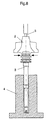
- Fig. 8 is an explanation drawing describing the electron beam welding method according to the present invention.
- Fig. 9 shows the general configuration of a turbine rotor shaft manufactured according to the method of the present invention.
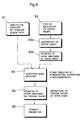
- Fig. 6 shows a flow chart of the processes used for machining a turbine rotor shaft according to the present invention
- Figs. 7A to 7D are drawings illustrating the steps in Fig. 6.
- the processing method shown in Fig. 6 according to the present invention is comprised of the steps of precision casting S1 of the turbine blade unit, finish machining S2 of the rotor shaft, hardening treatment S3a of the rotor shaft, polishing S3b of the rotor shaft, electron beam welding S4, grinding S5 of the periphery of the turbine blades and dynamic balancing S6.
- a cylindrical boss hole 2a with a predetermined tolerance is formed in the portion of the turbine blade unit 2 which is to be joined to the rotor shaft 3.
- the predetermined tolerance should be as small as possible so that one end of the rotor shaft can be inserted without any looseness and without the need for machining, for instance, about 0.01 mm.
- the center hole 2d of the turbine blade unit 2 should also be formed beforehand during the precision casting process, so as to have a similar accuracy as that of the boss hole 2a. In other respects, this precision casting process S1 is identical to the conventional method.
- the machining process S2 for the rotor shaft differs from the conventional machining steps; the intermediate processing stage is omitted, and the rotor shaft is finish machined to the final state as a separate piece as shown in Fig. 7B.
- a necessary nitriding treatment or highfrequency heat treatment and quenching is carried out, and in step S3b for polishing the rotor shaft, the surface thereof is polished.
- one end 3a of the rotor shaft 3, previously machined to the finish size at the finish machining step S2, is inserted into the boss hole 2a formed during the precision casting step S1 of the turbine blade unit, and as shown in Fig. 7C, the joint portions thereof are welded using electron beam welding.
- step S5 grinding of the outer periphery of turbine blades is carried out and, as shown in Fig. 7D, the turbine blade unit 2 is machined using as machining references the outer periphery C and the end surface E of the rotor shaft 3 which was finish machined in the finish machining step S2.
- the blades may also be machined using the center hole D of the rotor shaft 3 and the center hole 2d of the turbine blade unit as machining references.
- Fig. 8 illustrates an electron beam welding process according to the present invention.
- one end 3a of the rotor shaft 3 is inserted into the boss hole 2a formed in the portion of the turbine blade unit 2, which is to be joined to the rotor shaft 3, and while both the turbine blade unit and the rotor shaft are held in axial alignment, the joint portions thereof are electron beam welded simultaneously at a plurality of spots equally spaced circumferentially.
- the two parts are held vertically in a welding jig 4, and the end surface of the turbine blade unit 2 is held in place by a ball 5.
- the vertical engagement hole in the welding jig 4 is made slightly larger than the rotor shaft 3 that has been precision finished, so that the rotor shaft 3 can be supported very accurately in a vertical direction.
- the ball 5 is positioned accurately on the line extending through the center line of the rotor shaft 3.
- a plurality of welding heads 6 are used to electron beam weld the joint portions at a plurality of spots equally spaced around the periphery (for instance, two or three or more equally spaced spots).
- Fig. 9 shows a general configuration of the turbine rotor shaft according to the present invention.
- the turbine rotor shaft 1 joined according to the method of the present invention differs from conventional shafts in that the joint portion of the turbine blade unit 2 is not machined but the cylindrical boss hole 2a is kept as formed during precision casting, and that the beginning and ending spots of the weld beads 7 between the turbine blade unit 2 and the rotor shaft 3, made by electron beam welding, are at two or more locations.
- two or more weld beginning or ending spots are located opposite each other (symmetrical with respect to the center line) or at equally spaced angles about the center line. Therefore, these differences can be noted by observing the welded portion of the completed turbine rotor shaft 1.
- Table 1 shows the results of balance measurements carried out on five samples of the joint portion of precision cast turbine blade units 2, before and after machining.
- T-end angles and B-end angles indicate the imbalance directions (angles) on the turbine and blower ends, respectively;
- T-end divisions and B-end divisions show the out-of-balance weights at the turbine and blower ends, respectively.
- one division represents an out-of-balance weight of about 0.005g.
- the lower part of Table 1 shows that the imbalance after machining the precision casting can be as large as a maximum of 140 divisions and the mean is 78 divisions at the B end after machining, and that the out-of-balance directions, at the T and B ends, in many cases are at very different angles.
- Table 2 shows the results of balance measurements of 10 samples of the precision cast turbine blade unit 2, before machining. For these measurements, center holes were bored to prevent the workpieces from being runout during the balance measurements.
- the outer periphery of the turbine blades is used as a reference for machining the joint portions, however, the portion of the blade unit, used as a reference has a complicated shape, furthermore the wall thicknesses thereof are thin, and because it cools rapidly after casting, this portion is subject to large deformations caused by shrinkage stresses. Consequently, the accuracy (about ⁇ 0.02 mm) considered necessary for a machining reference is not achieved (in practice, it is about 0.2 mm).
- the center of the joint portion after machining using the outer periphery of the blades as a reference, is offset from the center of balance of the whole turbine blade unit, so it can be understood that the offset is a major cause of the imbalance of the completed turbine rotor shaft.
- the center of balance of the turbine blade unit is close to the center of the center portion where the ratio of the mass to the surface area is greater than that of the blades, and which cools at a slower rate.
- This portion is less affected by shrinkage stresses than the other parts, and the accuracy thereof can be maintained rather easily. It was also demonstrated from these results that the accuracy of the boss hole in the center portion of the precision casting was as high as about ⁇ 0.01 mm, according to the measurements.
- the cylindrical boss hole 2a with a predetermined necessary tolerance is formed beforehand at the joint portion of the precision cast turbine blade 2 unit, where it is to be joined to the rotor shaft 3, one end 3a of the rotor shaft 3 that has been finish machined in advance, is inserted into the boss hole 2a, and the joint portions are welded by electron beam welding, thus the imbalance that is unavoidably produced when the joint portions are machined in the conventional method is eliminated, and the rotor shaft 3 can be welded in alignment with the boss hole 2a with its center line close to the center of balance of the precision casting.
- Table 3 shows the results of measurements of runout and runout angles of 10 samples of turbine blade unit 2 and rotor shafts 3 joined together by electron beam welding according to the conventional method shown in Fig. 5. Measurements Results No. Runout Angle 1 0.060 145.0 2 0.060 127.0 3 0.030 112.0 4 0.030 112.5 5 0.060 155.0 6 0.060 206.0 7 0.065 161.5 8 0.030 234.0 9 0.120 136.0 10 0.080 143.0
- Table 3 obviously shows that rather large runouts with a mean deflection of 0.06 mm and a 3 ⁇ -value of 0.14 mm were produced by using a conventional welding methods.
- the turbine rotor shafts are subjected to deflection because of the contraction stresses produced when the molten metal solidifies after welding.
- Measurements show that, the conventional turbine rotor shaft was deflected by a mean angle of 0.14° with a 3 ⁇ -value of 0.34° . This angle corresponds to a runout with a mean value of 0.45 mm and a 3 ⁇ -value 1.09 mm at the tip for an even small turbine rotor shaft for passenger cars, and if this runout has to be removed by grinding the outer periphery of the turbine blades, the yield may obviously decrease.
- a plurality of components are welded together on the same axis; the plurality of components are placed together on the same center line, the joint portions thereof are electron beam welded simultaneously at a plurality of spots separated at equal angles around the circumference. That is, by means of a method of simultaneous welding at a number of spots separated at equal angles from each other, the condition of the joined portions during the shrinkage as the weld metal solidifies is balanced around the weld, and the deflection between the portions can be reduced.
- the time interval and a power input at each point during welding can be controlled easily by adjusting the welding equipment, and furthermore, there are no additional factors to be controlled, so the method is effective in terms of productivity.
- the quality of the workpiece is not affected by external factors such as the accuracies of the product and jigs, therefore, it can also be understood that the method can be applied effectively to manufacture a high-quality product.
- the deflection produced by the above-mentioned electron beam welding results in a runout of the workpiece to be cut, therefore the machining operation is intermittent in practice, so that the stresses caused by the machining therefor are not equally distributed and the residual stresses thereof result in a deflection after completion.
- the rotor shaft 3 is finish machined separately as a single unit, and then one end of the rotor shaft is inserted with a close fit into the boss hole 2a formed in the turbine blade unit 2 and joined thereto. Next using the outer periphery and the end surface of the rotor shaft as machining references, the turbine blades are machined.
- the accuracy of machining the rotor shaft can be increased and the imbalance can be minimized.
- the machining of the turbine rotor shaft of a supercharger has been described, in particular the joining of the turbine blade unit 2 and the rotor shaft 3, the method of the present invention can also be applied to other cases where a plurality of components are welded together coaxially such as in the fields of vacuum parts, aviation or space components, etc.
- the aforementioned present invention offers the following advantages.
- the method of the present invention for machining the turbine rotor shaft of a supercharger can greatly reduce the imbalance that a conventional machining method unavoidably accompanies. Therefore, the time needed for correcting imbalances can be reduced, the yield of the products can be improved, and other preferred advantages are also obtained.
Landscapes
- Engineering & Computer Science (AREA)
- Mechanical Engineering (AREA)
- General Engineering & Computer Science (AREA)
- Chemical & Material Sciences (AREA)
- Chemical Kinetics & Catalysis (AREA)
- General Chemical & Material Sciences (AREA)
- Combustion & Propulsion (AREA)
- Welding Or Cutting Using Electron Beams (AREA)
- Supercharger (AREA)
- Turbine Rotor Nozzle Sealing (AREA)
Applications Claiming Priority (2)
| Application Number | Priority Date | Filing Date | Title |
|---|---|---|---|
| JP2000068973A JP2001254627A (ja) | 2000-03-13 | 2000-03-13 | 過給機のタービンロータ軸の加工方法 |
| JP2000068973 | 2000-03-13 |
Publications (3)
| Publication Number | Publication Date |
|---|---|
| EP1134358A2 true EP1134358A2 (de) | 2001-09-19 |
| EP1134358A3 EP1134358A3 (de) | 2003-08-27 |
| EP1134358B1 EP1134358B1 (de) | 2006-10-18 |
Family
ID=18587943
Family Applications (1)
| Application Number | Title | Priority Date | Filing Date |
|---|---|---|---|
| EP01105815A Expired - Lifetime EP1134358B1 (de) | 2000-03-13 | 2001-03-08 | Herstellungsmethode für den Rotor eines Turboladers |
Country Status (4)
| Country | Link |
|---|---|
| US (1) | US6563074B2 (de) |
| EP (1) | EP1134358B1 (de) |
| JP (1) | JP2001254627A (de) |
| DE (1) | DE60123860T8 (de) |
Cited By (6)
| Publication number | Priority date | Publication date | Assignee | Title |
|---|---|---|---|---|
| WO2006087074A1 (de) * | 2005-02-18 | 2006-08-24 | Daimlerchrysler Ag | Verbindungeiner welle mit einem turbinenrad eines abgasturboladers |
| WO2008046556A3 (de) * | 2006-10-13 | 2008-06-19 | Borgwarner Inc | Turbolader |
| EP1956189A1 (de) * | 2007-02-12 | 2008-08-13 | Daido Castings Co., Ltd. | Turbinenrad eines Turboladers |
| GB2477564A (en) * | 2010-02-09 | 2011-08-10 | George Michael Morrell | Turbine wheels with a female tool engagement member |
| WO2018029712A3 (en) * | 2016-08-11 | 2018-07-19 | Bharat Forge Limited | Axle shaft and its manufacturing |
| CN115091145A (zh) * | 2022-07-29 | 2022-09-23 | 重庆江增船舶重工有限公司 | 一种增压器铸造涡轮加工方法 |
Families Citing this family (29)
| Publication number | Priority date | Publication date | Assignee | Title |
|---|---|---|---|---|
| JP2002235547A (ja) * | 2001-02-09 | 2002-08-23 | Shozo Shimizu | ターボチャージャ用タービン軸の接合方法 |
| JP4727532B2 (ja) * | 2006-08-18 | 2011-07-20 | 三菱重工業株式会社 | タービンロータの製造方法および排気ターボ過給機用タービンロータの製造方法 |
| US7539594B2 (en) * | 2006-09-26 | 2009-05-26 | Axiam, Incorporated | Method and apparatus for geometric rotor stacking and balancing |
| JP4748029B2 (ja) * | 2006-10-24 | 2011-08-17 | 株式会社Ihi | 過給機用タービンロータのシールブッシュ組立て、分解装置及びシールブッシュ組立て、分解方法 |
| US9044833B2 (en) * | 2008-06-19 | 2015-06-02 | Borgwarner Inc. | Rotor shaft of a turbomachine and method for the production of a rotor of a turbomachine |
| US8219353B2 (en) * | 2009-01-30 | 2012-07-10 | Axiam, Inc. | Absolute diameter measurement arm |
| US9157723B2 (en) | 2009-01-30 | 2015-10-13 | Axiam, Inc. | Absolute diameter measurement arm |
| CH700542A1 (de) * | 2009-03-03 | 2010-09-15 | Alstom Technology Ltd | Verfahren zum verbinden zweier, insbesondere rotationssymmetrischer, metallteile, mittels eines wolframinert-gas(wig)-schweissverfahrens sowie vorrichtung zur durchführung des verfahrens. |
| JP2010270645A (ja) | 2009-05-20 | 2010-12-02 | Ihi Corp | インペラの製造方法 |
| JP5439112B2 (ja) * | 2009-10-07 | 2014-03-12 | 三菱重工業株式会社 | タービン動翼 |
| JP5578839B2 (ja) * | 2009-11-30 | 2014-08-27 | 三菱重工業株式会社 | タービンロータ及びタービンロータの製造方法 |
| JP5459480B2 (ja) * | 2009-12-11 | 2014-04-02 | 株式会社Ihi | ロータ軸及び過給機 |
| CN102741522A (zh) * | 2010-02-19 | 2012-10-17 | 博格华纳公司 | 涡轮机叶轮以及用于生产其的方法 |
| JP5573295B2 (ja) * | 2010-03-30 | 2014-08-20 | トヨタ自動車株式会社 | タービンローターの製造方法 |
| JP5811613B2 (ja) * | 2011-06-15 | 2015-11-11 | 株式会社Ihi | 溶接装置及び溶接方法 |
| JP5799603B2 (ja) * | 2011-06-21 | 2015-10-28 | 株式会社Ihi | 位置決め装置 |
| CN102536431B (zh) * | 2012-01-18 | 2014-09-03 | 山东富源动力设备有限公司 | 汽油机涡轮增压器 |
| JP5912659B2 (ja) * | 2012-02-28 | 2016-04-27 | 三菱重工業株式会社 | タービンロータ |
| US20130323074A1 (en) * | 2012-05-31 | 2013-12-05 | Hamilton Sundstrand Corporation | Friction welded turbine disk and shaft |
| DE102014213132A1 (de) | 2014-01-16 | 2015-07-30 | Bosch Mahle Turbo Systems Gmbh & Co. Kg | Läufer für eine Turbine oder einen Verdichter oder eine Turbinen/Verdichter-Geometrie |
| KR101542750B1 (ko) * | 2014-07-21 | 2015-08-10 | 주식회사 우석에스티에스 | 스텐레스 소구경 관 제조방법 |
| JP6434739B2 (ja) * | 2014-08-08 | 2018-12-05 | 株式会社Ihi回転機械エンジニアリング | タービンロータ軸、及びタービンロータ軸の製造方法 |
| US10024166B2 (en) | 2014-09-16 | 2018-07-17 | Honeywell International Inc. | Turbocharger shaft and wheel assembly |
| US9827631B2 (en) | 2014-09-16 | 2017-11-28 | Honeywell International Inc. | Turbocharger shaft and wheel assembly |
| US10041351B2 (en) * | 2014-09-16 | 2018-08-07 | Honeywell International Inc. | Turbocharger shaft and wheel assembly |
| US9821410B2 (en) | 2014-09-16 | 2017-11-21 | Honeywell International Inc. | Turbocharger shaft and wheel assembly |
| CN104533624A (zh) * | 2014-12-12 | 2015-04-22 | 常州环能涡轮动力股份有限公司 | 微型涡喷发动机轴流涡轮盘轴 |
| CN108699964B (zh) | 2016-04-14 | 2020-11-17 | 株式会社Ihi | 涡轮机轴以及增压器 |
| CN105880822A (zh) * | 2016-06-07 | 2016-08-24 | 湖南天雁机械有限责任公司 | 一种利用电子束焊连接涡轮和轴的结构 |
Family Cites Families (16)
| Publication number | Priority date | Publication date | Assignee | Title |
|---|---|---|---|---|
| DE716090C (de) * | 1940-07-31 | 1942-01-13 | Rheinmetall Borsig Ag | Verfahren und Mittel zur Befestigung der Laufraeder von Kreiselmaschinen |
| US3440392A (en) * | 1964-12-02 | 1969-04-22 | Continental Can Co | Container fabrication means utilizing an electron beam |
| GB1232187A (de) * | 1970-01-03 | 1971-05-19 | ||
| FR2148901A5 (en) * | 1971-08-09 | 1973-03-23 | Alsthom | Welded rotors - with electron beam welded rotor rings |
| IT1004255B (it) * | 1973-04-19 | 1976-07-10 | August Rhyssen Hutte Ag | Procedimento e dispositivo per la produzione di parti strutturali di grandi dimensioni |
| CH563833A5 (de) * | 1974-10-28 | 1975-07-15 | Bbc Brown Boveri & Cie | |
| FR2479560A1 (fr) * | 1980-03-31 | 1981-10-02 | Sciaky Intertechnique | Machine pour le travail de metaux par faisceau d'electrons |
| JPS59218286A (ja) * | 1983-05-25 | 1984-12-08 | Aisin Seiki Co Ltd | タ−ボチヤ−ジヤ用ロ−タの溶接方法 |
| US4639194A (en) * | 1984-05-02 | 1987-01-27 | General Motors Corporation | Hybrid gas turbine rotor |
| FR2571994B1 (fr) * | 1984-10-22 | 1986-12-26 | Soudure Autogene Francaise | Machine pour le soudage interne de tubes bout a bout, par faisceau d'electrons |
| DE3816796A1 (de) * | 1988-05-17 | 1989-11-30 | Kempten Elektroschmelz Gmbh | Laufzeug mit mechanischer kupplung |
| JPH05272301A (ja) * | 1992-03-26 | 1993-10-19 | Ngk Insulators Ltd | タービンロータ及びタービンロータの加工方法 |
| DE4239710A1 (de) * | 1992-11-26 | 1994-06-01 | Abb Patent Gmbh | Läufer einer Turbine |
| DE4444082A1 (de) * | 1994-12-10 | 1996-06-13 | Abb Management Ag | Abgasturbolader für Brennkraftmaschinen |
| DE19632625A1 (de) * | 1996-08-13 | 1998-02-19 | Rofin Sinar Laser Gmbh | Verfahren und Vorrichtung zum Schweißverbinden zweier Bauteile |
| JP2002235547A (ja) * | 2001-02-09 | 2002-08-23 | Shozo Shimizu | ターボチャージャ用タービン軸の接合方法 |
-
2000
- 2000-03-13 JP JP2000068973A patent/JP2001254627A/ja active Pending
-
2001
- 2001-03-02 US US09/796,643 patent/US6563074B2/en not_active Expired - Lifetime
- 2001-03-08 DE DE60123860T patent/DE60123860T8/de active Active
- 2001-03-08 EP EP01105815A patent/EP1134358B1/de not_active Expired - Lifetime
Cited By (7)
| Publication number | Priority date | Publication date | Assignee | Title |
|---|---|---|---|---|
| WO2006087074A1 (de) * | 2005-02-18 | 2006-08-24 | Daimlerchrysler Ag | Verbindungeiner welle mit einem turbinenrad eines abgasturboladers |
| WO2008046556A3 (de) * | 2006-10-13 | 2008-06-19 | Borgwarner Inc | Turbolader |
| US8241006B2 (en) | 2006-10-13 | 2012-08-14 | Borgwarner Inc. | Turbocharger |
| EP1956189A1 (de) * | 2007-02-12 | 2008-08-13 | Daido Castings Co., Ltd. | Turbinenrad eines Turboladers |
| GB2477564A (en) * | 2010-02-09 | 2011-08-10 | George Michael Morrell | Turbine wheels with a female tool engagement member |
| WO2018029712A3 (en) * | 2016-08-11 | 2018-07-19 | Bharat Forge Limited | Axle shaft and its manufacturing |
| CN115091145A (zh) * | 2022-07-29 | 2022-09-23 | 重庆江增船舶重工有限公司 | 一种增压器铸造涡轮加工方法 |
Also Published As
| Publication number | Publication date |
|---|---|
| DE60123860T8 (de) | 2007-09-13 |
| DE60123860T2 (de) | 2007-03-15 |
| EP1134358B1 (de) | 2006-10-18 |
| DE60123860D1 (de) | 2006-11-30 |
| US20010027963A1 (en) | 2001-10-11 |
| EP1134358A3 (de) | 2003-08-27 |
| US6563074B2 (en) | 2003-05-13 |
| JP2001254627A (ja) | 2001-09-21 |
Similar Documents
| Publication | Publication Date | Title |
|---|---|---|
| US6563074B2 (en) | Method of machining the turbine rotor shaft of a supercharger | |
| US8516676B2 (en) | Method of manufacture of aerofoil assemblies having datum features located in complementary fixtures | |
| CN110977338B (zh) | 一种拼焊结构进气机匣的集成方法 | |
| JP6917904B2 (ja) | 円筒区分と異形区分とを備えた軸状の工作物を研削完全加工する方法 | |
| CN115401421B (zh) | 一种多联涡轮导向叶片的制备方法 | |
| CN105750834B (zh) | 一种滚动轴承钢与镍基高温合金组成的轴颈的加工方法 | |
| CN111524681A (zh) | 一种永磁体的充磁方法及高速转子的制造方法 | |
| US9114480B2 (en) | Methods for joining a monocrystalline part to a polycrystalline part by means of an adapter piece made of polycrystalline material | |
| CN107932215A (zh) | 一种薄壁细长轴类零件顶尖孔的加工方法及其使用的夹具 | |
| JP3916146B2 (ja) | 過給機のタービン翼の加工方法 | |
| US6892930B2 (en) | Process for reconditioning worn or out-of-spec components | |
| EP3117946B1 (de) | Verfahren zum linearen reibschweissen | |
| CN118848600B (zh) | 一种机匣内套装夹工装及机匣内套导流环去除方法 | |
| CN120002032A (zh) | 一种零件调转180°高精度同轴孔镗削方法 | |
| CN107234475A (zh) | 机械加工精密硬车削轴承外圈专用夹具 | |
| CN113878299B (zh) | 一种轴承座衬套的返修加工方法 | |
| CN115647854B (zh) | 一种轴承支座衬套孔的加工方法 | |
| CN116833684A (zh) | 一种精密滑枕的制备工艺以及工装 | |
| CN114289749A (zh) | 加工偏心外圆车用夹具及夹持方法 | |
| CN113543930A (zh) | 涡旋件加工装置和加工方法 | |
| TWI912084B (zh) | 軸類工件複雜加工面的修護校正方法 | |
| CN117680929B (zh) | 一种有质量质心控制要求的压力容器制造方法 | |
| CN114378760B (zh) | 用于在空心轴中安装塞子的设备 | |
| CN112276496B (zh) | 一种低压涡轮盘的机加过程变形解决方法 | |
| CN223811935U (zh) | 一种脆硬工件自动化研磨设备 |
Legal Events
| Date | Code | Title | Description |
|---|---|---|---|
| PUAI | Public reference made under article 153(3) epc to a published international application that has entered the european phase |
Free format text: ORIGINAL CODE: 0009012 |
|
| AK | Designated contracting states |
Kind code of ref document: A2 Designated state(s): AT BE CH CY DE DK ES FI FR GB GR IE IT LI LU MC NL PT SE TR |
|
| AX | Request for extension of the european patent |
Free format text: AL;LT;LV;MK;RO;SI |
|
| 17P | Request for examination filed |
Effective date: 20011016 |
|
| PUAL | Search report despatched |
Free format text: ORIGINAL CODE: 0009013 |
|
| AK | Designated contracting states |
Designated state(s): AT BE CH CY DE DK ES FI FR GB GR IE IT LI LU MC NL PT SE TR |
|
| AX | Request for extension of the european patent |
Extension state: AL LT LV MK RO SI |
|
| RIC1 | Information provided on ipc code assigned before grant |
Ipc: 7F 01D 5/02 A Ipc: 7B 23K 15/00 B Ipc: 7F 02C 6/12 B |
|
| 17Q | First examination report despatched |
Effective date: 20031126 |
|
| AKX | Designation fees paid |
Designated state(s): DE FR GB IT NL |
|
| GRAP | Despatch of communication of intention to grant a patent |
Free format text: ORIGINAL CODE: EPIDOSNIGR1 |
|
| GRAS | Grant fee paid |
Free format text: ORIGINAL CODE: EPIDOSNIGR3 |
|
| GRAA | (expected) grant |
Free format text: ORIGINAL CODE: 0009210 |
|
| AK | Designated contracting states |
Kind code of ref document: B1 Designated state(s): DE FR GB IT NL |
|
| PG25 | Lapsed in a contracting state [announced via postgrant information from national office to epo] |
Ref country code: IT Free format text: LAPSE BECAUSE OF FAILURE TO SUBMIT A TRANSLATION OF THE DESCRIPTION OR TO PAY THE FEE WITHIN THE PRESCRIBED TIME-LIMIT;WARNING: LAPSES OF ITALIAN PATENTS WITH EFFECTIVE DATE BEFORE 2007 MAY HAVE OCCURRED AT ANY TIME BEFORE 2007. THE CORRECT EFFECTIVE DATE MAY BE DIFFERENT FROM THE ONE RECORDED. Effective date: 20061018 |
|
| REG | Reference to a national code |
Ref country code: GB Ref legal event code: FG4D |
|
| REF | Corresponds to: |
Ref document number: 60123860 Country of ref document: DE Date of ref document: 20061130 Kind code of ref document: P |
|
| ET | Fr: translation filed | ||
| PLBE | No opposition filed within time limit |
Free format text: ORIGINAL CODE: 0009261 |
|
| STAA | Information on the status of an ep patent application or granted ep patent |
Free format text: STATUS: NO OPPOSITION FILED WITHIN TIME LIMIT |
|
| 26N | No opposition filed |
Effective date: 20070719 |
|
| REG | Reference to a national code |
Ref country code: FR Ref legal event code: PLFP Year of fee payment: 16 |
|
| REG | Reference to a national code |
Ref country code: FR Ref legal event code: PLFP Year of fee payment: 17 |
|
| REG | Reference to a national code |
Ref country code: FR Ref legal event code: PLFP Year of fee payment: 18 |
|
| PGFP | Annual fee paid to national office [announced via postgrant information from national office to epo] |
Ref country code: NL Payment date: 20180319 Year of fee payment: 18 Ref country code: GB Payment date: 20180319 Year of fee payment: 18 |
|
| PGFP | Annual fee paid to national office [announced via postgrant information from national office to epo] |
Ref country code: FR Payment date: 20180319 Year of fee payment: 18 |
|
| PGFP | Annual fee paid to national office [announced via postgrant information from national office to epo] |
Ref country code: DE Payment date: 20180328 Year of fee payment: 18 |
|
| PGFP | Annual fee paid to national office [announced via postgrant information from national office to epo] |
Ref country code: IT Payment date: 20180330 Year of fee payment: 18 |
|
| REG | Reference to a national code |
Ref country code: DE Ref legal event code: R119 Ref document number: 60123860 Country of ref document: DE |
|
| REG | Reference to a national code |
Ref country code: NL Ref legal event code: MM Effective date: 20190401 |
|
| GBPC | Gb: european patent ceased through non-payment of renewal fee |
Effective date: 20190308 |
|
| PG25 | Lapsed in a contracting state [announced via postgrant information from national office to epo] |
Ref country code: GB Free format text: LAPSE BECAUSE OF NON-PAYMENT OF DUE FEES Effective date: 20190308 Ref country code: DE Free format text: LAPSE BECAUSE OF NON-PAYMENT OF DUE FEES Effective date: 20191001 Ref country code: NL Free format text: LAPSE BECAUSE OF NON-PAYMENT OF DUE FEES Effective date: 20190401 |
|
| PG25 | Lapsed in a contracting state [announced via postgrant information from national office to epo] |
Ref country code: FR Free format text: LAPSE BECAUSE OF NON-PAYMENT OF DUE FEES Effective date: 20190331 Ref country code: IT Free format text: LAPSE BECAUSE OF NON-PAYMENT OF DUE FEES Effective date: 20190308 |