EP1134360A2 - Verstellvorrichtung für den Durchmesser des Stators eines Gasturbinenwerks - Google Patents
Verstellvorrichtung für den Durchmesser des Stators eines Gasturbinenwerks Download PDFInfo
- Publication number
- EP1134360A2 EP1134360A2 EP01400059A EP01400059A EP1134360A2 EP 1134360 A2 EP1134360 A2 EP 1134360A2 EP 01400059 A EP01400059 A EP 01400059A EP 01400059 A EP01400059 A EP 01400059A EP 1134360 A2 EP1134360 A2 EP 1134360A2
- Authority
- EP
- European Patent Office
- Prior art keywords
- hook
- spacer
- arrangement according
- housing
- casing
- Prior art date
- Legal status (The legal status is an assumption and is not a legal conclusion. Google has not performed a legal analysis and makes no representation as to the accuracy of the status listed.)
- Granted
Links
- 125000006850 spacer group Chemical group 0.000 claims abstract description 47
- 238000004891 communication Methods 0.000 claims abstract description 12
- 238000005192 partition Methods 0.000 claims description 24
- 238000007789 sealing Methods 0.000 claims description 4
- 210000003462 vein Anatomy 0.000 claims description 4
- 238000007664 blowing Methods 0.000 claims description 2
- 238000009423 ventilation Methods 0.000 abstract description 30
- 239000007789 gas Substances 0.000 description 38
- 238000011144 upstream manufacturing Methods 0.000 description 5
- 230000008901 benefit Effects 0.000 description 3
- 230000000694 effects Effects 0.000 description 3
- 239000012634 fragment Substances 0.000 description 2
- 230000003313 weakening effect Effects 0.000 description 2
- 238000012550 audit Methods 0.000 description 1
- 239000000969 carrier Substances 0.000 description 1
- 239000006185 dispersion Substances 0.000 description 1
- 238000005553 drilling Methods 0.000 description 1
- 230000002349 favourable effect Effects 0.000 description 1
- 238000004519 manufacturing process Methods 0.000 description 1
- 239000000463 material Substances 0.000 description 1
- 238000013021 overheating Methods 0.000 description 1
- 230000000750 progressive effect Effects 0.000 description 1
- 230000001105 regulatory effect Effects 0.000 description 1
- 238000005070 sampling Methods 0.000 description 1
- 230000001502 supplementing effect Effects 0.000 description 1
- 238000005303 weighing Methods 0.000 description 1
Images


Classifications
-
- F—MECHANICAL ENGINEERING; LIGHTING; HEATING; WEAPONS; BLASTING
- F01—MACHINES OR ENGINES IN GENERAL; ENGINE PLANTS IN GENERAL; STEAM ENGINES
- F01D—NON-POSITIVE DISPLACEMENT MACHINES OR ENGINES, e.g. STEAM TURBINES
- F01D11/00—Preventing or minimising internal leakage of working-fluid, e.g. between stages
- F01D11/08—Preventing or minimising internal leakage of working-fluid, e.g. between stages for sealing space between rotor blade tips and stator
- F01D11/14—Adjusting or regulating tip-clearance, i.e. distance between rotor-blade tips and stator casing
- F01D11/20—Actively adjusting tip-clearance
- F01D11/24—Actively adjusting tip-clearance by selectively cooling-heating stator or rotor components
-
- F—MECHANICAL ENGINEERING; LIGHTING; HEATING; WEAPONS; BLASTING
- F01—MACHINES OR ENGINES IN GENERAL; ENGINE PLANTS IN GENERAL; STEAM ENGINES
- F01D—NON-POSITIVE DISPLACEMENT MACHINES OR ENGINES, e.g. STEAM TURBINES
- F01D25/00—Component parts, details, or accessories, not provided for in, or of interest apart from, other groups
- F01D25/24—Casings; Casing parts, e.g. diaphragms, casing fastenings
- F01D25/246—Fastening of diaphragms or stator-rings
-
- F—MECHANICAL ENGINEERING; LIGHTING; HEATING; WEAPONS; BLASTING
- F05—INDEXING SCHEMES RELATING TO ENGINES OR PUMPS IN VARIOUS SUBCLASSES OF CLASSES F01-F04
- F05D—INDEXING SCHEME FOR ASPECTS RELATING TO NON-POSITIVE-DISPLACEMENT MACHINES OR ENGINES, GAS-TURBINES OR JET-PROPULSION PLANTS
- F05D2240/00—Components
- F05D2240/10—Stators
- F05D2240/11—Shroud seal segments
Definitions
- the field of this invention is a diameter adjustment arrangement of a stator gas turbine.
- Some gas turbines include our days of the internal diameter adjustment devices of the stator in order to bring back the play existing between the stator and rotor blade tips at a value as low as possible; a current layout to ensure this diameter adjustment is to take a portion of the cooler gases from compressors and route it through the stator to that it is blown on piloting rings of the stator which extend in front of the rotor blades.
- a stator ventilation whose diameter is modified according to the temperature and flow of ventilation gases.
- the gas sampling is twofold: a so-called hot spring with fixed flow allows the expansion of the casing when necessary, another so-called cold source with variable and controlled flow makes it possible to contract the casing.
- the path of ventilation gases from the hot spring borrows an internal volume from the stator, between the rings to be ventilated and a casing which surrounded.
- Spacers connecting the rings to the housing include in particular transverse partitions which separate the volume of the journey into rooms and through which it is therefore necessary to spare communications to allow the flow of gases from ventilation.
- Many examples of how these communications have been proposed in the prior art, but we observe that good ventilation is not easy to insure because it must be well distributed not only between successive rings, but on the surface of each of the rings, otherwise we observe undulations of the rings produced by the differences in ventilation and expansion intensity thermal around their circumferences, and therefore regions where gas leaks at the tip of the rotor blades will remain.
- the openings in through the spacers have the effect of weaken, with dangerous consequences for portions of the machine subjected to strong mechanical stresses, since concentrations constraints generally appear around these openings.
- the object of the invention is therefore to propose a gas turbine stator arrangement, of which the interior is compartmentalized but provided with openings allowing ventilation gas to be blown out stator rings subject to adjustment, where the openings are designed to produce great regularity of ventilation around the rings without unduly weaken the structural elements to through which they are pierced.
- the invention thus relates, in its form the most general, a diameter adjustment arrangement a gas turbine stator, the stator comprising a casing, rings bordering a flow vein of gas and located in front of respective stages of blades moving parts of a rotor, the rings being surrounded by the housing and hooked to the housing by spacers circular, each including a partition transverse extending from the casing to one of the rings and separating two rooms, the partition comprising an edge curved outer hook and spacer hook between a main portion of the housing and an appendage respective curved crank hook associated with said audit spacer hook, pass communications of a pressurized gas flow existing between the rooms, characterized in that at least one of the communications is carried out by means of recesses operated through a hook junction composed of a spacer hook and the housing hook which is associated.
- the communication between rooms that offers here includes longitudinal notches dug through each of the spacer hooks, a circular gap located under the housing hook respective and outside the spacer hook, and radial notches operated on the hook spacer between the longitudinal notches and opening onto one of said chambers.
- radial notches extend to a depth sufficient to protrude from the housing hook, i.e. they include collecting portions followed by holes; this last arrangement lends itself willing to calibrate the ventilation flow (according to the entry section of the radial notches or drilling) and a tranquilization of the gas in the chamber downstream of the flow (after passing through the tightened part of the holes).
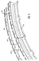
- Figure 1 illustrates a fragment of a gas turbine stator 1 found with surrounding elements in figure 2.
- the stator 1 includes a casing 2 on the outside, and which surrounds rings 3 coming opposite stages of movable blades 5 of a rotor 6 within a flow stream 7 of the gas, and the rings 3 alternate with other rings 8 carriers of fixed blades 9 along the vein 7.
- the gas turbines include multiple rings 3 and 8 successive, but only one of each species is illustrated in the fragment of FIGS. 1 and 2, the invention not being here applied only to a ring 3.
- Spacers 10 join the rings 3 to housing 1. Junctions generally composed of the assembly of a pair of hooks and that will be described in detail join the spacer 10 to the stator 1 to front and rear, and spacer 10 to ring 3 front and rear; they carry respectively references 11, 12, 13 and 14. We are trying to reduce the clearance between the ring 3 and the movable blades 5 during the operation of the gas turbine. More gas costs originating from a compressor upstream of the gas turbine are drawn off to be blown to the outside of ring 3, on the face opposite to movable blades 5.
- the spacer 10 includes a transverse bulkhead at front 15, between junctions 11 and 13, a transverse partition at the rear 16, between junctions 12 and 14, and a partition intermediate transverse 17 connecting the two previous and arranged obliquely and substantially between junctions 13 and 12, the ventilation gases passing within the casing 2 but around the rings 3 and 8 first pass through a first chamber 18 to the front of the bulkhead before 15, then by a chamber intermediate 19 between the front bulkhead 15 and the intermediate partition 17, and finally by a downstream chamber 20 between the intermediate partition 17 and the ring 3.
- This downstream chamber 20 is further delimited by the rear bulkhead 16, and it is divided by a cover provided with holes, or more generally a box 21 composed of several of these covers, already proposed in art to help equalize the ventilation (for example in the US patent 5,273,396).
- the rear partition 16 is a partition external ventilation chambers 18, 19 and 20, since the ventilation flow stops there and that another atmosphere extends beyond.
- Communications to make pass the compressor gases through chambers 18, 19 then 20, according to the invention include openings mainly through the junctions 11 and 12 to casing 2. The part of description below will benefit from being read also referring to Figure 3.
- Junction 11 is composed of an edge of the front bulkhead 15, curved downstream (or rear) to form a spacer hook 26, and a associated appendix of casing 2, the end of which is curved upstream (or forward) to give a housing hook 27.
- the partitions rear and intermediate 16 and 17 end on an edge backward common, forming another hook spacer 28, while an associated appendage of the casing 2 is also bent forward for give another crank hook 29.
- the hooks spacer 26 and 28 are inserted between the casing 2 to the outside and, respectively, the housing hooks 27 and 29 inside.
- the spacer hook 26 located at the front is not a continuous or intact structure, but it is hollowed out with longitudinal notches 30 regularly distributed around its circumference and parallel between them, which cut it right through on its face exterior and therefore extend from the upstream chamber 18 to the annular interval 31 between the end of the spacer hook 26 and the bottom of the housing hook 27; the spacer hook 26 is also notched radial notches 32, also parallel between them and evenly distributed around the circumference of the spacer hook 26, halfway between the notches longitudinal 30, and these radial notches 32 have a sufficient depth to protrude from the end of the hook casing 27: the intervals 31 and 34 formed between the ends of the spacer hooks 26 and 28 and the bottom of the housing hooks 27 and 29 are worth seeing their meridian sections increased by practicing rebates 50 (illustrated in FIG.
- the advantages of 50 rebates are multiple: reduction of the surface contact between spacer and housing and therefore overheating the casing by conduction; best mastery of the circulating air passage section circumferential because the manufacturing dispersions are lower for 50 rebates than for bottom of the housing hooks; and so better control of circumferential speed of air flow and exchange coefficients convective; larger convective exchange surface over the casing 1 and therefore better control of the flow of heat and its homogeneity.
- Heat exchanges are produced in intervals 31 and 34. They are regulated by: the surface wetted by gas from casing 1; speed air flow in the circumferential direction; the number of longitudinal cuts 30 and 33, and therefore the length of the circumferential paths.
- the notches 30 and 32 generating stress and weakening concentrations of the structure, are only established on the hooks of the junction 11, i.e. edge portions, little likely to give high concentrations of constraints.
- the dispersal movement of the flow by the interval 31 helps to standardize the flow of gas on the circumference of the machine, and therefore the effect ventilation; changes of direction to which the flow is subjected produce losses of charge welcome for the efficiency of the ventilation ; finally, the gases come out in the direction centripetal, towards the ring 3.
- a similar arrangement makes it possible to make connect rooms 19 and 20.
- the hook spacer 28 located at the back is first dug longitudinal notches 33, similar to those 30 of the hook 26, and an interval 34 similar to the interval 31 exists between the end of the spacer hook 28 and the bottom of the housing hook 29; gases from ventilation disperse in this interval 34 towards radial notches 35 operated between the notches longitudinal 33.
- gases from ventilation disperse in this interval 34 towards radial notches 35 operated between the notches longitudinal 33.
- They do not communicate directly to the downstream chamber 20 but in holes 36, in variable number by radial notch 35.
- the holes 36 extend to the chamber 20 in crossing the material of the spacer 10 at the junction partitions 16 and 17. This arrangement offers the same characteristics and advantages of assembly previous 11, and holes 36 are directed obliquely with a strong centripetal component which directs the ventilation gas towards ring 3.
- notches 33 can still open on rebates 50 which extend them towards the interval 34.
- the existence of intervals 31 and 34 is guaranteed by the stop established by the end of the hook casing 29 located behind against the rear bulkhead 16, and the ring 8 located immediately upstream maintains this support by weighing on the front bulkhead 15 to the location of the outer front junction 13. Sealing downstream of junction 12 is guaranteed by a seal 37 housed in a groove of the hook 29 and compressed between it and the rear partition 16; it's about a joint whose section is composed of three lobes in extension and therefore called omega joint.
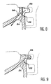
- Figures 8 and 9 are thus possible to obtain the same result: in Figure 8, the radial notches 53 (instead of 35) extend in counterbore on a portion 54 of the rear partition 16 for clear access to the holes 36 while reducing the width of the planar support 52, but without interrupting it; at Figure 9, the notches 55 (instead of 35 or 53) do not extend only in the internal face of the hook spacer 28, in front of the housing hook 29, thus lengthening the path of the gases in the cavities 34. Other arrangements are also possible.
- the part 54 recessed from the rear partition 16 facilitates the entry of the air in the holes.
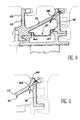
- the box 21 can be a simple sheet impact and multi-perforated. It can be fixed either on the ring, or on the spacer. Box 21 is attached to edges 38 and 39 of the ring 3, of usual in the art, in Figure 1; The direction favorable ventilation gases would bring the box 21 closer to the gas inlet in the chamber 20, by supporting it with flanges 40 and 41 of the spacer 10 which would be located on the partitions 15 and 16, as shown in Figure 4.
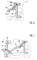
- the holes 36 shown were of constant section. They could be replaced by divergent holes with increasing section towards the downstream chamber 20, such as the stepped bore 42, or with an abrupt variation in diameter, of FIG. 5 and the horn 43, or with progressive variation of diameter, of Figure 6; these holes 42 and 43 would be located like hole 36, but the proportions that it would be possible to give to inlet and outlet diameters would act to faith on gas flow calibration of ventilation allowed (thanks to the smaller diameter entrance) and on the tranquilization effect obtained at the entrance to chamber 20 (thanks to the larger diameter at the exit), which is accompanied by better feeding the box 21.
- the invention can also be combined with more classic communications between rooms, such as holes 44 in FIG. 7 operated from the chamber 18 to chamber 20 through the matter of the spacer 10 disposed at the junction of the partitions transverse 15 and 17; the invention would then have consequence of attenuating the weakening effect mechanics produced by holes 44, reducing their required number.
- stator can be provided with external ribs 45 in front or between which the chambers of distribution 46 of another ventilation gas network forming a cold source, these distribution chambers 46 being connected to supply pipes 47 used for gas circulation.
- the rooms of distribution 46 are pierced with blowing orifices in front of the ribs 45 so that the gas reaches them.
- the second gas flow from ventilation will be drawn from a portion of the compressor located further upstream than the racking portion of the first flow, so the gas in this second flow will be cooler. Adjusting the diameter of the ring 3 will then consist of a combined adjustment of the two flow rates ventilation, which will give precision excellent.
Landscapes
- Engineering & Computer Science (AREA)
- Mechanical Engineering (AREA)
- General Engineering & Computer Science (AREA)
- Structures Of Non-Positive Displacement Pumps (AREA)
- Turbine Rotor Nozzle Sealing (AREA)
- Control Of Turbines (AREA)
Applications Claiming Priority (2)
| Application Number | Priority Date | Filing Date | Title |
|---|---|---|---|
| FR0000371 | 2000-01-13 | ||
| FR0000371A FR2803871B1 (fr) | 2000-01-13 | 2000-01-13 | Agencement de reglage de diametre d'un stator de turbine a gaz |
Publications (3)
| Publication Number | Publication Date |
|---|---|
| EP1134360A2 true EP1134360A2 (de) | 2001-09-19 |
| EP1134360A3 EP1134360A3 (de) | 2002-07-31 |
| EP1134360B1 EP1134360B1 (de) | 2005-11-16 |
Family
ID=8845853
Family Applications (1)
| Application Number | Title | Priority Date | Filing Date |
|---|---|---|---|
| EP01400059A Expired - Lifetime EP1134360B1 (de) | 2000-01-13 | 2001-01-11 | Verstellvorrichtung für den Durchmesser des Stators eines Gasturbinenwerks |
Country Status (10)
| Country | Link |
|---|---|
| US (1) | US6666645B1 (de) |
| EP (1) | EP1134360B1 (de) |
| JP (1) | JP4248785B2 (de) |
| CA (1) | CA2366363C (de) |
| DE (1) | DE60114910T2 (de) |
| ES (1) | ES2248248T3 (de) |
| FR (1) | FR2803871B1 (de) |
| RU (1) | RU2292466C2 (de) |
| UA (1) | UA70353C2 (de) |
| WO (1) | WO2001051771A2 (de) |
Cited By (3)
| Publication number | Priority date | Publication date | Assignee | Title |
|---|---|---|---|---|
| EP3092373A4 (de) * | 2013-12-17 | 2017-09-27 | United Technologies Corporation | Messplatte für eine aussenluftdichtung für eine turbinenschaufel |
| CN109154208A (zh) * | 2016-03-21 | 2019-01-04 | 赛峰航空陶瓷技术公司 | 不具有冷装配间隙的涡轮环组件 |
| EP4345255A1 (de) * | 2022-09-30 | 2024-04-03 | RTX Corporation | Äussere laufschaufelluftdichtung mit haltering |
Families Citing this family (49)
| Publication number | Priority date | Publication date | Assignee | Title |
|---|---|---|---|---|
| FR2816352B1 (fr) * | 2000-11-09 | 2003-01-31 | Snecma Moteurs | Ensemble de ventilation d'un anneau de stator |
| US6893217B2 (en) * | 2002-12-20 | 2005-05-17 | General Electric Company | Methods and apparatus for assembling gas turbine nozzles |
| US6892931B2 (en) * | 2002-12-27 | 2005-05-17 | General Electric Company | Methods for replacing portions of turbine shroud supports |
| FR2857406B1 (fr) * | 2003-07-10 | 2005-09-30 | Snecma Moteurs | Refroidissement des anneaux de turbine |
| DE102005013796A1 (de) * | 2005-03-24 | 2006-09-28 | Alstom Technology Ltd. | Wärmestausegment |
| DE102005013797A1 (de) * | 2005-03-24 | 2006-09-28 | Alstom Technology Ltd. | Wärmestausegment |
| US7600967B2 (en) * | 2005-07-30 | 2009-10-13 | United Technologies Corporation | Stator assembly, module and method for forming a rotary machine |
| FR2899281B1 (fr) * | 2006-03-30 | 2012-08-10 | Snecma | Dispositif de refroidissement d'un carter de turbine d'une turbomachine |
| US20070249823A1 (en) * | 2006-04-20 | 2007-10-25 | Chemagis Ltd. | Process for preparing gemcitabine and associated intermediates |
| US7785063B2 (en) * | 2006-12-15 | 2010-08-31 | Siemens Energy, Inc. | Tip clearance control |
| US7597533B1 (en) | 2007-01-26 | 2009-10-06 | Florida Turbine Technologies, Inc. | BOAS with multi-metering diffusion cooling |
| US7665962B1 (en) | 2007-01-26 | 2010-02-23 | Florida Turbine Technologies, Inc. | Segmented ring for an industrial gas turbine |
| MY161317A (en) * | 2008-02-20 | 2017-04-14 | General Electric Technology Gmbh | Gas turbine |
| US8123473B2 (en) * | 2008-10-31 | 2012-02-28 | General Electric Company | Shroud hanger with diffused cooling passage |
| JP5254774B2 (ja) * | 2008-12-22 | 2013-08-07 | 三菱重工業株式会社 | 熱機関の流体シール構造 |
| EP2415969A1 (de) | 2010-08-05 | 2012-02-08 | Siemens Aktiengesellschaft | Bauteil einer Turbine mit Lamellendichtungen und Verfahren zur Abdichtung gegen Leckagen zwischen einer Schaufel und einem Trägerelement |
| RU2465466C1 (ru) * | 2011-05-05 | 2012-10-27 | Открытое акционерное общество "Авиадвигатель" | Высокотемпературная турбина газотурбинного двигателя |
| US8826668B2 (en) * | 2011-08-02 | 2014-09-09 | Siemens Energy, Inc. | Two stage serial impingement cooling for isogrid structures |
| US9080458B2 (en) | 2011-08-23 | 2015-07-14 | United Technologies Corporation | Blade outer air seal with multi impingement plate assembly |
| CN104508251B (zh) | 2012-04-27 | 2016-08-24 | 通用电气公司 | 用于燃气涡轮发动机的护罩组件和密封件 |
| ES2531468T3 (es) * | 2012-10-12 | 2015-03-16 | Mtu Aero Engines Gmbh | Estructura de caja con obturación y refrigeración mejoradas |
| EP2728255A1 (de) * | 2012-10-31 | 2014-05-07 | Alstom Technology Ltd | Heißgas-Segmentanordnung |
| US9752451B2 (en) * | 2012-12-19 | 2017-09-05 | United Technologies Corporation | Active clearance control system with zone controls |
| FR3002972B1 (fr) * | 2013-03-06 | 2015-04-17 | Snecma | Dispositif de ventilation d'un carter de stator d'une turbomachine comprenant un ajustement en direction axiale |
| FR3002971B1 (fr) * | 2013-03-06 | 2015-04-17 | Snecma | Dispositif de ventilation d'un carter de stator d'une turbomachine, comprenant un ajustement sur des circonferences |
| DE102013212501A1 (de) * | 2013-06-27 | 2014-12-31 | MTU Aero Engines AG | Leitschaufelsegment mit stirnseitiger Ausnehmung |
| US9464538B2 (en) * | 2013-07-08 | 2016-10-11 | General Electric Company | Shroud block segment for a gas turbine |
| FR3009579B1 (fr) * | 2013-08-07 | 2015-09-25 | Snecma | Carter de turbine en deux materiaux |
| EP3044427B8 (de) * | 2013-09-12 | 2021-04-07 | Raytheon Technologies Corporation | Gasturbinentriebwerk und zugehöriges verfahren zur regelung des schaufelspitzenspiels |
| EP3183431B1 (de) | 2014-08-22 | 2018-10-10 | Siemens Aktiengesellschaft | Deckbandkühlsystem für deckbänder neben in schaufeln in gasturbinenmotoren |
| EP3034803A1 (de) * | 2014-12-16 | 2016-06-22 | Rolls-Royce Corporation | Hängersystem für eine turbinenmotorkomponente |
| US20170248030A1 (en) * | 2016-02-26 | 2017-08-31 | General Electric Company | Encapsulated Cooling for Turbine Shrouds |
| US10815814B2 (en) * | 2017-05-08 | 2020-10-27 | Raytheon Technologies Corporation | Re-use and modulated cooling from tip clearance control system for gas turbine engine |
| GB201708744D0 (en) * | 2017-06-01 | 2017-07-19 | Rolls Royce Plc | Clearance control arrangement |
| US10677084B2 (en) | 2017-06-16 | 2020-06-09 | Honeywell International Inc. | Turbine tip shroud assembly with plural shroud segments having inter-segment seal arrangement |
| US10900378B2 (en) | 2017-06-16 | 2021-01-26 | Honeywell International Inc. | Turbine tip shroud assembly with plural shroud segments having internal cooling passages |
| US20190218928A1 (en) * | 2018-01-17 | 2019-07-18 | United Technologies Corporation | Blade outer air seal for gas turbine engine |
| FR3082872B1 (fr) * | 2018-06-25 | 2021-06-04 | Safran Aircraft Engines | Dispositif de refroidissement d'un carter de turbomachine |
| US10634010B2 (en) | 2018-09-05 | 2020-04-28 | United Technologies Corporation | CMC BOAS axial retaining clip |
| US10830050B2 (en) * | 2019-01-31 | 2020-11-10 | General Electric Company | Unitary body turbine shrouds including structural breakdown and collapsible features |
| US11761343B2 (en) * | 2019-03-13 | 2023-09-19 | Rtx Corporation | BOAS carrier with dovetail attachments |
| US10995626B2 (en) * | 2019-03-15 | 2021-05-04 | Raytheon Technologies Corporation | BOAS and methods of making a BOAS having fatigue resistant cooling inlets |
| FR3109406B1 (fr) * | 2020-04-17 | 2022-10-07 | Safran Aircraft Engines | Dispositif de refroidissement d’un carter de turbine |
| FR3127981B1 (fr) * | 2021-10-08 | 2025-07-11 | Safran Aircraft Engines | Virole annulaire de turbine |
| US11788425B2 (en) * | 2021-11-05 | 2023-10-17 | General Electric Company | Gas turbine engine with clearance control system |
| CN116085067A (zh) | 2021-11-05 | 2023-05-09 | 通用电气公司 | 具有流体导管系统的燃气涡轮发动机及其操作方法 |
| EP4332351A1 (de) * | 2022-09-05 | 2024-03-06 | General Electric Company Polska Sp. Z o.o | Aussengehäuseanordnung eines turbinenrotors |
| US12421870B1 (en) | 2024-04-30 | 2025-09-23 | Rolls-Royce Corporation | Pin mounted ceramic matrix composite heat shields with impingement cooling |
| US20250389200A1 (en) * | 2024-06-19 | 2025-12-25 | Rtx Corporation | Center Tie Rotor Annular Seal |
Family Cites Families (10)
| Publication number | Priority date | Publication date | Assignee | Title |
|---|---|---|---|---|
| US3391904A (en) * | 1966-11-02 | 1968-07-09 | United Aircraft Corp | Optimum response tip seal |
| US4177004A (en) * | 1977-10-31 | 1979-12-04 | General Electric Company | Combined turbine shroud and vane support structure |
| US4573866A (en) * | 1983-05-02 | 1986-03-04 | United Technologies Corporation | Sealed shroud for rotating body |
| US4650394A (en) * | 1984-11-13 | 1987-03-17 | United Technologies Corporation | Coolable seal assembly for a gas turbine engine |
| US5169287A (en) * | 1991-05-20 | 1992-12-08 | General Electric Company | Shroud cooling assembly for gas turbine engine |
| US5205708A (en) * | 1992-02-07 | 1993-04-27 | General Electric Company | High pressure turbine component interference fit up |
| US5273396A (en) * | 1992-06-22 | 1993-12-28 | General Electric Company | Arrangement for defining improved cooling airflow supply path through clearance control ring and shroud |
| WO1994012775A1 (en) * | 1992-11-24 | 1994-06-09 | United Technologies Corporation | Coolable outer air seal assembly for a turbine |
| RU2086792C1 (ru) * | 1994-11-24 | 1997-08-10 | Акционерное общество "Авиадвигатель" | Газотурбинный двигатель |
| RU2136896C1 (ru) * | 1997-05-28 | 1999-09-10 | Акционерное общество "Турбомоторный завод" | Турбина |
-
2000
- 2000-01-13 FR FR0000371A patent/FR2803871B1/fr not_active Expired - Fee Related
-
2001
- 2001-01-11 EP EP01400059A patent/EP1134360B1/de not_active Expired - Lifetime
- 2001-01-11 DE DE60114910T patent/DE60114910T2/de not_active Expired - Lifetime
- 2001-01-11 ES ES01400059T patent/ES2248248T3/es not_active Expired - Lifetime
- 2001-01-12 JP JP2001551951A patent/JP4248785B2/ja not_active Expired - Fee Related
- 2001-01-12 CA CA002366363A patent/CA2366363C/fr not_active Expired - Lifetime
- 2001-01-12 US US09/926,122 patent/US6666645B1/en not_active Expired - Lifetime
- 2001-01-12 RU RU2001127713/06A patent/RU2292466C2/ru active
- 2001-01-12 WO PCT/FR2001/000101 patent/WO2001051771A2/fr not_active Ceased
- 2001-12-01 UA UA2001096296A patent/UA70353C2/uk unknown
Cited By (6)
| Publication number | Priority date | Publication date | Assignee | Title |
|---|---|---|---|---|
| EP3092373A4 (de) * | 2013-12-17 | 2017-09-27 | United Technologies Corporation | Messplatte für eine aussenluftdichtung für eine turbinenschaufel |
| US10364706B2 (en) | 2013-12-17 | 2019-07-30 | United Technologies Corporation | Meter plate for blade outer air seal |
| CN109154208A (zh) * | 2016-03-21 | 2019-01-04 | 赛峰航空陶瓷技术公司 | 不具有冷装配间隙的涡轮环组件 |
| CN109154208B (zh) * | 2016-03-21 | 2021-06-15 | 赛峰航空陶瓷技术公司 | 不具有冷装配间隙的涡轮环组件 |
| EP4345255A1 (de) * | 2022-09-30 | 2024-04-03 | RTX Corporation | Äussere laufschaufelluftdichtung mit haltering |
| US12188359B2 (en) | 2022-09-30 | 2025-01-07 | Rtx Corporation | Blade outer air seal with retainer ring |
Also Published As
| Publication number | Publication date |
|---|---|
| EP1134360B1 (de) | 2005-11-16 |
| DE60114910D1 (de) | 2005-12-22 |
| DE60114910T2 (de) | 2006-08-10 |
| FR2803871A1 (fr) | 2001-07-20 |
| WO2001051771A2 (fr) | 2001-07-19 |
| JP4248785B2 (ja) | 2009-04-02 |
| CA2366363A1 (fr) | 2001-07-19 |
| WO2001051771A3 (fr) | 2002-01-17 |
| US6666645B1 (en) | 2003-12-23 |
| CA2366363C (fr) | 2008-12-09 |
| ES2248248T3 (es) | 2006-03-16 |
| UA70353C2 (uk) | 2004-10-15 |
| FR2803871B1 (fr) | 2002-06-07 |
| RU2292466C2 (ru) | 2007-01-27 |
| JP2003519742A (ja) | 2003-06-24 |
| EP1134360A3 (de) | 2002-07-31 |
Similar Documents
| Publication | Publication Date | Title |
|---|---|---|
| CA2366363C (fr) | Agencement de reglage de diametre d'un stator de turbine a gaz | |
| EP1164253B1 (de) | Kühlungssystem für die Abdeckplatten von Rotorschaufelpaaren | |
| EP0892153B1 (de) | Heiz- b.z.w. Kühleinrichtung für ein Gehäuse mit kreisförmigem Querschnitt | |
| CA2475083C (fr) | Circuits de refroidissement pour aube de turbine a gaz | |
| CA2193165C (fr) | Aube refrigeree de distributeur de turbine | |
| EP1644615B1 (de) | Kühlkanäle in einem befestigungsring einer gasturbine | |
| EP1251243B1 (de) | Turbinenschaufel mit Kühlluftleiteinrichtung | |
| CA2254259C (fr) | Aube de distributeur de turbine refroidie | |
| FR2766517A1 (fr) | Dispositif de ventilation d'un anneau de turbomachine | |
| CA2577507A1 (fr) | Chambre de combustion d'une turbomachine | |
| CA2491666C (fr) | Perfectionnements apportes au dispositif de controle de jeu dans une turbine a gaz | |
| EP3519679B1 (de) | Turbinenschaufel mit einem kühlkanal | |
| EP0816639A1 (de) | Kühlgaskrümmer für Dichtungsspaltregelung einer Turbomaschine | |
| FR2639678A1 (fr) | Compartiment, notamment a chicanes, du type resonateur de helmholtz attenuateur de bruits, chemisage acoustique notamment annulaire, pour un canal notamment annulaire d'un moteur a turbines a gaz, et moteur equipe de ces dispositifs | |
| FR2715693A1 (fr) | Aube fixe ou mobile refroidie de turbine. | |
| CA2635636A1 (fr) | Dispositif de refroidissement des alveoles d'un disque de rotor de turbomachine | |
| FR2872541A1 (fr) | Aube fixe de turbine a refroidissement ameliore | |
| FR2851010A1 (fr) | Dispositif de ventilation d'un rotor de turbine a haute pression d'une turbomachine | |
| FR2707698A1 (fr) | Turbomachine munie d'un moyen de soufflage d'air sur un élément de rotor. | |
| FR2525279A1 (fr) | Systeme de refroidissement pour turbines | |
| KR19990063131A (ko) | 중공형 에어포일 | |
| CA2535304A1 (fr) | Carenage de chambre de combustion de turbomachine | |
| FR2910525A1 (fr) | Procede pour empecher un reflux et former une couche de refroidissement dans un element profile | |
| EP1790819A1 (de) | Kühlkreislauf einerTurbinenschaufel | |
| CA2456696C (fr) | Aubes de turbine refroidie a fuite d'air de refroidissement reduite |
Legal Events
| Date | Code | Title | Description |
|---|---|---|---|
| PUAI | Public reference made under article 153(3) epc to a published international application that has entered the european phase |
Free format text: ORIGINAL CODE: 0009012 |
|
| 17P | Request for examination filed |
Effective date: 20010129 |
|
| AK | Designated contracting states |
Kind code of ref document: A2 Designated state(s): AT BE CH CY DE DK ES FI FR GB GR IE IT LI LU MC NL PT SE TR |
|
| AX | Request for extension of the european patent |
Free format text: AL;LT;LV;MK;RO;SI |
|
| PUAL | Search report despatched |
Free format text: ORIGINAL CODE: 0009013 |
|
| AK | Designated contracting states |
Kind code of ref document: A3 Designated state(s): AT BE CH CY DE DK ES FI FR GB GR IE IT LI LU MC NL PT SE TR |
|
| AX | Request for extension of the european patent |
Free format text: AL;LT;LV;MK;RO;SI |
|
| RIC1 | Information provided on ipc code assigned before grant |
Free format text: 7F 01D 11/24 A, 7F 01D 25/24 B |
|
| AKX | Designation fees paid |
Designated state(s): DE ES FR GB IT SE |
|
| 17Q | First examination report despatched |
Effective date: 20041214 |
|
| GRAP | Despatch of communication of intention to grant a patent |
Free format text: ORIGINAL CODE: EPIDOSNIGR1 |
|
| GRAS | Grant fee paid |
Free format text: ORIGINAL CODE: EPIDOSNIGR3 |
|
| RAP1 | Party data changed (applicant data changed or rights of an application transferred) |
Owner name: SNECMA |
|
| GRAA | (expected) grant |
Free format text: ORIGINAL CODE: 0009210 |
|
| AK | Designated contracting states |
Kind code of ref document: B1 Designated state(s): DE ES FR GB IT SE |
|
| REG | Reference to a national code |
Ref country code: GB Ref legal event code: FG4D Free format text: NOT ENGLISH |
|
| REG | Reference to a national code |
Ref country code: SE Ref legal event code: TRGR |
|
| GBT | Gb: translation of ep patent filed (gb section 77(6)(a)/1977) | ||
| REF | Corresponds to: |
Ref document number: 60114910 Country of ref document: DE Date of ref document: 20051222 Kind code of ref document: P |
|
| REG | Reference to a national code |
Ref country code: ES Ref legal event code: FG2A Ref document number: 2248248 Country of ref document: ES Kind code of ref document: T3 |
|
| PLBE | No opposition filed within time limit |
Free format text: ORIGINAL CODE: 0009261 |
|
| STAA | Information on the status of an ep patent application or granted ep patent |
Free format text: STATUS: NO OPPOSITION FILED WITHIN TIME LIMIT |
|
| 26N | No opposition filed |
Effective date: 20060817 |
|
| PGFP | Annual fee paid to national office [announced via postgrant information from national office to epo] |
Ref country code: ES Payment date: 20130109 Year of fee payment: 13 |
|
| PGFP | Annual fee paid to national office [announced via postgrant information from national office to epo] |
Ref country code: SE Payment date: 20141223 Year of fee payment: 15 |
|
| PGFP | Annual fee paid to national office [announced via postgrant information from national office to epo] |
Ref country code: IT Payment date: 20141219 Year of fee payment: 15 |
|
| REG | Reference to a national code |
Ref country code: ES Ref legal event code: FD2A Effective date: 20150731 |
|
| PG25 | Lapsed in a contracting state [announced via postgrant information from national office to epo] |
Ref country code: ES Free format text: LAPSE BECAUSE OF NON-PAYMENT OF DUE FEES Effective date: 20140112 |
|
| REG | Reference to a national code |
Ref country code: FR Ref legal event code: PLFP Year of fee payment: 16 |
|
| PG25 | Lapsed in a contracting state [announced via postgrant information from national office to epo] |
Ref country code: SE Free format text: LAPSE BECAUSE OF NON-PAYMENT OF DUE FEES Effective date: 20160112 |
|
| PG25 | Lapsed in a contracting state [announced via postgrant information from national office to epo] |
Ref country code: IT Free format text: LAPSE BECAUSE OF NON-PAYMENT OF DUE FEES Effective date: 20160111 |
|
| REG | Reference to a national code |
Ref country code: FR Ref legal event code: PLFP Year of fee payment: 17 |
|
| REG | Reference to a national code |
Ref country code: FR Ref legal event code: PLFP Year of fee payment: 18 |
|
| REG | Reference to a national code |
Ref country code: FR Ref legal event code: CD Owner name: SAFRAN AIRCRAFT ENGINES Effective date: 20170717 |
|
| PGFP | Annual fee paid to national office [announced via postgrant information from national office to epo] |
Ref country code: FR Payment date: 20191219 Year of fee payment: 20 |
|
| PGFP | Annual fee paid to national office [announced via postgrant information from national office to epo] |
Ref country code: GB Payment date: 20191223 Year of fee payment: 20 Ref country code: DE Payment date: 20191218 Year of fee payment: 20 |
|
| REG | Reference to a national code |
Ref country code: DE Ref legal event code: R071 Ref document number: 60114910 Country of ref document: DE |
|
| REG | Reference to a national code |
Ref country code: GB Ref legal event code: PE20 Expiry date: 20210110 |
|
| PG25 | Lapsed in a contracting state [announced via postgrant information from national office to epo] |
Ref country code: GB Free format text: LAPSE BECAUSE OF EXPIRATION OF PROTECTION Effective date: 20210110 |