EP1134367A2 - Installation de purification de gaz d'échappement d'un moteur à combustion interne avec refroidissement de gaz d'échappement et procédé d'utilisation de l'installation de purification de gaz d'échappement - Google Patents
Installation de purification de gaz d'échappement d'un moteur à combustion interne avec refroidissement de gaz d'échappement et procédé d'utilisation de l'installation de purification de gaz d'échappement Download PDFInfo
- Publication number
- EP1134367A2 EP1134367A2 EP01250017A EP01250017A EP1134367A2 EP 1134367 A2 EP1134367 A2 EP 1134367A2 EP 01250017 A EP01250017 A EP 01250017A EP 01250017 A EP01250017 A EP 01250017A EP 1134367 A2 EP1134367 A2 EP 1134367A2
- Authority
- EP
- European Patent Office
- Prior art keywords
- exhaust gas
- temperature
- cooler
- heat exchanger
- coolant
- Prior art date
- Legal status (The legal status is an assumption and is not a legal conclusion. Google has not performed a legal analysis and makes no representation as to the accuracy of the status listed.)
- Granted
Links
Images
Classifications
-
- F—MECHANICAL ENGINEERING; LIGHTING; HEATING; WEAPONS; BLASTING
- F01—MACHINES OR ENGINES IN GENERAL; ENGINE PLANTS IN GENERAL; STEAM ENGINES
- F01N—GAS-FLOW SILENCERS OR EXHAUST APPARATUS FOR MACHINES OR ENGINES IN GENERAL; GAS-FLOW SILENCERS OR EXHAUST APPARATUS FOR INTERNAL-COMBUSTION ENGINES
- F01N3/00—Exhaust or silencing apparatus having means for purifying, rendering innocuous, or otherwise treating exhaust
- F01N3/08—Exhaust or silencing apparatus having means for purifying, rendering innocuous, or otherwise treating exhaust for rendering innocuous
- F01N3/10—Exhaust or silencing apparatus having means for purifying, rendering innocuous, or otherwise treating exhaust for rendering innocuous by thermal or catalytic conversion of noxious components of exhaust
- F01N3/18—Exhaust or silencing apparatus having means for purifying, rendering innocuous, or otherwise treating exhaust for rendering innocuous by thermal or catalytic conversion of noxious components of exhaust characterised by methods of operation; Control
- F01N3/20—Exhaust or silencing apparatus having means for purifying, rendering innocuous, or otherwise treating exhaust for rendering innocuous by thermal or catalytic conversion of noxious components of exhaust characterised by methods of operation; Control specially adapted for catalytic conversion
- F01N3/2006—Periodically heating or cooling catalytic reactors, e.g. at cold starting or overheating
- F01N3/2046—Periodically cooling catalytic reactors
-
- F—MECHANICAL ENGINEERING; LIGHTING; HEATING; WEAPONS; BLASTING
- F01—MACHINES OR ENGINES IN GENERAL; ENGINE PLANTS IN GENERAL; STEAM ENGINES
- F01N—GAS-FLOW SILENCERS OR EXHAUST APPARATUS FOR MACHINES OR ENGINES IN GENERAL; GAS-FLOW SILENCERS OR EXHAUST APPARATUS FOR INTERNAL-COMBUSTION ENGINES
- F01N3/00—Exhaust or silencing apparatus having means for purifying, rendering innocuous, or otherwise treating exhaust
- F01N3/02—Exhaust or silencing apparatus having means for purifying, rendering innocuous, or otherwise treating exhaust for cooling, or for removing solid constituents of, exhaust
- F01N3/0205—Exhaust or silencing apparatus having means for purifying, rendering innocuous, or otherwise treating exhaust for cooling, or for removing solid constituents of, exhaust using heat exchangers
-
- F—MECHANICAL ENGINEERING; LIGHTING; HEATING; WEAPONS; BLASTING
- F01—MACHINES OR ENGINES IN GENERAL; ENGINE PLANTS IN GENERAL; STEAM ENGINES
- F01N—GAS-FLOW SILENCERS OR EXHAUST APPARATUS FOR MACHINES OR ENGINES IN GENERAL; GAS-FLOW SILENCERS OR EXHAUST APPARATUS FOR INTERNAL-COMBUSTION ENGINES
- F01N3/00—Exhaust or silencing apparatus having means for purifying, rendering innocuous, or otherwise treating exhaust
- F01N3/02—Exhaust or silencing apparatus having means for purifying, rendering innocuous, or otherwise treating exhaust for cooling, or for removing solid constituents of, exhaust
- F01N3/04—Exhaust or silencing apparatus having means for purifying, rendering innocuous, or otherwise treating exhaust for cooling, or for removing solid constituents of, exhaust using liquids
- F01N3/043—Exhaust or silencing apparatus having means for purifying, rendering innocuous, or otherwise treating exhaust for cooling, or for removing solid constituents of, exhaust using liquids without contact between liquid and exhaust gases
-
- F—MECHANICAL ENGINEERING; LIGHTING; HEATING; WEAPONS; BLASTING
- F01—MACHINES OR ENGINES IN GENERAL; ENGINE PLANTS IN GENERAL; STEAM ENGINES
- F01N—GAS-FLOW SILENCERS OR EXHAUST APPARATUS FOR MACHINES OR ENGINES IN GENERAL; GAS-FLOW SILENCERS OR EXHAUST APPARATUS FOR INTERNAL-COMBUSTION ENGINES
- F01N3/00—Exhaust or silencing apparatus having means for purifying, rendering innocuous, or otherwise treating exhaust
- F01N3/08—Exhaust or silencing apparatus having means for purifying, rendering innocuous, or otherwise treating exhaust for rendering innocuous
- F01N3/0807—Exhaust or silencing apparatus having means for purifying, rendering innocuous, or otherwise treating exhaust for rendering innocuous by using absorbents or adsorbents
-
- F—MECHANICAL ENGINEERING; LIGHTING; HEATING; WEAPONS; BLASTING
- F01—MACHINES OR ENGINES IN GENERAL; ENGINE PLANTS IN GENERAL; STEAM ENGINES
- F01N—GAS-FLOW SILENCERS OR EXHAUST APPARATUS FOR MACHINES OR ENGINES IN GENERAL; GAS-FLOW SILENCERS OR EXHAUST APPARATUS FOR INTERNAL-COMBUSTION ENGINES
- F01N3/00—Exhaust or silencing apparatus having means for purifying, rendering innocuous, or otherwise treating exhaust
- F01N3/08—Exhaust or silencing apparatus having means for purifying, rendering innocuous, or otherwise treating exhaust for rendering innocuous
- F01N3/0807—Exhaust or silencing apparatus having means for purifying, rendering innocuous, or otherwise treating exhaust for rendering innocuous by using absorbents or adsorbents
- F01N3/0828—Exhaust or silencing apparatus having means for purifying, rendering innocuous, or otherwise treating exhaust for rendering innocuous by using absorbents or adsorbents characterised by the absorbed or adsorbed substances
- F01N3/0842—Nitrogen oxides
-
- F—MECHANICAL ENGINEERING; LIGHTING; HEATING; WEAPONS; BLASTING
- F01—MACHINES OR ENGINES IN GENERAL; ENGINE PLANTS IN GENERAL; STEAM ENGINES
- F01N—GAS-FLOW SILENCERS OR EXHAUST APPARATUS FOR MACHINES OR ENGINES IN GENERAL; GAS-FLOW SILENCERS OR EXHAUST APPARATUS FOR INTERNAL-COMBUSTION ENGINES
- F01N2240/00—Combination or association of two or more different exhaust treating devices, or of at least one such device with an auxiliary device, not covered by indexing codes F01N2230/00 or F01N2250/00, one of the devices being
- F01N2240/02—Combination or association of two or more different exhaust treating devices, or of at least one such device with an auxiliary device, not covered by indexing codes F01N2230/00 or F01N2250/00, one of the devices being a heat exchanger
-
- F—MECHANICAL ENGINEERING; LIGHTING; HEATING; WEAPONS; BLASTING
- F01—MACHINES OR ENGINES IN GENERAL; ENGINE PLANTS IN GENERAL; STEAM ENGINES
- F01N—GAS-FLOW SILENCERS OR EXHAUST APPARATUS FOR MACHINES OR ENGINES IN GENERAL; GAS-FLOW SILENCERS OR EXHAUST APPARATUS FOR INTERNAL-COMBUSTION ENGINES
- F01N2260/00—Exhaust treating devices having provisions not otherwise provided for
- F01N2260/02—Exhaust treating devices having provisions not otherwise provided for for cooling the device
- F01N2260/024—Exhaust treating devices having provisions not otherwise provided for for cooling the device using a liquid
-
- Y—GENERAL TAGGING OF NEW TECHNOLOGICAL DEVELOPMENTS; GENERAL TAGGING OF CROSS-SECTIONAL TECHNOLOGIES SPANNING OVER SEVERAL SECTIONS OF THE IPC; TECHNICAL SUBJECTS COVERED BY FORMER USPC CROSS-REFERENCE ART COLLECTIONS [XRACs] AND DIGESTS
- Y02—TECHNOLOGIES OR APPLICATIONS FOR MITIGATION OR ADAPTATION AGAINST CLIMATE CHANGE
- Y02T—CLIMATE CHANGE MITIGATION TECHNOLOGIES RELATED TO TRANSPORTATION
- Y02T10/00—Road transport of goods or passengers
- Y02T10/10—Internal combustion engine [ICE] based vehicles
- Y02T10/12—Improving ICE efficiencies
Definitions
- the invention relates to an exhaust gas purification system of an internal combustion engine an exhaust gas cooling and a method for operating the exhaust gas purification system with the features mentioned in the independent claims.
- Emission control systems for internal combustion engines have long been state of the art.
- an exhaust gas which arises during a combustion process of an air / fuel mixture in the internal combustion engine, is passed for cleaning through components arranged in the exhaust line.
- These components include, for example, particle filters or catalysts.
- the catalysts on the one hand oxidative conversion reactions, such as the conversion of carbon monoxide to carbon dioxide, can be supported and, on the other hand, reductive processes, such as a reduction of nitrogen oxides NO x , can be accelerated.
- So-called NO x storage catalysts which additionally have a storage medium which absorbs NO x in certain operating states, are particularly suitable for the latter process. All these components have in common that they have to be operated in a certain temperature window for optimal operation.
- DE 44 10 022 A1 discloses connecting a heat exchanger upstream of the catalyst.
- Such an exhaust gas cooling comprises a cooler, in which one over a Coolant circuit coolant transferred from the heat exchanger cooled again can be.
- this cooler can be part of an engine cooling system at the same time.
- a disadvantage of the arrangement shown is, however, that there are operating situations when operating the internal combustion engine can come in which an exhaust gas treatment independent of the engine cooling system is desired.
- an engine speed may be so low that one Engine cooling system water pump only with low coolant flow is working.
- the exhaust gas temperature for optimal operation Components are no longer suitable and would have to be cooled.
- Another disadvantage is that with the single-flow exhaust system shown at very high exhaust gas temperatures a coolant can also be evaporated within the heat exchanger, thereby the entire engine cooling system can be damaged. Furthermore, the heat exchanger in operating situations with very high exhaust backpressures to be damaged.
- the object of the present invention is to provide an exhaust gas purification system with a Exhaust gas cooling and a method for operating such a system are also available with which the disadvantages of the prior art can be overcome.
- the solution shown should, if possible, be based on existing vehicle components fall back on in order to achieve a cost-effective and space-saving implementation enable. Furthermore, a high flexibility regarding the exhaust gas cooling should be considered possible operating situations of the internal combustion engine are granted.
- the additional pump is in phases, in which a pump of the engine cooling system a predetermined minimum flow falls below, activated. Especially when the exhaust gas temperature is one Minimum temperature exceeds. This ensures that, for example, in the Starting phase of the internal combustion engine quickly the necessary operating temperature can be achieved, but at the same time also at high exhaust gas temperatures Cooling of the exhaust gas is possible.
- the Coolant temperature and / or exhaust gas temperature and / or temperature further Components of the exhaust gas cleaning system increases the delivery volume of the additional pump.
- the control of the auxiliary pump shown can be based on signals from a conventional temperature sensors can be performed. You can do this, for example in the exhaust system in the area of the catalysts or in the coolant circuit appropriate temperature sensors can be arranged.
- An increase in Delivery volume can - provided there is sufficient cooling of the coolant in downstream components of the exhaust gas cooling is guaranteed - to a reinforced Cool the exhaust gas so that an optimal temperature range for the Operation of the components of the exhaust gas cleaning system can be adjusted.
- the additional cooler is preferably in its cooling capacity adjustable, for example by a cooling air flow associated fan is influenced.
- the cooling capacity can then be dependent be regulated by the coolant temperature, so that especially with increasing Coolant temperature the cooling capacity is increased.
- the switching means in the exhaust line for deflecting the Exhaust gas mass flow depending on the coolant temperature and / or Exhaust gas temperature and / or the temperature of other components of the To operate the emission control system. In this way, a flow through the Heat exchanger in potentially damaging operating situations of the Internal combustion engine can be avoided.
- Another preferred embodiment of the method provides that the Delivery direction of the additional pump in the event that the exhaust gas is to be heated, see above it is determined that the coolant upstream of the internal combustion engine Heat exchanger flows to the cooler.
- the exhaust gas is preferably heated when the exhaust gas temperature and / or the temperature of the other components of the Exhaust gas cleaning system is below predetermined threshold temperatures. Therefore there is a possibility of improved thermal management of the Achieve exhaust gas purification system designed for optimal operation in certain Temperature ranges must work.
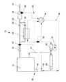
- the single figure shows a basic circuit of an exhaust gas purification system 10 for an internal combustion engine 12.
- the exhaust gas purification system 10 is accommodated in an exhaust line 14 of the internal combustion engine 12 and comprises components such as a pre-catalytic converter 16 and a NO x storage catalytic converter 18. Furthermore, the exhaust line 14 is in a partial area double flow, that is to say it has a bypass 20. An exhaust gas mass flow can be deflected in a manner to be explained in more detail via the switching means 22, 23.
- Optimal operation of the NO x storage catalytic converter 18 is highly temperature-dependent.
- a minimum temperature is required for the storage component, above which sufficient absorption of nitrogen oxides NO x emitted by the internal combustion engine 12 is made possible. Above a desorption temperature, however, the stored NO x is suddenly desorbed again.
- the catalyst component of the NO x storage catalytic converter 18 also only allows operation in a limited temperature range.
- a minimum activity temperature must be exceeded and, on the other hand, an excessively high temperature can lead to thermal damage to the NO x storage catalytic converter 18. In normal operation, a compromise must therefore be found between the optimal operating temperatures of the storage components and the catalyst component.
- a heat exchanger 24 is used to cool the exhaust gas Part of an exhaust gas cooling 26 arranged.
- the heat exchanger 24 is the Exhaust gas flows through if the switching means 23 remains in an open position.
- the A liquid coolant flows through the heat exchanger 24 corresponding to a flow rate and a temperature difference to the exhaust gas a calculable amount of heat is extracted from the exhaust gas or to the exhaust gas delivers.
- the exhaust gas cooling 26 further includes a cooler 28 and an additional cooler 30 Blower 32. Furthermore, an additional pump 34 is integrated in a coolant circuit 36.
- the cooler 28 is part of an engine cooling system 38, which consists of a water pump 40, a thermostat 42 and a coolant circuit 44.
- the engine cooling system 38 is used in a known manner to regulate an engine temperature Internal combustion engine 12 used, with the exhaust gas cooling 26 in addition now Area of the cooler 28 is connected to the engine cooling system 38.
- the Coolant circuit 36 opens into the coolant circuit 44, with outflow and inflow through the cooler 28 are separated.
- the auxiliary pump 34 can be designed as an electric pump and can be regulated in its delivery volume and / or its delivery direction.
- a coolant temperature and / or an exhaust gas temperature and / or a temperature of the NO x storage catalytic converter 18 can serve as reference variables for regulating the delivery volume and the delivery direction of the additional pump 34.
- These temperatures can be detected by a corresponding sensor system using the schematically illustrated temperature sensors 46, 47, 48 and transmitted to a control unit (not shown here) for the auxiliary pump 34.
- a procedure is stored in digital form in the control unit, which specifies a delivery volume to be set or a delivery direction to be set depending on the detected temperatures of the additional pump 34.
- the arrangement shown allows the operation of the exhaust gas cleaning system 10 to be optimized, for example, in the following operating situations:
- the engine speed usually works synchronously driven water pump 40 only with a low coolant flow in Coolant circuit 44.
- the switching means 22, 23 are set such that the exhaust gas mass flow through the heat exchanger 24 is passed.
- the auxiliary pump 34 is activated, which then increases the coolant flow within the coolant circuit 36.
- Such an approach can also be made dependent on whether the Exhaust gas temperature exceeds a predetermined minimum temperature.
- the delivery direction of the auxiliary pump 34 is determined so that the coolant is tapped off in front of the cooler 28. If the coolant temperature is still above that of the exhaust gas, it can thus be heated. For cooling can then reverse the delivery direction of the auxiliary pump 34 again become.
- a cooling capacity of the additional cooler 30 can be achieved by suitable control of a cooling air flow of the associated blower 32 varies and from the coolant temperature detected by the temperature sensor 46 be made dependent.
- the bypass 20 is closed by the switching means 23. In this way, overheating of the heat exchanger 24 can be avoided.
Landscapes
- Engineering & Computer Science (AREA)
- Chemical & Material Sciences (AREA)
- Combustion & Propulsion (AREA)
- Mechanical Engineering (AREA)
- General Engineering & Computer Science (AREA)
- Chemical Kinetics & Catalysis (AREA)
- Health & Medical Sciences (AREA)
- Toxicology (AREA)
- Exhaust Gas After Treatment (AREA)
Applications Claiming Priority (2)
| Application Number | Priority Date | Filing Date | Title |
|---|---|---|---|
| DE10012432A DE10012432A1 (de) | 2000-03-15 | 2000-03-15 | Abgasreinigungsanlage einer Verbrennungskraftmaschine mit einer Abgaskühlung und Verfahren zum Betrieb der Abgasreinigungsanlage |
| DE10012432 | 2000-03-15 |
Publications (3)
| Publication Number | Publication Date |
|---|---|
| EP1134367A2 true EP1134367A2 (fr) | 2001-09-19 |
| EP1134367A3 EP1134367A3 (fr) | 2004-01-02 |
| EP1134367B1 EP1134367B1 (fr) | 2005-08-10 |
Family
ID=7634702
Family Applications (1)
| Application Number | Title | Priority Date | Filing Date |
|---|---|---|---|
| EP01250017A Expired - Lifetime EP1134367B1 (fr) | 2000-03-15 | 2001-01-12 | Installation de purification de gaz d'échappement d'un moteur à combustion interne avec refroidissement de gaz d'échappement et procédé d'utilisation de l'installation de purification de gaz d'échappement |
Country Status (3)
| Country | Link |
|---|---|
| EP (1) | EP1134367B1 (fr) |
| AT (1) | ATE301768T1 (fr) |
| DE (2) | DE10012432A1 (fr) |
Cited By (5)
| Publication number | Priority date | Publication date | Assignee | Title |
|---|---|---|---|---|
| WO2002070872A3 (fr) * | 2001-03-01 | 2003-02-27 | Engelhard Corp | Appareil et procede de controle des emissions de vehicules |
| EP1403480A3 (fr) * | 2002-09-24 | 2004-04-28 | Hitachi Ltd. | Système de commande avec catalyseur pour purifier des gaz d'échappement |
| WO2004101962A1 (fr) * | 2003-03-14 | 2004-11-25 | Westport Research Inc. | Gestion des fluctuations thermiques dans des systemes de post-traitement utilisant un adsorbeur pauvre en nox |
| CN102953790A (zh) * | 2011-08-23 | 2013-03-06 | 通用汽车环球科技运作有限责任公司 | 有热量回收装置的内燃机排气装置及其工作方法 |
| CN111237034A (zh) * | 2020-03-13 | 2020-06-05 | 广州大华德盛热管理科技股份有限公司 | 陆用尾气降温装置及武器装备 |
Families Citing this family (1)
| Publication number | Priority date | Publication date | Assignee | Title |
|---|---|---|---|---|
| CN111188811A (zh) * | 2020-03-13 | 2020-05-22 | 广州大华德盛热管理科技股份有限公司 | 液压油预热装置及工程机械 |
Citations (2)
| Publication number | Priority date | Publication date | Assignee | Title |
|---|---|---|---|---|
| DE3918597A1 (de) | 1989-06-07 | 1990-12-13 | Schatz Oskar | Verfahren zum schadstoffarmen betrieb eines verbrennungsmotors |
| DE4410022A1 (de) | 1994-03-23 | 1995-10-05 | Siemens Ag | Abgasreinigungsanlage für eine Brennkraftmaschine |
Family Cites Families (5)
| Publication number | Priority date | Publication date | Assignee | Title |
|---|---|---|---|---|
| US3050935A (en) * | 1961-01-05 | 1962-08-28 | Socony Mobil Oil Co Inc | Apparatus for catalytically treating internal combustion engine exhaust gases |
| JP2902166B2 (ja) * | 1991-08-07 | 1999-06-07 | 三菱重工業株式会社 | 排気過給機付内燃機関の脱硝装置 |
| KR100227551B1 (ko) * | 1996-09-06 | 1999-11-01 | 정몽규 | 수냉식 엔진의 냉각장치 |
| FR2755727B1 (fr) * | 1996-11-08 | 1999-01-15 | Valeo Thermique Moteur Sa | Pot catalytique avec protection du catalyseur contre les hautes temperatures |
| GB2374029B (en) * | 1998-05-15 | 2002-12-31 | Arvinmeritor Inc | Exhaust system |
-
2000
- 2000-03-15 DE DE10012432A patent/DE10012432A1/de not_active Withdrawn
-
2001
- 2001-01-12 DE DE50107007T patent/DE50107007D1/de not_active Expired - Lifetime
- 2001-01-12 EP EP01250017A patent/EP1134367B1/fr not_active Expired - Lifetime
- 2001-01-12 AT AT01250017T patent/ATE301768T1/de not_active IP Right Cessation
Patent Citations (2)
| Publication number | Priority date | Publication date | Assignee | Title |
|---|---|---|---|---|
| DE3918597A1 (de) | 1989-06-07 | 1990-12-13 | Schatz Oskar | Verfahren zum schadstoffarmen betrieb eines verbrennungsmotors |
| DE4410022A1 (de) | 1994-03-23 | 1995-10-05 | Siemens Ag | Abgasreinigungsanlage für eine Brennkraftmaschine |
Cited By (6)
| Publication number | Priority date | Publication date | Assignee | Title |
|---|---|---|---|---|
| WO2002070872A3 (fr) * | 2001-03-01 | 2003-02-27 | Engelhard Corp | Appareil et procede de controle des emissions de vehicules |
| US6568179B2 (en) | 2001-03-01 | 2003-05-27 | Engelhard Corporation | Apparatus and method for vehicle emissions control |
| EP1403480A3 (fr) * | 2002-09-24 | 2004-04-28 | Hitachi Ltd. | Système de commande avec catalyseur pour purifier des gaz d'échappement |
| WO2004101962A1 (fr) * | 2003-03-14 | 2004-11-25 | Westport Research Inc. | Gestion des fluctuations thermiques dans des systemes de post-traitement utilisant un adsorbeur pauvre en nox |
| CN102953790A (zh) * | 2011-08-23 | 2013-03-06 | 通用汽车环球科技运作有限责任公司 | 有热量回收装置的内燃机排气装置及其工作方法 |
| CN111237034A (zh) * | 2020-03-13 | 2020-06-05 | 广州大华德盛热管理科技股份有限公司 | 陆用尾气降温装置及武器装备 |
Also Published As
| Publication number | Publication date |
|---|---|
| EP1134367B1 (fr) | 2005-08-10 |
| ATE301768T1 (de) | 2005-08-15 |
| EP1134367A3 (fr) | 2004-01-02 |
| DE50107007D1 (de) | 2005-09-15 |
| DE10012432A1 (de) | 2001-09-20 |
Similar Documents
| Publication | Publication Date | Title |
|---|---|---|
| DE4240239C2 (de) | Verbrennungskraftmaschine | |
| DE602004004016T2 (de) | Verfahren zur Ventilsteuerung eines Abgassystems | |
| EP0690210B1 (fr) | Procédé et dispositif de régénération commandée d'un filtre à particules diesel | |
| DE10319594A1 (de) | Turboladereinrichtung sowie ein Verfahren zum Betreiben einer Turboladereinrichtung | |
| EP1233466A2 (fr) | Système de refroidissement d'une installation à piles à combustible | |
| DE69801472T2 (de) | Abgasanlage für einen Kraftfahrzeugmotor | |
| DE102007021526A1 (de) | Abgaswärmenutzung zur beschleunigten Warmlaufphase bei Turbomotoren | |
| DE102017118455B4 (de) | Abgasnachbehandlungssystem für einen Verbrennungsmotor und Verfahren zur Abgasnachbehandlung eines Verbrennungsmotors | |
| DE112006001296T5 (de) | Auspufflinie für Brennkraftmotoren | |
| EP1177407B1 (fr) | Echangeur de chaleur pouvant etre commute | |
| EP1134367A2 (fr) | Installation de purification de gaz d'échappement d'un moteur à combustion interne avec refroidissement de gaz d'échappement et procédé d'utilisation de l'installation de purification de gaz d'échappement | |
| DE102010055915A1 (de) | Verfahren und Vorrichtung zur Verteilung eines Abgasstroms einer Brennkraftmaschine | |
| DE4310962C1 (de) | Gemeinsame Abgasanlage für mehrere Brennkraftmaschinen mit Entstickung des Abgases durch selektive katalytische Reduktion | |
| EP2924259A1 (fr) | Système de motopropulsion | |
| DE102004048338C5 (de) | Brennkraftmaschine | |
| EP1133623A1 (fr) | Circuit de refroidissement | |
| DE102013105094B4 (de) | Nachbehandlungsvorrichtung für eine Maschine | |
| EP2848478A2 (fr) | Commutateur de flux | |
| DE102010055914A1 (de) | Vorrichtung und Verfahren zur Verteilung eines Abgasstroms einer Brennkraftmaschine | |
| DE102008005275B4 (de) | Verfahren und Vorrichtung zum Betreiben eines Wärmetauschersystems für ein Kraftfahrzeug | |
| DE102018218871A1 (de) | Anordnung und Verfahren zur Verringerung der Kondensatbildung in einem Zuluftstrang eines Verbrennungsmotors sowie Kraftfahrzeug | |
| DE102015204090B3 (de) | Verfahren zum Betreiben eines Hybridantriebs und Hybridantrieb | |
| DE102011016642A1 (de) | Gasleitsystem für ein Kraftfahrzeug, Kraftfahrzeug mit einem solchen Gasleitsystem und Verfahren zum Betrieb eines Gasleitsystems in einem Kraftfahrzeug | |
| DE19939052B4 (de) | Verfahren zum Schalten zwischen zwei Betriebsmodi von wenigstens einem Nebenaggregat in einem Kraftfahrzeug | |
| EP1458959B1 (fr) | Procede pour la conception d'un systeme de refroidissement de gaz d'echappement |
Legal Events
| Date | Code | Title | Description |
|---|---|---|---|
| PUAI | Public reference made under article 153(3) epc to a published international application that has entered the european phase |
Free format text: ORIGINAL CODE: 0009012 |
|
| AK | Designated contracting states |
Kind code of ref document: A2 Designated state(s): AT BE CH CY DE DK ES FI FR GB GR IE IT LI LU MC NL PT SE TR |
|
| AX | Request for extension of the european patent |
Free format text: AL;LT;LV;MK;RO;SI |
|
| PUAL | Search report despatched |
Free format text: ORIGINAL CODE: 0009013 |
|
| AK | Designated contracting states |
Kind code of ref document: A3 Designated state(s): AT BE CH CY DE DK ES FI FR GB GR IE IT LI LU MC NL PT SE TR |
|
| AX | Request for extension of the european patent |
Extension state: AL LT LV MK RO SI |
|
| RIC1 | Information provided on ipc code assigned before grant |
Ipc: 7F 01N 3/20 B Ipc: 7F 01N 3/04 A Ipc: 7F 01N 5/02 B |
|
| 17P | Request for examination filed |
Effective date: 20040702 |
|
| AKX | Designation fees paid |
Designated state(s): AT BE CH CY DE DK ES FI FR GB GR IE IT LI LU MC NL PT SE TR |
|
| 17Q | First examination report despatched |
Effective date: 20040823 |
|
| GRAP | Despatch of communication of intention to grant a patent |
Free format text: ORIGINAL CODE: EPIDOSNIGR1 |
|
| RIN1 | Information on inventor provided before grant (corrected) |
Inventor name: ZILLMER, MICHAEL Inventor name: POTT, EKKEHARD, DR. Inventor name: ARENS, GUENTER |
|
| GRAS | Grant fee paid |
Free format text: ORIGINAL CODE: EPIDOSNIGR3 |
|
| GRAA | (expected) grant |
Free format text: ORIGINAL CODE: 0009210 |
|
| AK | Designated contracting states |
Kind code of ref document: B1 Designated state(s): AT BE CH CY DE DK ES FI FR GB GR IE IT LI LU MC NL PT SE TR |
|
| PG25 | Lapsed in a contracting state [announced via postgrant information from national office to epo] |
Ref country code: GB Free format text: LAPSE BECAUSE OF FAILURE TO SUBMIT A TRANSLATION OF THE DESCRIPTION OR TO PAY THE FEE WITHIN THE PRESCRIBED TIME-LIMIT Effective date: 20050810 Ref country code: TR Free format text: LAPSE BECAUSE OF FAILURE TO SUBMIT A TRANSLATION OF THE DESCRIPTION OR TO PAY THE FEE WITHIN THE PRESCRIBED TIME-LIMIT Effective date: 20050810 Ref country code: NL Free format text: LAPSE BECAUSE OF FAILURE TO SUBMIT A TRANSLATION OF THE DESCRIPTION OR TO PAY THE FEE WITHIN THE PRESCRIBED TIME-LIMIT Effective date: 20050810 Ref country code: FI Free format text: LAPSE BECAUSE OF FAILURE TO SUBMIT A TRANSLATION OF THE DESCRIPTION OR TO PAY THE FEE WITHIN THE PRESCRIBED TIME-LIMIT Effective date: 20050810 Ref country code: IE Free format text: LAPSE BECAUSE OF FAILURE TO SUBMIT A TRANSLATION OF THE DESCRIPTION OR TO PAY THE FEE WITHIN THE PRESCRIBED TIME-LIMIT Effective date: 20050810 Ref country code: IT Free format text: LAPSE BECAUSE OF FAILURE TO SUBMIT A TRANSLATION OF THE DESCRIPTION OR TO PAY THE FEE WITHIN THE PRESCRIBED TIME-LIMIT;WARNING: LAPSES OF ITALIAN PATENTS WITH EFFECTIVE DATE BEFORE 2007 MAY HAVE OCCURRED AT ANY TIME BEFORE 2007. THE CORRECT EFFECTIVE DATE MAY BE DIFFERENT FROM THE ONE RECORDED. Effective date: 20050810 |
|
| REG | Reference to a national code |
Ref country code: GB Ref legal event code: FG4D Free format text: NOT ENGLISH |
|
| REG | Reference to a national code |
Ref country code: CH Ref legal event code: EP |
|
| REG | Reference to a national code |
Ref country code: IE Ref legal event code: FG4D Free format text: LANGUAGE OF EP DOCUMENT: GERMAN |
|
| REF | Corresponds to: |
Ref document number: 50107007 Country of ref document: DE Date of ref document: 20050915 Kind code of ref document: P |
|
| PG25 | Lapsed in a contracting state [announced via postgrant information from national office to epo] |
Ref country code: GR Free format text: LAPSE BECAUSE OF FAILURE TO SUBMIT A TRANSLATION OF THE DESCRIPTION OR TO PAY THE FEE WITHIN THE PRESCRIBED TIME-LIMIT Effective date: 20051110 Ref country code: DK Free format text: LAPSE BECAUSE OF FAILURE TO SUBMIT A TRANSLATION OF THE DESCRIPTION OR TO PAY THE FEE WITHIN THE PRESCRIBED TIME-LIMIT Effective date: 20051110 Ref country code: SE Free format text: LAPSE BECAUSE OF FAILURE TO SUBMIT A TRANSLATION OF THE DESCRIPTION OR TO PAY THE FEE WITHIN THE PRESCRIBED TIME-LIMIT Effective date: 20051110 |
|
| PG25 | Lapsed in a contracting state [announced via postgrant information from national office to epo] |
Ref country code: ES Free format text: LAPSE BECAUSE OF FAILURE TO SUBMIT A TRANSLATION OF THE DESCRIPTION OR TO PAY THE FEE WITHIN THE PRESCRIBED TIME-LIMIT Effective date: 20051121 |
|
| PG25 | Lapsed in a contracting state [announced via postgrant information from national office to epo] |
Ref country code: PT Free format text: LAPSE BECAUSE OF FAILURE TO SUBMIT A TRANSLATION OF THE DESCRIPTION OR TO PAY THE FEE WITHIN THE PRESCRIBED TIME-LIMIT Effective date: 20060110 |
|
| PG25 | Lapsed in a contracting state [announced via postgrant information from national office to epo] |
Ref country code: AT Free format text: LAPSE BECAUSE OF NON-PAYMENT OF DUE FEES Effective date: 20060112 |
|
| PG25 | Lapsed in a contracting state [announced via postgrant information from national office to epo] |
Ref country code: LI Free format text: LAPSE BECAUSE OF NON-PAYMENT OF DUE FEES Effective date: 20060131 Ref country code: LU Free format text: LAPSE BECAUSE OF NON-PAYMENT OF DUE FEES Effective date: 20060131 Ref country code: MC Free format text: LAPSE BECAUSE OF NON-PAYMENT OF DUE FEES Effective date: 20060131 Ref country code: CH Free format text: LAPSE BECAUSE OF NON-PAYMENT OF DUE FEES Effective date: 20060131 Ref country code: BE Free format text: LAPSE BECAUSE OF NON-PAYMENT OF DUE FEES Effective date: 20060131 |
|
| NLV1 | Nl: lapsed or annulled due to failure to fulfill the requirements of art. 29p and 29m of the patents act | ||
| GBV | Gb: ep patent (uk) treated as always having been void in accordance with gb section 77(7)/1977 [no translation filed] |
Effective date: 20050810 |
|
| REG | Reference to a national code |
Ref country code: IE Ref legal event code: FD4D |
|
| PLBE | No opposition filed within time limit |
Free format text: ORIGINAL CODE: 0009261 |
|
| STAA | Information on the status of an ep patent application or granted ep patent |
Free format text: STATUS: NO OPPOSITION FILED WITHIN TIME LIMIT |
|
| 26N | No opposition filed |
Effective date: 20060511 |
|
| PG25 | Lapsed in a contracting state [announced via postgrant information from national office to epo] |
Ref country code: FR Free format text: LAPSE BECAUSE OF FAILURE TO SUBMIT A TRANSLATION OF THE DESCRIPTION OR TO PAY THE FEE WITHIN THE PRESCRIBED TIME-LIMIT Effective date: 20060811 |
|
| REG | Reference to a national code |
Ref country code: CH Ref legal event code: PL |
|
| EN | Fr: translation not filed | ||
| BERE | Be: lapsed |
Owner name: VOLKSWAGEN A.G. Effective date: 20060131 |
|
| PG25 | Lapsed in a contracting state [announced via postgrant information from national office to epo] |
Ref country code: CY Free format text: LAPSE BECAUSE OF FAILURE TO SUBMIT A TRANSLATION OF THE DESCRIPTION OR TO PAY THE FEE WITHIN THE PRESCRIBED TIME-LIMIT Effective date: 20050810 Ref country code: FR Free format text: LAPSE BECAUSE OF FAILURE TO SUBMIT A TRANSLATION OF THE DESCRIPTION OR TO PAY THE FEE WITHIN THE PRESCRIBED TIME-LIMIT Effective date: 20050810 |
|
| PGFP | Annual fee paid to national office [announced via postgrant information from national office to epo] |
Ref country code: DE Payment date: 20200131 Year of fee payment: 20 |
|
| REG | Reference to a national code |
Ref country code: DE Ref legal event code: R071 Ref document number: 50107007 Country of ref document: DE |
|
| P01 | Opt-out of the competence of the unified patent court (upc) registered |
Effective date: 20230523 |