EP1134399A2 - Verfahren und Vorrichtung zur Druckregelung - Google Patents
Verfahren und Vorrichtung zur Druckregelung Download PDFInfo
- Publication number
- EP1134399A2 EP1134399A2 EP00125558A EP00125558A EP1134399A2 EP 1134399 A2 EP1134399 A2 EP 1134399A2 EP 00125558 A EP00125558 A EP 00125558A EP 00125558 A EP00125558 A EP 00125558A EP 1134399 A2 EP1134399 A2 EP 1134399A2
- Authority
- EP
- European Patent Office
- Prior art keywords
- pressure
- model
- control
- variable
- disturbance
- Prior art date
- Legal status (The legal status is an assumption and is not a legal conclusion. Google has not performed a legal analysis and makes no representation as to the accuracy of the status listed.)
- Granted
Links
- 238000000034 method Methods 0.000 title claims abstract description 17
- 238000002347 injection Methods 0.000 claims abstract description 19
- 239000007924 injection Substances 0.000 claims abstract description 19
- 230000009467 reduction Effects 0.000 claims description 5
- 230000001105 regulatory effect Effects 0.000 abstract description 4
- 239000000446 fuel Substances 0.000 description 14
- 238000010586 diagram Methods 0.000 description 9
- 238000012544 monitoring process Methods 0.000 description 5
- 238000002485 combustion reaction Methods 0.000 description 3
- 230000004913 activation Effects 0.000 description 2
- 230000008901 benefit Effects 0.000 description 2
- 230000006870 function Effects 0.000 description 2
- 230000008569 process Effects 0.000 description 2
- 230000003213 activating effect Effects 0.000 description 1
- 238000013459 approach Methods 0.000 description 1
- 230000005540 biological transmission Effects 0.000 description 1
- 230000001276 controlling effect Effects 0.000 description 1
- 230000003111 delayed effect Effects 0.000 description 1
- 230000001419 dependent effect Effects 0.000 description 1
- 238000001514 detection method Methods 0.000 description 1
- 230000006872 improvement Effects 0.000 description 1
- 238000012545 processing Methods 0.000 description 1
- 238000005086 pumping Methods 0.000 description 1
- 230000003362 replicative effect Effects 0.000 description 1
- 238000004088 simulation Methods 0.000 description 1
- 238000012546 transfer Methods 0.000 description 1
Images




Classifications
-
- F—MECHANICAL ENGINEERING; LIGHTING; HEATING; WEAPONS; BLASTING
- F02—COMBUSTION ENGINES; HOT-GAS OR COMBUSTION-PRODUCT ENGINE PLANTS
- F02D—CONTROLLING COMBUSTION ENGINES
- F02D41/00—Electrical control of supply of combustible mixture or its constituents
- F02D41/30—Controlling fuel injection
- F02D41/38—Controlling fuel injection of the high pressure type
- F02D41/3809—Common rail control systems
- F02D41/3836—Controlling the fuel pressure
- F02D41/3845—Controlling the fuel pressure by controlling the flow into the common rail, e.g. the amount of fuel pumped
-
- F—MECHANICAL ENGINEERING; LIGHTING; HEATING; WEAPONS; BLASTING
- F02—COMBUSTION ENGINES; HOT-GAS OR COMBUSTION-PRODUCT ENGINE PLANTS
- F02D—CONTROLLING COMBUSTION ENGINES
- F02D41/00—Electrical control of supply of combustible mixture or its constituents
- F02D41/22—Safety or indicating devices for abnormal conditions
- F02D41/221—Safety or indicating devices for abnormal conditions relating to the failure of actuators or electrically driven elements
-
- F—MECHANICAL ENGINEERING; LIGHTING; HEATING; WEAPONS; BLASTING
- F02—COMBUSTION ENGINES; HOT-GAS OR COMBUSTION-PRODUCT ENGINE PLANTS
- F02M—SUPPLYING COMBUSTION ENGINES IN GENERAL WITH COMBUSTIBLE MIXTURES OR CONSTITUENTS THEREOF
- F02M63/00—Other fuel-injection apparatus having pertinent characteristics not provided for in groups F02M39/00 - F02M57/00 or F02M67/00; Details, component parts, or accessories of fuel-injection apparatus, not provided for in, or of interest apart from, the apparatus of groups F02M39/00 - F02M61/00 or F02M67/00; Combination of fuel pump with other devices, e.g. lubricating oil pump
- F02M63/02—Fuel-injection apparatus having several injectors fed by a common pumping element, or having several pumping elements feeding a common injector; Fuel-injection apparatus having provisions for cutting-out pumps, pumping elements, or injectors; Fuel-injection apparatus having provisions for variably interconnecting pumping elements and injectors alternatively
- F02M63/0225—Fuel-injection apparatus having a common rail feeding several injectors ; Means for varying pressure in common rails; Pumps feeding common rails
-
- F—MECHANICAL ENGINEERING; LIGHTING; HEATING; WEAPONS; BLASTING
- F02—COMBUSTION ENGINES; HOT-GAS OR COMBUSTION-PRODUCT ENGINE PLANTS
- F02D—CONTROLLING COMBUSTION ENGINES
- F02D41/00—Electrical control of supply of combustible mixture or its constituents
- F02D41/02—Circuit arrangements for generating control signals
- F02D41/14—Introducing closed-loop corrections
- F02D41/1401—Introducing closed-loop corrections characterised by the control or regulation method
- F02D2041/1413—Controller structures or design
- F02D2041/1415—Controller structures or design using a state feedback or a state space representation
- F02D2041/1416—Observer
-
- F—MECHANICAL ENGINEERING; LIGHTING; HEATING; WEAPONS; BLASTING
- F02—COMBUSTION ENGINES; HOT-GAS OR COMBUSTION-PRODUCT ENGINE PLANTS
- F02D—CONTROLLING COMBUSTION ENGINES
- F02D41/00—Electrical control of supply of combustible mixture or its constituents
- F02D41/02—Circuit arrangements for generating control signals
- F02D41/14—Introducing closed-loop corrections
- F02D41/1401—Introducing closed-loop corrections characterised by the control or regulation method
- F02D2041/1433—Introducing closed-loop corrections characterised by the control or regulation method using a model or simulation of the system
-
- F—MECHANICAL ENGINEERING; LIGHTING; HEATING; WEAPONS; BLASTING
- F02—COMBUSTION ENGINES; HOT-GAS OR COMBUSTION-PRODUCT ENGINE PLANTS
- F02D—CONTROLLING COMBUSTION ENGINES
- F02D41/00—Electrical control of supply of combustible mixture or its constituents
- F02D41/22—Safety or indicating devices for abnormal conditions
- F02D2041/224—Diagnosis of the fuel system
-
- F—MECHANICAL ENGINEERING; LIGHTING; HEATING; WEAPONS; BLASTING
- F02—COMBUSTION ENGINES; HOT-GAS OR COMBUSTION-PRODUCT ENGINE PLANTS
- F02D—CONTROLLING COMBUSTION ENGINES
- F02D41/00—Electrical control of supply of combustible mixture or its constituents
- F02D41/22—Safety or indicating devices for abnormal conditions
- F02D2041/224—Diagnosis of the fuel system
- F02D2041/225—Leakage detection
-
- F—MECHANICAL ENGINEERING; LIGHTING; HEATING; WEAPONS; BLASTING
- F02—COMBUSTION ENGINES; HOT-GAS OR COMBUSTION-PRODUCT ENGINE PLANTS
- F02D—CONTROLLING COMBUSTION ENGINES
- F02D2200/00—Input parameters for engine control
- F02D2200/02—Input parameters for engine control the parameters being related to the engine
- F02D2200/06—Fuel or fuel supply system parameters
- F02D2200/0602—Fuel pressure
-
- F—MECHANICAL ENGINEERING; LIGHTING; HEATING; WEAPONS; BLASTING
- F02—COMBUSTION ENGINES; HOT-GAS OR COMBUSTION-PRODUCT ENGINE PLANTS
- F02D—CONTROLLING COMBUSTION ENGINES
- F02D2250/00—Engine control related to specific problems or objectives
- F02D2250/31—Control of the fuel pressure
Definitions
- the invention relates to a method and an apparatus for Pressure control, especially for a common rail system the preamble of claim 1.
- WO 96/03577 describes a system for controlling and regulating the Injection pressure of an internal combustion engine is known, in which a Pumping fuel under high pressure into a rail.
- the rail has a number of outlets that start with corresponding injectors are connected.
- the system exists from a pressure regulator, located between the outlet of the Pump and the entrance of the rail and the one Control signal is applied, which from a controller can be specified.
- the pressure control according to the invention for a common rail system has the advantage that with a model for rail pressure control the hydraulic disturbance variable dQs / dt can be recorded. So that is on the one hand, a quickly responsive monitoring for a Leakage in the high pressure area of a common rail system entire operating range possible. On the other hand, one can improved dynamics of the rail pressure control by activating the Disturbance variable can be achieved on the manipulated variable.
- Model a pressure regulator and / or an actuator Pressure control loop is modeled, and that the model provides at least one signal that the disturbances of the Characterized pressure control loop.
- the procedure according to the invention is particularly advantageous in systems in which an injection quantity QK, a Leakage amount QL, a control amount QS and a pressure reduction amount act as disturbances on the pressure control loop.
- the model includes at least one model for the actuator, preferably as a volume controlled high pressure pump is trained. With such a high pressure pump, the compressed amount of fuel and thus in the Pressure storage, which is also referred to as rail, promoted Control the amount of fuel.
- the model includes at least one model for the Controlled system, which is also referred to as a controlled system model.
- the rail is considered. In the simplest An integrator is used to model the rail.
- the disturbance variable determined using the model is used for detection a leak and / or to form an activation variable for the Control loop.
- the amount of fuel injected can be in the Disturbance variable may be included. But it can also be provided that the disturbance is not the amount of fuel injected includes.
- FIG. 1 shows a system overview of a common rail system
- 2 shows a block diagram of a pressure regulator
- FIG. 3 a block diagram of a model of the pressure regulator circuit
- Fig. 4 to 6 block diagrams of different variants of the Model
- Fig. 7 is a block diagram of a leakage monitoring by means of an observed disturbance variable
- FIG. 8 Block diagram of an improved pressure regulator with intrusion the observed disturbance.
- 1 shows a controllable reference number 1 High pressure pump.
- 2 is a valve that connects to the intake pipe of the Tanks 4 is operatively connected via the filter 5.
- 3 is a Fuel filter. 6 is a gear pump. 7 is the Metering unit. 8 is the pressure relief valve, 9 is the rail, 10 is a rail pressure sensor, 11 is a flow restrictor, 12 are Injectors, 13 is the accelerator pedal, 14 is the transducer of the Crankshaft revolution, 15 the pickup of the Camshaft revolution, 16 is the control unit for injection or / and ignition. 17 are other actuators, for example for exhaust gas recirculation and 18 are other sensors.
- FIG. 1 shows a Common rail system with pressure control via a quantity controlled High pressure pump 1 and optionally an additional one Pressure relief valve 8.
- the pressure is controlled via the solenoid valve controlled proportional valve, which also as Zumeßtechnik 7 is referred to, which the inflow to High pressure pump 1 according to the control variable sets.
- the fuel passes through the fuel filter 3 Metering unit 7. Depending on that on the metering unit adjustable control variable reaches an adjustable Amount of fuel in the high-pressure nozzle. From there the Fuel is pumped into rail 9 under high pressure. About the Injectors 12 get the fuel into the internal combustion engine.
- the control unit 16 controls the metering unit 7, the injectors 12, further actuators 17 and possibly the pressure relief valve 8 depending on the signals from sensors 13 to 15.
- Fig. 2 shows a block diagram of a pressure regulator.
- a controller At 20 is designated a controller. This is via a link point the difference between a Pist actual value and a setpoint Psoll fed for the rail pressure.
- the controller 20 provides one Manipulated variable PRail, should, at a node at which The second input of the connection point is a pre-control value dQvs / dt.
- the output signal of the node becomes passed to an actuator 21.
- the controller is preferably an element of the control unit 16.
- the setpoint Psoll and the pilot control value dQvs / dt depending on different operating parameters, preferably depending on the speed of the internal combustion engine and one that quantity to be injected characterizing quantity of fuel, given.
- the actuator 21 is preferably the controllable high-pressure pump 1, the metering unit 7 being acted upon by the manipulated variable.
- the metering unit 7 is preferably designed as a solenoid valve which, depending on the signal applied to it, supplies a certain amount of fuel to the high-pressure pump.
- the high pressure pump delivers the actual value of the delivery rate dQ HDP, is / dt of the high pressure pump into the rail. This quantity is reduced by the disturbance variables dQ L / dt, dQ s / dt, dQ DAV / dt and the injection quantity dQ I / dt. This results in the quantity dQ rail actually conveyed into the rail, ist / dt. This is done by a downstream of the actuator
- the block diagram of FIG. 2 is intended to clarify that several disturbance variables attack behind the actuator 21. These are the injection quantity dQ I / dt, the leakage quantity dQ L / dt, the control quantity of the injectors dQ s / dt and the pressure reduction quantity dQ DAV / dt that flows through the pressure reduction valve. Apart from the injection quantity, these variables are initially unknown in the engine control unit. With knowledge of these disturbance variables, the dynamic behavior of the pressure regulator could be improved on the one hand, and leakage monitoring of the high pressure area on the other hand.
- the disturbance variable dQ K / dt corresponds to the injection quantity.
- the manipulated variable of the pressure controller dQ HDP, target > 0 the sum of the disturbance variables can be estimated using this manipulated variable.
- the disadvantage here is that the estimated disturbance variable is coupled to the dynamics of the pressure control.
- the procedure according to the invention allows the previously Described common rail system with pressure control via a quantity controlled high pressure pump and optionally one additional pressure relief valve the disturbances in the pressure control loop (Leakage quantity, control quantity, injection quantity, pressure reduction quantity) to determine constantly. This means that at every operating point Known disturbances and it can on the one hand the dynamics of the Pressure control can be improved and secondly a permanent one Leakage monitoring of the high pressure area is carried out.
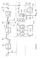
- FIG. 3 shows the structure of an embodiment of the model.
- This structure essentially consists of a series connection of a process model 21.0 of the actuator 21 and a process model 22.0 of the controlled system.
- the simulation PB of the controlled variable P is present at the output of this model.
- the input signal dQ HDP, Soll / dt of the actuator 21 is supplied to the actuator model 21.0 as an input variable.
- Actuator model 21.0 applies a node to its output signal.
- the output signal of the connection point 30 reaches the route model 22.0.
- the modeled controlled variable P B is present at the output of the line model 22.0. This is compared in a node 31 with the real controlled variable P ist .
- the difference between the modeled and the real controlled variable comes to different factor specifications 29.1, 29.2, 29.n, 29.10 and 29.11.
- the factor specifications 29.1, 29.2 and 29.n apply the actuator model and the factor specifications 29.10 and 29.11 apply signals to the connection point 30.
- the modeled disturbance variable QB is present at the output of factor specification 29.11.
- the factor specifications 29.1, 29.2 and 29.n give sizes gl, g2, gn before the transmission behavior of the actuator model affect, depending on the difference between the modeled and the real control variable. This means that Actuator model is dependent on the deviation between the modeled and adapted to the real control variable.
- a proportional factor is marked with 29.10, 29.11 represents an integrator with T ⁇ as the integrator time constant represents.
- 29.10 is a P-term and 29.11 an I-link.
- the route model 22.0 simulates the rail 9 and points in essentially an integrating behavior.
- the actuator model 21.0 essentially contains delay elements that the Behavior of the electrical output stage, the solenoid valve 7 and the delayed flow of the high pressure pump mark.
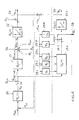
- FIG. 4 shows a second variant proposal for a Pressure control loop with an observer structure.
- This model differs from the embodiment of FIG. 3 in essential only in that the total disturbance is not that Output signal of the link 29.11 but the sum of the Output signals of elements 29.10 and 29.11 as total disturbance variable QB is used.
- 5 shows a further alternative possibility of the observer structure. 5 differs essentially from the previous embodiment in that the actuator 21 is divided into a current controller 21a and the actual actuator 21b.
- the signal dQ HDP, Soll / dt is fed to the controller 21a as a setpoint, the current IMPROP actually flowing through the solenoid valve 7 is fed back to the controller 21a as an actual value by the actuator 21b.
- the controller 21a Based on the comparison between the actual value and the target value for the current through the solenoid valve, the controller 21a forms a manipulated variable UMPROP to act upon the actuator 21b.
- FIG. 6 shows a further alternative to the observer structure.
- the actuator model with the Actual value UMPROP of the current regulator 32 is applied. Through this Procedure can continue the order of the observer be reduced.
- a block 34 specifies a maximum value b for the sum a from the control and leakage quantity.
- the sum a from the control and leakage amount calculated by a node is then compared in a comparator 35 according to FIG. 7 with this maximum value b.
- an error is detected in block 36 if the sum of the leakage quantity and the control quantity exceeds the maximum value.
- it can also be provided that an error is recognized when the modeled disturbance variable dQ B / dt exceeds a threshold value.
- the modeled disturbance variable dQ B / dt an improvement in the dynamics of the pressure regulator is possible.
- this variable is taken into account at a suitable point in the control loop. This has the advantage that the disturbance variable does not have to be corrected by the controller.
- the disturbance variable is compensated dynamically by the observer variable.
- FIG. 8 A corresponding embodiment is shown in FIG. 8. There, the pressure regulator is as in FIG. 2 as Block diagram shown. Corresponding elements are included designated with corresponding reference numerals. The single ones Interference variables are generally referred to as dQo / dt.
- the pilot control value dQ vs / dt is specified as a function of the injection quantity dQ K / dt.
- an intrusion variable dQ Auf / dt is added to the output signal of the pressure regulator 20 in a further node.
- the disturbance variable is taken into account when forming the pilot control variable dQ vs / dt.
Landscapes
- Engineering & Computer Science (AREA)
- Chemical & Material Sciences (AREA)
- Combustion & Propulsion (AREA)
- Mechanical Engineering (AREA)
- General Engineering & Computer Science (AREA)
- Electrical Control Of Air Or Fuel Supplied To Internal-Combustion Engine (AREA)
- Combined Controls Of Internal Combustion Engines (AREA)
- Fuel-Injection Apparatus (AREA)
- Control Of Fluid Pressure (AREA)
Abstract
Description
Claims (9)
- Verfahren zur Druckregelung, insbesondere bei einem Common-Rail-System, mit einer mengengesteuerten Hochdruckpumpe und/oder einem Druckabbauventil, dadurch gekennzeichnet, daß mittels eines Modells ein Druckregler und/oder ein Stellelement eines Druckregelkreises nachgebildet wird, und das Modell wenigstens ein Signal liefert, das die Störgrößen des Druckregelkreises charakterisiert.
- Verfahren nach Anspruch 1, dadurch gekennzeichnet, daß eine Einspritzmenge, eine Leckagemenge, eine Steuermenge und eine Druckabbaumenge als Störgrößen auf den Druckregelkreis einwirken.
- Verfahren nach Anspruch 1, dadurch gekennzeichnet, daß mittels des Modells die Summe der einzelnen Störgrößen wie Einspritzmenge, Leckagemenge, Steuermenge und/oder Menge des Druckabbauventils bestimmbar ist und aus der Kenntnis dieser Größen die Leckagemenge bestimmbar ist.
- Verfahren nach einem der vorherigen Ansprüche, dadurch gekennzeichnet, daß das Modell wenigstens ein Stellermodell und ein Streckenmodell beinhaltet.
- Verfahren nach einem der Ansprüche 1 bis 4, dadurch gekennzeichnet, daß das Stellermodell wenigstens einen Steller und das Streckenmodel wenigstens einen Druckspeicher nachbildet.
- Verfahren nach Anspruch 5, dadurch gekennzeichnet, daß das Streckenmodell wenigstens integrierendes Verhalten aufweist.
- Verfahren nach einem der Ansprüche 1 bis 6, dadurch gekennzeichnet, daß die Störgröße zur Erkennung einer Leckage verwendbar ist.
- Verfahren nach einem der Ansprüche 1 bis 7, dadurch gekennzeichnet, daß die Störgröße zur Bildung einer Aufschaltgröße für den Regelkreis verwendbar ist.
- Vorrichtung zur Druckregelung, insbesondere bei einem Common-Rail-System, mit einer mengengesteuerten Hochdruckpumpe und/oder einem Druckabbauventil, dadurch gekennzeichnet, daß als ein Modell ein Druckregler und/oder ein Stellelement eines Druckregelkreises nachgebildet wird, und daß das Modell wenigstens ein Signal liefert, das die Störgrößen des Druckregelkreises charakterisiert.
Applications Claiming Priority (2)
| Application Number | Priority Date | Filing Date | Title |
|---|---|---|---|
| DE2000103298 DE10003298A1 (de) | 2000-01-27 | 2000-01-27 | Verfahren und Vorrichtung zur Druckregelung |
| DE10003298 | 2000-01-27 |
Publications (3)
| Publication Number | Publication Date |
|---|---|
| EP1134399A2 true EP1134399A2 (de) | 2001-09-19 |
| EP1134399A3 EP1134399A3 (de) | 2002-06-19 |
| EP1134399B1 EP1134399B1 (de) | 2006-02-08 |
Family
ID=7628771
Family Applications (1)
| Application Number | Title | Priority Date | Filing Date |
|---|---|---|---|
| EP20000125558 Expired - Lifetime EP1134399B1 (de) | 2000-01-27 | 2000-11-22 | Verfahren und Vorrichtung zur Druckregelung |
Country Status (2)
| Country | Link |
|---|---|
| EP (1) | EP1134399B1 (de) |
| DE (2) | DE10003298A1 (de) |
Cited By (3)
| Publication number | Priority date | Publication date | Assignee | Title |
|---|---|---|---|---|
| WO2002081892A1 (en) * | 2001-04-03 | 2002-10-17 | Caterpillar Inc. | Model based rail pressure control for a hydraulic system with a variable delivery pump |
| EP1486658A3 (de) * | 2003-06-12 | 2005-05-25 | Robert Bosch Gmbh | Fehlerdiagnoseverfahren und -vorrichtung für ein Kraftfahrzeugsystem |
| EP1310655A3 (de) * | 2001-11-07 | 2006-10-25 | Denso Corporation | Kraftstoffeinspritzeinrichtung |
Families Citing this family (8)
| Publication number | Priority date | Publication date | Assignee | Title |
|---|---|---|---|---|
| DE10157641C2 (de) | 2001-11-24 | 2003-09-25 | Mtu Friedrichshafen Gmbh | Verfahren zur Steuerung einer Brennkraftmaschine |
| JP2004353487A (ja) * | 2003-05-27 | 2004-12-16 | Mitsubishi Electric Corp | 内燃機関の燃料供給装置 |
| EP1790844A1 (de) * | 2005-11-25 | 2007-05-30 | Delphi Technologies, Inc. | Verfahren zur Identifizierung vom abnormalen Verhalten eines Dynamischen Systems |
| DE102008048193B4 (de) * | 2008-09-20 | 2023-05-04 | Volkswagen Ag | Verfahren zum Bestimmen eines Vorsteuerwertes für ein Kraftstoffeinspritzsystem einer Brennkraftmaschine |
| DE102009050467B4 (de) | 2009-10-23 | 2017-04-06 | Mtu Friedrichshafen Gmbh | Verfahren zur Steuerung und Regelung einer Brennkraftmaschine |
| DE102009050468B4 (de) | 2009-10-23 | 2017-03-16 | Mtu Friedrichshafen Gmbh | Verfahren zur Steuerung und Regelung einer Brennkraftmaschine |
| DE102011083628A1 (de) * | 2011-09-28 | 2013-03-28 | Continental Automotive Gmbh | Speichereinspritzsystem und Verfahren zur Druckregelung eines Speichereinspritzsystems |
| DE102014206717B4 (de) | 2014-04-08 | 2022-10-20 | Vitesco Technologies GmbH | Druckspeichereinrichtung für ein Kraftfahrzeug-Kraftstoff-Einspritzsystem, sowie Verfahren zum Betrieb einer derartigen Druckspeichereinrichtung |
Citations (1)
| Publication number | Priority date | Publication date | Assignee | Title |
|---|---|---|---|---|
| WO1996003577A1 (en) | 1994-07-22 | 1996-02-08 | C.R.F. Societa' Consortile Per Azioni | Dynamic electronic control system for controlling the injection pressure of a rail injection system |
Family Cites Families (3)
| Publication number | Priority date | Publication date | Assignee | Title |
|---|---|---|---|---|
| US5609136A (en) * | 1994-06-28 | 1997-03-11 | Cummins Engine Company, Inc. | Model predictive control for HPI closed-loop fuel pressure control system |
| US5992229A (en) * | 1996-02-05 | 1999-11-30 | Neles-Jamesbury Oy | Method and equipment for determining the performance of control valve |
| DE19757655C2 (de) * | 1997-12-23 | 2002-09-26 | Siemens Ag | Verfahren und Vorrichtung zur Funktionsüberwachung eines Drucksensors |
-
2000
- 2000-01-27 DE DE2000103298 patent/DE10003298A1/de not_active Withdrawn
- 2000-11-22 EP EP20000125558 patent/EP1134399B1/de not_active Expired - Lifetime
- 2000-11-22 DE DE50012187T patent/DE50012187D1/de not_active Expired - Lifetime
Patent Citations (1)
| Publication number | Priority date | Publication date | Assignee | Title |
|---|---|---|---|---|
| WO1996003577A1 (en) | 1994-07-22 | 1996-02-08 | C.R.F. Societa' Consortile Per Azioni | Dynamic electronic control system for controlling the injection pressure of a rail injection system |
Cited By (4)
| Publication number | Priority date | Publication date | Assignee | Title |
|---|---|---|---|---|
| WO2002081892A1 (en) * | 2001-04-03 | 2002-10-17 | Caterpillar Inc. | Model based rail pressure control for a hydraulic system with a variable delivery pump |
| EP1310655A3 (de) * | 2001-11-07 | 2006-10-25 | Denso Corporation | Kraftstoffeinspritzeinrichtung |
| EP1486658A3 (de) * | 2003-06-12 | 2005-05-25 | Robert Bosch Gmbh | Fehlerdiagnoseverfahren und -vorrichtung für ein Kraftfahrzeugsystem |
| US7765042B2 (en) | 2003-06-12 | 2010-07-27 | Robert Bosch Gmbh | Fault diagnostic method and device |
Also Published As
| Publication number | Publication date |
|---|---|
| DE50012187D1 (de) | 2006-04-20 |
| DE10003298A1 (de) | 2001-08-02 |
| EP1134399B1 (de) | 2006-02-08 |
| EP1134399A3 (de) | 2002-06-19 |
Similar Documents
| Publication | Publication Date | Title |
|---|---|---|
| EP1303693B1 (de) | Verfahren und vorrichtung zur steuerung einer brennkraftmaschine | |
| DE19618932A1 (de) | Vorrichtung und Verfahren zur Regelung des Kraftstoffes in einem Hochdruckspeicher | |
| DE102011052138A1 (de) | Steuervorrichtung für Druckreduzierventile | |
| EP3481686B1 (de) | Vorrichtung und verfahren zur ventilansteuerung | |
| DE10316391A1 (de) | Verfahren zum Betreiben einer Brennkraftmaschine insbesondere eines Kraftfahrzeugs | |
| EP1134399B1 (de) | Verfahren und Vorrichtung zur Druckregelung | |
| EP1613852B1 (de) | Verfahren zum betreiben eines verbrennungsmotors mit einer drehmoment berwachung | |
| DE102007050026B4 (de) | Verfahren und Vorrichtung zum Überwachen von Steuer- und Regelkreisen in einem Motorsystem | |
| DE102009028650A1 (de) | Verfahren zum Betreiben eines Kraftstoff-Einspritzventils einer Brennkraftmaschine | |
| DE102009007365A1 (de) | Fehleranalyseverfahren und Fehleranalysevorrichtung für einen Verbrennungsmotor | |
| DE10123035A1 (de) | Verfahren und Vorrichtung zur Steuerung einer Brennkraftmaschine | |
| DE102005020686A1 (de) | Verfahren zum Steuern einer Kraftstoffzuführeinrichtung einer Brennkraftmaschine | |
| DE102018214411A1 (de) | Verfahren zum Ermitteln eines charakteristischen Zeitpunktes eines Einspritzvorgangs eines Kraftstoffinjektors | |
| DE10303573B4 (de) | Verfahren, Computerprogramm, Speichermedium und Steuer- und/oder Regelgerät zum Betreiben einer Brennkraftmaschine, sowie Brennkraftmaschine insbesondere für ein Kraftfahrzeug | |
| EP2080885A2 (de) | Verfahren und Vorrichtung zur Überwachung einer Motorsteuereinheit | |
| DE112016001859B4 (de) | Steuerung des Bremsens und/oder eines elektrischen Motors während Schaltvorgängen | |
| EP2699783A1 (de) | Verfahren und vorrichtung zur kalibrierung eines kraftstoffzumesssystems eines kraftfahrzeugs | |
| DE19641942B4 (de) | Verfahren und Vorrichtung zur Fehlererkennung bei einer Brennkraftmaschine | |
| EP1439293B1 (de) | Regelung einer Brennkraftmaschine mit Bremskraftverstärker | |
| DE102014220274B4 (de) | Bestimmen und Gleichstellen der Einspritzmenge von Kraftstoffinjektoren in einem Kraftstoffeinspritzsystem | |
| DE102005010029A1 (de) | Motorsteuerungssystem für eine Brennkraftmaschine mit mehreren Zylindern | |
| DE10321999A1 (de) | Verfahren und Vorrichtung zur Ansteuerung eines Aktors | |
| DE10049907A1 (de) | Verfahren, Computerprogramm und Steuer- und/oder Regeleinrichtung zum Betreiben einer Brennkraftmaschine | |
| DE102004015835B4 (de) | Vorrichtung zum Steuern einer Brennkraftmaschine | |
| DE102014222556A1 (de) | Verfahren zur Regelung einer Einspritzdauer eines Injektors in einer Brennkraftmaschine |
Legal Events
| Date | Code | Title | Description |
|---|---|---|---|
| PUAI | Public reference made under article 153(3) epc to a published international application that has entered the european phase |
Free format text: ORIGINAL CODE: 0009012 |
|
| AK | Designated contracting states |
Kind code of ref document: A2 Designated state(s): AT BE CH CY DE DK ES FI FR GB GR IE IT LI LU MC NL PT SE TR |
|
| AX | Request for extension of the european patent |
Free format text: AL;LT;LV;MK;RO;SI |
|
| PUAL | Search report despatched |
Free format text: ORIGINAL CODE: 0009013 |
|
| AK | Designated contracting states |
Kind code of ref document: A3 Designated state(s): AT BE CH CY DE DK ES FI FR GB GR IE IT LI LU MC NL PT SE TR |
|
| AX | Request for extension of the european patent |
Free format text: AL;LT;LV;MK;RO;SI |
|
| 17P | Request for examination filed |
Effective date: 20021219 |
|
| AKX | Designation fees paid |
Designated state(s): DE FR GB IT |
|
| GRAP | Despatch of communication of intention to grant a patent |
Free format text: ORIGINAL CODE: EPIDOSNIGR1 |
|
| GRAS | Grant fee paid |
Free format text: ORIGINAL CODE: EPIDOSNIGR3 |
|
| GRAA | (expected) grant |
Free format text: ORIGINAL CODE: 0009210 |
|
| AK | Designated contracting states |
Kind code of ref document: B1 Designated state(s): DE FR GB IT |
|
| PG25 | Lapsed in a contracting state [announced via postgrant information from national office to epo] |
Ref country code: IT Free format text: LAPSE BECAUSE OF FAILURE TO SUBMIT A TRANSLATION OF THE DESCRIPTION OR TO PAY THE FEE WITHIN THE PRESCRIBED TIME-LIMIT;WARNING: LAPSES OF ITALIAN PATENTS WITH EFFECTIVE DATE BEFORE 2007 MAY HAVE OCCURRED AT ANY TIME BEFORE 2007. THE CORRECT EFFECTIVE DATE MAY BE DIFFERENT FROM THE ONE RECORDED. Effective date: 20060208 |
|
| REG | Reference to a national code |
Ref country code: GB Ref legal event code: FG4D Free format text: NOT ENGLISH |
|
| REF | Corresponds to: |
Ref document number: 50012187 Country of ref document: DE Date of ref document: 20060420 Kind code of ref document: P |
|
| GBT | Gb: translation of ep patent filed (gb section 77(6)(a)/1977) |
Effective date: 20060524 |
|
| ET | Fr: translation filed | ||
| PLBE | No opposition filed within time limit |
Free format text: ORIGINAL CODE: 0009261 |
|
| STAA | Information on the status of an ep patent application or granted ep patent |
Free format text: STATUS: NO OPPOSITION FILED WITHIN TIME LIMIT |
|
| 26N | No opposition filed |
Effective date: 20061109 |
|
| PGFP | Annual fee paid to national office [announced via postgrant information from national office to epo] |
Ref country code: GB Payment date: 20131122 Year of fee payment: 14 |
|
| GBPC | Gb: european patent ceased through non-payment of renewal fee |
Effective date: 20141122 |
|
| PG25 | Lapsed in a contracting state [announced via postgrant information from national office to epo] |
Ref country code: GB Free format text: LAPSE BECAUSE OF NON-PAYMENT OF DUE FEES Effective date: 20141122 |
|
| REG | Reference to a national code |
Ref country code: FR Ref legal event code: PLFP Year of fee payment: 16 |
|
| PGFP | Annual fee paid to national office [announced via postgrant information from national office to epo] |
Ref country code: IT Payment date: 20151124 Year of fee payment: 16 |
|
| PGFP | Annual fee paid to national office [announced via postgrant information from national office to epo] |
Ref country code: FR Payment date: 20151124 Year of fee payment: 16 |
|
| PGFP | Annual fee paid to national office [announced via postgrant information from national office to epo] |
Ref country code: DE Payment date: 20160126 Year of fee payment: 16 |
|
| REG | Reference to a national code |
Ref country code: DE Ref legal event code: R119 Ref document number: 50012187 Country of ref document: DE |
|
| REG | Reference to a national code |
Ref country code: FR Ref legal event code: ST Effective date: 20170731 |
|
| PG25 | Lapsed in a contracting state [announced via postgrant information from national office to epo] |
Ref country code: IT Free format text: LAPSE BECAUSE OF NON-PAYMENT OF DUE FEES Effective date: 20161122 Ref country code: FR Free format text: LAPSE BECAUSE OF NON-PAYMENT OF DUE FEES Effective date: 20161130 |
|
| PG25 | Lapsed in a contracting state [announced via postgrant information from national office to epo] |
Ref country code: DE Free format text: LAPSE BECAUSE OF NON-PAYMENT OF DUE FEES Effective date: 20170601 |