EP1134426A2 - Kreiselpumplaufrad - Google Patents
Kreiselpumplaufrad Download PDFInfo
- Publication number
- EP1134426A2 EP1134426A2 EP01105141A EP01105141A EP1134426A2 EP 1134426 A2 EP1134426 A2 EP 1134426A2 EP 01105141 A EP01105141 A EP 01105141A EP 01105141 A EP01105141 A EP 01105141A EP 1134426 A2 EP1134426 A2 EP 1134426A2
- Authority
- EP
- European Patent Office
- Prior art keywords
- centrifugal pump
- impeller
- drive shaft
- elevations
- pump according
- Prior art date
- Legal status (The legal status is an assumption and is not a legal conclusion. Google has not performed a legal analysis and makes no representation as to the accuracy of the status listed.)
- Withdrawn
Links
Images



Classifications
-
- F—MECHANICAL ENGINEERING; LIGHTING; HEATING; WEAPONS; BLASTING
- F04—POSITIVE - DISPLACEMENT MACHINES FOR LIQUIDS; PUMPS FOR LIQUIDS OR ELASTIC FLUIDS
- F04D—NON-POSITIVE-DISPLACEMENT PUMPS
- F04D29/00—Details, component parts, or accessories
- F04D29/18—Rotors
- F04D29/22—Rotors specially for centrifugal pumps
- F04D29/24—Vanes
-
- F—MECHANICAL ENGINEERING; LIGHTING; HEATING; WEAPONS; BLASTING
- F04—POSITIVE - DISPLACEMENT MACHINES FOR LIQUIDS; PUMPS FOR LIQUIDS OR ELASTIC FLUIDS
- F04D—NON-POSITIVE-DISPLACEMENT PUMPS
- F04D29/00—Details, component parts, or accessories
- F04D29/04—Shafts or bearings, or assemblies thereof
- F04D29/042—Axially shiftable rotors
-
- F—MECHANICAL ENGINEERING; LIGHTING; HEATING; WEAPONS; BLASTING
- F04—POSITIVE - DISPLACEMENT MACHINES FOR LIQUIDS; PUMPS FOR LIQUIDS OR ELASTIC FLUIDS
- F04D—NON-POSITIVE-DISPLACEMENT PUMPS
- F04D29/00—Details, component parts, or accessories
- F04D29/04—Shafts or bearings, or assemblies thereof
- F04D29/046—Bearings
- F04D29/047—Bearings hydrostatic; hydrodynamic
- F04D29/0473—Bearings hydrostatic; hydrodynamic for radial pumps
-
- F—MECHANICAL ENGINEERING; LIGHTING; HEATING; WEAPONS; BLASTING
- F04—POSITIVE - DISPLACEMENT MACHINES FOR LIQUIDS; PUMPS FOR LIQUIDS OR ELASTIC FLUIDS
- F04D—NON-POSITIVE-DISPLACEMENT PUMPS
- F04D29/00—Details, component parts, or accessories
- F04D29/18—Rotors
- F04D29/22—Rotors specially for centrifugal pumps
- F04D29/2261—Rotors specially for centrifugal pumps with special measures
-
- F—MECHANICAL ENGINEERING; LIGHTING; HEATING; WEAPONS; BLASTING
- F04—POSITIVE - DISPLACEMENT MACHINES FOR LIQUIDS; PUMPS FOR LIQUIDS OR ELASTIC FLUIDS
- F04D—NON-POSITIVE-DISPLACEMENT PUMPS
- F04D29/00—Details, component parts, or accessories
- F04D29/60—Mounting; Assembling; Disassembling
- F04D29/62—Mounting; Assembling; Disassembling of radial or helico-centrifugal pumps
- F04D29/622—Adjusting the clearances between rotary and stationary parts
-
- F—MECHANICAL ENGINEERING; LIGHTING; HEATING; WEAPONS; BLASTING
- F04—POSITIVE - DISPLACEMENT MACHINES FOR LIQUIDS; PUMPS FOR LIQUIDS OR ELASTIC FLUIDS
- F04D—NON-POSITIVE-DISPLACEMENT PUMPS
- F04D29/00—Details, component parts, or accessories
- F04D29/60—Mounting; Assembling; Disassembling
- F04D29/62—Mounting; Assembling; Disassembling of radial or helico-centrifugal pumps
- F04D29/628—Mounting; Assembling; Disassembling of radial or helico-centrifugal pumps especially adapted for liquid pumps
-
- F—MECHANICAL ENGINEERING; LIGHTING; HEATING; WEAPONS; BLASTING
- F04—POSITIVE - DISPLACEMENT MACHINES FOR LIQUIDS; PUMPS FOR LIQUIDS OR ELASTIC FLUIDS
- F04D—NON-POSITIVE-DISPLACEMENT PUMPS
- F04D7/00—Pumps adapted for handling specific fluids, e.g. by selection of specific materials for pumps or pump parts
- F04D7/02—Pumps adapted for handling specific fluids, e.g. by selection of specific materials for pumps or pump parts of centrifugal type
- F04D7/04—Pumps adapted for handling specific fluids, e.g. by selection of specific materials for pumps or pump parts of centrifugal type the fluids being viscous or non-homogenous
-
- F—MECHANICAL ENGINEERING; LIGHTING; HEATING; WEAPONS; BLASTING
- F05—INDEXING SCHEMES RELATING TO ENGINES OR PUMPS IN VARIOUS SUBCLASSES OF CLASSES F01-F04
- F05D—INDEXING SCHEME FOR ASPECTS RELATING TO NON-POSITIVE-DISPLACEMENT MACHINES OR ENGINES, GAS-TURBINES OR JET-PROPULSION PLANTS
- F05D2260/00—Function
- F05D2260/60—Fluid transfer
- F05D2260/604—Vortex non-clogging type pumps
Definitions
- the present invention relates to a centrifugal pump according to the preamble of Claim 1 and an impeller for a centrifugal pump according to the preamble of Claim 14.
- Centrifugal pumps can pump a wide variety of media or fluids become. These can be gases, flowable solids and liquids as well as liquids containing solid components and / or fibers, act.
- the pump efficiency is essentially determined by the Impeller determined. Good efficiency can be achieved with impellers that both a front one facing the inlet of the fluid to be pumped Cover plate and also one facing away from the inflow of the fluid to be pumped, have rear cover plate with wings or ribs arranged between them. Such impellers are made in one piece as cast parts. Because the ribs or wings radially outwards from their wing base point on the hub of the impeller run in a curve, such wheels can only be cast by using cores, whereby the manufacturing effort and thus the price of such an impeller is correspondingly high.
- the castors must have castings in the form of castings Opposite inner wall sections are machined to create a room for the rotational movement of the impeller and to create the other Machining seat for the split ring. This is also labor intensive and therefore expensive.
- Such closed impellers are used when conveying fluids used, which may contain solids or solids, there is Danger that through the wing, the front and the rear cover formed flow channels are damaged or even blocked.
- the provision of the elevations or knobs or humps means that Possibility that an impeller designed without a front cover plate is so close the inner wall portions of the housing can be arranged that a Structure is created that is similar to a closed impeller. But since the front one Cover disc is missing, the impeller for the centrifugal pump according to the invention manufacture much easier and therefore cheaper.
- the centrifugal pump of the invention Efficiency shows that with the same drive power and at the same pumping fluid equal to or even higher than that of a centrifugal pump closed impeller. The unusual path is followed that the impeller comes into contact with the inner wall portions of the housing.
- the elevations in this case make at least one point or line Contact between the impeller of the centrifugal pump and the inner wall sections of the housing. After a relatively short break-in period they form on the bumps and in the inner wall portions of the housing incorporated groove, contact lines or contact surfaces, the hydraulic are smooth.
- the fluid to be pumped then forms a lubricating film between the Contact areas, so that both the friction resistance and the Noise development of the centrifugal pump according to the invention is not above one Centrifugal pump with closed impeller.
- the surveys can be made after the impeller has been made Wings of the disc or the rear cover disc.
- a particularly simple and therefore inexpensive production of the surveys can be However, achieve by integrally integrating the elevations on the wings are so that they can be cast during the casting process of the impeller.
- the surveys can have any shape. To do that It is easier to work the groove into the inner wall sections of the housing however, a cross-sectional shape is advantageous for the elevations, which, in longitudinal section considered, d. H. parallel to the shaft axis, is segmental.
- the bumps can be attached to the wings at any radius become. It has proven to be particularly advantageous if the surveys are each arranged approximately in the region of half the radius of a wing.
- the housing is manufactured as a molded part, it has also proven to be advantageous proven if at least the opposite of the wings Inner wall sections of the housing are unprocessed. This will take under Utilization of the hard cast skin ensures that the bumps are not too deep penetrate and that storage areas arise that have sufficient hardness, so that a smooth running of the impeller is ensured.
- a Preloading or adjusting device can be provided, by means of which the elevations in System with the inner wall sections of the wing opposite Housing can be pushed.
- a second centrifugal pump in which the elevations are not more in contact with the opposite wing Inner wall sections of the housing and thus narrow flow channels form, however, for example for liquids with very large Solid components or even solids can be used For example, for the conveyance of air and gas and easy to Clogging-prone media. You can also use this centrifugal pump Gentle conveyance of solid parts, even for slightly abrasive components in the Pumped medium take place.
- a "modular system" for different centrifugal pumps realize.
- the pretensioning or adjusting device is designed to be resilient, then there is Possibility that the impeller is axially reversible when solid objects penetrate can dodge, so that damage to the wings and / or the wings opposite inner wall sections of the housing is excluded.
- the pretensioning or adjusting device can be varied Machine elements can be formed.
- the leader or Adjustment device by a metallic spring element, in particular a Helical compression spring, in particular a conical helical compression spring or be formed by a ring element made of an elastomer, in particular rubber.
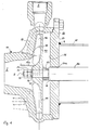
- the centrifugal pump 10 according to the invention shown in Fig. 1 has as Main assemblies a housing 20, a drive shaft 30 and an impeller 40 on.
- the inlet of the centrifugal pump is in Fig. 1 and Fig. 4 with “Z” and the The process is marked with "A”.
- the housing 20 has a first housing section 22 and a second housing section or a housing cover 24, which in a radial division level via suitable connecting means, such as Screws are connected to one another and thereby form a cavity 26 in the inside of which the impeller 40 is rotatably arranged.
- first one Housing part 22 is designed as a molded part and has, in longitudinal cross section considered, the shape of a bowl with a foot. In the foot section is the inlet Z formed, whereas the drain in the radial edge of the shell section is provided.
- the second housing part 24 can be a simple, circular Steel plate. Of course, the second housing part 24 can also be used as Be molded part.
- a connecting pipe 28 On the right outside of the second housing part 24 is a connecting pipe 28 arranged, which extends substantially horizontally and which on attached to the outside of the second housing part 24 via a weld seam S. is.
- the connecting tube 28 In the interior of the connecting tube 28, the one not shown can Electric motor arranged for driving the centrifugal pump 10 according to the invention his.
- the inside of the connecting tube 28 is essentially horizontally extending drive shaft 30 non-rotatably connected to the motor arranged.
- the centrifugal pump according to the invention can also do so be installed so that the drive shaft 30 extends vertically; this is the most most common installation position.
- the drive shaft 30 passes through with it Shaft end 32 shown a passage opening 24a of the second Housing part 24.
- the shaft 30 is provided with a shaft shoulder 34, whose further function will be explained below.
- Impeller 40 rotatably, for example, arranged via a feather key connection.
- the impeller 40 is axially on the shaft 30 firstly by one below pretensioning or adjusting device 50, which is explained in more detail and which is located on the Shaft shoulder 34 supports, and on the other hand by two lock nuts 52, 54 held on the threaded end of the shaft 32 are screwed to the left of the impeller 40.
- a Circlip 56 Between the impeller 40 and the side of the lock nut 54 facing the impeller 40 is a Circlip 56 provided.
- Assembly game which is referred to in Fig. 1 as "gap 2".
- the impeller 40 has a hub 42 which in its Inner circumference with a spring groove 42a (see also FIG. 3) for the rotary driving through the drive shaft 30 is formed.
- a spring groove 42a for the rotary driving through the drive shaft 30 is formed.
- At the right end of the hub 42 extends concentrically to the shaft axis R in one piece on the hub 42 arranged circular disc 44 radially outwards.
- On the one too Forming part forming disc 44 are integrally molded wings 48 which, 3, from the hub 42 radially outwards up to extend the outer circumference of the impeller 40 or the disc 44. All in all are six blades or blades 46 with a uniform pitch of 60 ° intended.
- the elevations 48 have, based on the axis R of Drive shaft 30, a circular segment-shaped cross section and are approximately half the radius of each wing 46.
- the elevations 48 come into contact with them Inner wall portions 22a of the second housing part 22, which together with the Blades 46 radially extending flow channels for the medium to be conveyed or Form fluid.
- the height measured in the axial direction, determines the Drive shaft 30, the elevations 48 between the wings 46 and Inner wall sections 22a of the first housing part 22 resulting gap, which in Fig. 1 is referred to as "gap 1".
- This gap 1 decreases during one Run-in time of the centrifugal pump 10 according to the invention is still a little, since the Work elevations 48 slightly into the inner wall sections 22a and one produce a groove corresponding to its shape, which is not shown in FIGS. 1 and 4 is shown.
- Preload device 50 is provided in order for the elevations 48 to rest securely on the inner wall sections 22a of the first housing section 22 and in particular for reliable contact the run-in phase, in which the elevations 48, as explained above, a groove in the inner wall portions 22a of the first opposite them Incorporate housing part 22 is the one already mentioned above Preload device 50 is provided.
- This biasing device 50 is supported on the one hand on the shaft shoulder 34 and on the other hand on the right front End of the hub 42 of the impeller 40. Due to the elastic formation of the Biasing device 50 is the impeller 40 or the elevations 48 with a defined force against the inner wall portions 22 a of the first housing part 22 pressed.
- the biasing device 50 enables axial Dodge the impeller 40 in the direction of the shaft shoulder 34 at one Penetration of foreign bodies, the size of which corresponds to the size of the disk 44 the wings 46 and the inner wall portions 22a of the first housing part 22 formed flow channel exceeds. After passage of this foreign body the impeller 40 is returned to its initial position by the pretensioner 50 pushed back.
- FIG. 4 shows a further embodiment of the centrifugal pump according to the invention 10, which are essentially different from the embodiment shown in FIG. 1 differs in that the biasing device 50 between the Locknuts 52, 54 and the left end of the hub 42 of the Impeller 40 is arranged.
- the impeller 40 is thus on the shaft shoulder 34 on.
- This state can be seen as a centrifugal pump 10 with "switched off" Biasing device 50 are referred to, whereas the one shown in FIG. 1 Centrifugal pump 10, the biasing device 50 is "turned on”.
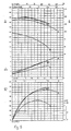
- FIG. 5 and 6 are characteristic diagrams of various centrifugal pumps.
- the diagram contains the delivery head H in m and the power requirement P in kW above the delivery flow Q in m 3 / h for various centrifugal pumps, whereas the lower diagram shows the efficiency ETA in% over the delivery flow Q in m 3 / min.
- the letter "A" in the upper and lower diagram refers to a known centrifugal pump with a closed impeller.
- the letter “B” denotes a known centrifugal pump with a known free flow impeller.
- the efficiency of the centrifugal pump with a closed impeller is greater than the efficiency of the centrifugal pump with a free-flow impeller.
- the letters "C” and “D” indicate a centrifugal pump 10 according to the invention with an impeller 40, as shown in FIGS. 1 to 4.
- the centrifugal pump 10 according to the invention has approximately the same efficiency or, in the case of higher flow rates, a greater efficiency than a centrifugal pump with a closed impeller (line A) or a centrifugal pump with a known free-flow impeller (line B).
- line A closed impeller
- B free-flow impeller
- FIG. 6 are a known centrifugal pump with the letter “A” known free flow bike marked.
- the letters “B” and “C” denote a centrifugal pump 10 according to the invention, the letter “B” the Centrifugal pump 10 according to the invention according to FIG. 4 and the letter “C” die Centrifugal pump 10 according to the invention shown in FIG. 1.
- FIG. 6 is immediately apparent is the efficiency of the invention Centrifugal pump 10 according to FIG. 1 significantly higher than the efficiency of known centrifugal pump with a known free flow impeller and the inventive Centrifugal pump 10 according to FIG. 4. But it can also be seen that the Centrifugal pump 10 according to FIG. 4 is still a satisfactory one Efficiency delivers.
Landscapes
- Engineering & Computer Science (AREA)
- Mechanical Engineering (AREA)
- General Engineering & Computer Science (AREA)
- Physics & Mathematics (AREA)
- Fluid Mechanics (AREA)
- Structures Of Non-Positive Displacement Pumps (AREA)
Abstract
Description
- Fig. 1
- ein Querschnitt durch ein erstes Ausführungsbeispiel einer erfindungsgemäßen Kreiselpumpe;
- Fig. 2
- eine verkleinerte Querschnittsansicht eines in der Kreiselpumpe gemäß Fig. 1 verwendeten erfindungsgemäßen Laufrades;
- Fig. 3
- eine Draufsicht auf das in Fig. 2 gezeigte Laufrad in Richtung X in Fig. 2;
- Fig. 4
- eine Querschnittsansicht eines zweiten Ausführungsbeispiels der erfindungsgemäßen Kreiselpumpe; und
- Fig. 5,6
- Kennliniendiagramme für verschiedene Kreiselpumpen.
Claims (19)
- Kreiselpumpe, mit einem Gehäuse (20) und einem Laufrad (40), das auf einer in dem Gehäuse (20) drehbar gelagerten Antriebswelle (30) drehfest angebracht ist und das eine konzentrisch zu der Antriebswelle (30) angeordnete Scheibe (44) aufweist, auf der in Achsrichtung der Antriebswelle (30) weisende, radial verlaufende Flügel (46) vorgesehen sind, die zusammen mit den den Flügeln (46) der Scheibe (44) gegenüberliegenden Innenwandabschnitten (22a) des Gehäuses (20) Strömungskanäle für das zu pumpende Fluid bilden, dadurch gekennzeichnet, daß an den radial verlaufenden Randkanten (46a) von vorzugsweise drei Flügeln (46) jeweils mindestens eine Erhebung (48) vorgesehen ist, die in Kontakt mit den den Flügeln (46) des Laufrads (40) gegenüberliegenden Innenwandabschnitten (22a) des Gehäuses (20) bringbar sind.
- Kreiselpumpe nach Anspruch 1,
dadurch gekennzeichnet, daß die Erhebungen (48) einstückig an den Flügeln (46) angeformt sind. - Kreiselpumpe nach Anspruch 1 oder 2,
dadurch gekennzeichnet, daß die Erhebungen (48) in einem Längsschnitt parallel zur Achse (R) der Antriebswelle (30) einen kreissegmentförmigen Querschnitt besitzen. - Kreiselpumpe nach einem der Ansprüche 1 bis 3,
dadurch gekennzeichnet, daß die Erhebungen (48) jeweils in etwa im Bereich des halben Radius eines Flügels (46) angeordnet sind. - Kreiselpumpe nach einem der Ansprüche 1 bis 4,
dadurch gekennzeichnet, daß das Montagespiel des Laufrades (40) auf der Antriebswelle (30) kleiner ist als die Höhe der Erhebungen, gemessen in Achsrichtung der Antriebswelle (30). - Kreiselpumpe nach einem der Ansprüche 1 bis 5,
dadurch gekennzeichnet, daß die Erhebungen (48) auf einem zur Achse (R) der Antriebswelle (30) konzentrischen Kreis mit einer gleichmäßigen Teilung, insbesondere von 120° auf den Flügeln (46) angeordnet sind. - Kreiselpumpe nach einem der Ansprüche 1 bis 6, bei dem Gehäuse (20) ein Gußformteil ist,
dadurch gekennzeichnet, daß zumindest die den Flügeln (46) gegenüberliegenden Innenwandabschnitte (22a) des Gehäuses (20) unbearbeitet sind. - Kreiselpumpe nach einem der Ansprüche 1 bis 7,
dadurch gekennzeichnet, daß eine Verstelleinrichtung (50) vorgesehen ist, mittels der die Erhebungen (48) in Anlage mit den den Flügeln (46) gegenüberliegenden Innenwandabschnitten (22a) des Gehäuses (20) drängbar sind. - Kreiselpumpe nach Anspruch 8,
dadurch gekennzeichnet, daß die Verstelleinrichtung (50) auf der Antriebswelle (30) auf der den Flügeln (46) abgewandten Seite der Scheibe (44) angeordnet ist. - Kreiselpumpe nach Anspruch 8,
dadurch gekennzeichnet, daß die Verstelleinrichtung (50) auf der Antriebswelle (30) auf der den Flügeln (46) zugewandten Seite der Scheibe (44) angeordnet ist. - Kreiselpumpe nach einem der Ansprüche 8 bis 10,
dadurch gekennzeichnet, daß die Verstelleinrichtung (50) federelastisch ausgebildet ist. - Kreiselpumpe nach Anspruch 11,
dadurch gekennzeichnet, daß die Verstelleinrichtung durch ein metallisches Federelement, insbesondere eine Schraubendruckfeder (50) gebildet ist. - Kreiselpumpe nach Anspruch 11,
dadurch gekennzeichnet, daß die Verstelleinrichtung durch ein Ringelement (50) aus einem Elastomer gebildet ist. - Laufrad für eine Kreiselpumpe, insbesondere für eine Kreiselpumpe nach einem der Ansprüche 1 bis 13, mit einer auf einer Antriebswelle (30) drehfest und konzentrisch zur Achse (R) der Antriebswelle (30) anordenbaren Scheibe (44), auf deren einen Seite Flügel (46) angeordnet sind, die Teile von Strömungskanälen für das zu pumpende Medium bilden,
dadurch gekennzeichnet, daß an den radial verlaufenden Randkanten (46a) von vorzugsweise drei Flügeln (46) jeweils mindestens eine Erhebung (48) angeordnet ist. - Laufrad nach Anspruch 14,
dadurch gekennzeichnet, daß die Erhebungen (48) einstückig an den Flügeln (46) angeformt sind. - Laufrad nach Anspruch 14 oder 15,
dadurch gekennzeichnet, daß die Erhebungen (48) in einem Längsschnitt parallel zur Rotationsachse der Scheibe (44) einen kreisegmentförmigen Querschnitt besitzen. - Laufrad nach einem der Ansprüche 14 bis 16,
dadurch gekennzeichnet, daß die Erhebungen (48) jeweils in etwa im Bereich des halben Radius eines Flügels (46) angeordnet sind. - Laufrad nach einem der Ansprüche 14 bis 17,
dadurch gekennzeichnet, daß die Erhebungen (48) auf einem zur Rotationsachse der Scheibe (44) konzentrischen Kreis mit einer gleichmäßigen Teilung, insbesondere von 120° auf den Flügeln (46) angeordnet sind. - Laufrad nach einem der Ansprüche 14 bis 18,
dadurch gekennzeichnet, daß das Laufrad (40) ein Freistromrad ist.
Applications Claiming Priority (2)
| Application Number | Priority Date | Filing Date | Title |
|---|---|---|---|
| DE10012181 | 2000-03-13 | ||
| DE10012181A DE10012181C2 (de) | 2000-03-13 | 2000-03-13 | Kreiselpumpe mit Noppen-Laufrad und Noppen-Laufrad hierfür |
Publications (2)
| Publication Number | Publication Date |
|---|---|
| EP1134426A2 true EP1134426A2 (de) | 2001-09-19 |
| EP1134426A3 EP1134426A3 (de) | 2002-09-04 |
Family
ID=7634543
Family Applications (1)
| Application Number | Title | Priority Date | Filing Date |
|---|---|---|---|
| EP01105141A Withdrawn EP1134426A3 (de) | 2000-03-13 | 2001-03-02 | Kreiselpumplaufrad |
Country Status (3)
| Country | Link |
|---|---|
| US (1) | US6551058B2 (de) |
| EP (1) | EP1134426A3 (de) |
| DE (1) | DE10012181C2 (de) |
Cited By (3)
| Publication number | Priority date | Publication date | Assignee | Title |
|---|---|---|---|---|
| DE102010005936A1 (de) * | 2010-01-26 | 2011-07-28 | LICOS Trucktec GmbH, 88677 | Vorrichtung für eine Pumpe sowie Wasserpumpe |
| CN103711710A (zh) * | 2013-12-10 | 2014-04-09 | 中国航空工业集团公司金城南京机电液压工程研究中心 | 一种航空直流电动泵间隙调整方法 |
| CN112761962A (zh) * | 2020-12-31 | 2021-05-07 | 合肥华升泵阀股份有限公司 | 一种具有破碎功能螺旋叶轮及带有该叶轮的离心泵 |
Families Citing this family (21)
| Publication number | Priority date | Publication date | Assignee | Title |
|---|---|---|---|---|
| DE102004005224A1 (de) * | 2004-02-03 | 2005-08-18 | Robert Bosch Gmbh | Förderaggregat |
| SE527964C2 (sv) | 2005-07-01 | 2006-07-25 | Itt Mfg Enterprises Inc | Pump för att pumpa förorenad vätska inkluderande fast material |
| US7371045B2 (en) * | 2005-10-19 | 2008-05-13 | Shurflo, Llc | Pump apparatus and method |
| ATE385290T1 (de) * | 2005-12-21 | 2008-02-15 | Grundfos Management As | Laufrad für ein pumpenaggregat und zugehöriges pumpenaggregat |
| US20090246039A1 (en) * | 2006-01-09 | 2009-10-01 | Grundfos Pumps Corporation | Carrier assembly for a pump |
| CN100404874C (zh) * | 2006-01-21 | 2008-07-23 | 阳江市新力工业有限公司 | 一种冲压焊接食品泵 |
| SE530785C2 (sv) * | 2006-01-23 | 2008-09-09 | Itt Mfg Enterprises Inc | Pump för pumpning av förorenad vätska innefattande fast material |
| US9162019B2 (en) | 2006-04-26 | 2015-10-20 | The Cleveland Clinic Foundation | Two-stage rotodynamic blood pump |
| US7704054B2 (en) * | 2006-04-26 | 2010-04-27 | The Cleveland Clinic Foundation | Two-stage rotodynamic blood pump |
| US8210829B2 (en) * | 2006-04-26 | 2012-07-03 | The Cleveland Clinic Foundation | Two-stage rotodynamic blood pump with axially movable rotor assembly for adjusting hydraulic performance characteristics |
| US8172523B2 (en) * | 2006-10-10 | 2012-05-08 | Grudfos Pumps Corporation | Multistage pump assembly having removable cartridge |
| US7946810B2 (en) * | 2006-10-10 | 2011-05-24 | Grundfos Pumps Corporation | Multistage pump assembly |
| US7958796B2 (en) * | 2008-11-12 | 2011-06-14 | Hiwin Technologies Corp. | Screw-driven fan device |
| US20100284831A1 (en) * | 2009-05-06 | 2010-11-11 | Grundfos Pumps Corporation | Adaptors for multistage pump assemblies |
| JP5705945B1 (ja) * | 2013-10-28 | 2015-04-22 | ミネベア株式会社 | 遠心式ファン |
| US10077777B2 (en) | 2014-05-09 | 2018-09-18 | The Cleveland Clinic Foundation | Artificial heart system implementing suction recognition and avoidance methods |
| JP6064179B2 (ja) * | 2014-06-11 | 2017-01-25 | パナソニックIpマネジメント株式会社 | 温度調和ユニット、温度調和システムおよび温度調和ユニットを備えた車両 |
| DE102015119095B4 (de) * | 2015-11-06 | 2019-03-21 | Pierburg Gmbh | Kühlmittelpumpe für eine Verbrennungskraftmaschine |
| CN110319022B (zh) * | 2019-06-06 | 2020-08-25 | 浙江理工大学 | 离心泵前后盖板间隙可调节的实验测试装置 |
| EP4056852A1 (de) * | 2021-03-09 | 2022-09-14 | Metso Outotec Sweden AB | Schlammpumpe |
| CN115704394A (zh) * | 2021-08-06 | 2023-02-17 | 华为数字能源技术有限公司 | 离心泵 |
Family Cites Families (10)
| Publication number | Priority date | Publication date | Assignee | Title |
|---|---|---|---|---|
| CA503332A (en) * | 1954-05-25 | Andermatt Carl | Centrifugal pump | |
| FR893205A (fr) * | 1942-12-18 | 1944-06-02 | Perfectionnements aux turbo-machines telles que les compresseurs et les pompes centrifuges | |
| US3711218A (en) * | 1971-01-11 | 1973-01-16 | Dorr Oliver Inc | Centrifugal pump with open type impeller |
| US3771927A (en) * | 1972-03-15 | 1973-11-13 | Purex Corp | Impeller running clearance adjustment device |
| US4375937A (en) * | 1981-01-28 | 1983-03-08 | Ingersoll-Rand Company | Roto-dynamic pump with a backflow recirculator |
| DD160237A3 (de) * | 1981-06-19 | 1983-05-18 | Artur Gradewald | Einrichtung an dickstoffkreiselpumpen |
| US4421456A (en) * | 1982-03-15 | 1983-12-20 | C T Manufacturing, Inc. | Centrifugal pump assembly |
| DE4415566C2 (de) * | 1994-05-03 | 1999-02-18 | Sero Pumpenfabrik Gmbh | Seitenkanalpumpe |
| US5800120A (en) * | 1995-11-07 | 1998-09-01 | A. W. Chesterton Co. | Pump impeller with adjustable blades |
| US5951244A (en) * | 1998-01-27 | 1999-09-14 | Knight, Sr.; Michael J. | Impeller clearance adjustment system |
-
2000
- 2000-03-13 DE DE10012181A patent/DE10012181C2/de not_active Expired - Fee Related
-
2001
- 2001-03-02 EP EP01105141A patent/EP1134426A3/de not_active Withdrawn
- 2001-03-12 US US09/803,841 patent/US6551058B2/en not_active Expired - Fee Related
Cited By (4)
| Publication number | Priority date | Publication date | Assignee | Title |
|---|---|---|---|---|
| DE102010005936A1 (de) * | 2010-01-26 | 2011-07-28 | LICOS Trucktec GmbH, 88677 | Vorrichtung für eine Pumpe sowie Wasserpumpe |
| CN103711710A (zh) * | 2013-12-10 | 2014-04-09 | 中国航空工业集团公司金城南京机电液压工程研究中心 | 一种航空直流电动泵间隙调整方法 |
| CN103711710B (zh) * | 2013-12-10 | 2016-01-20 | 中国航空工业集团公司金城南京机电液压工程研究中心 | 一种航空直流电动泵间隙调整方法 |
| CN112761962A (zh) * | 2020-12-31 | 2021-05-07 | 合肥华升泵阀股份有限公司 | 一种具有破碎功能螺旋叶轮及带有该叶轮的离心泵 |
Also Published As
| Publication number | Publication date |
|---|---|
| US20010031202A1 (en) | 2001-10-18 |
| US6551058B2 (en) | 2003-04-22 |
| DE10012181C2 (de) | 2002-05-16 |
| DE10012181A1 (de) | 2001-09-27 |
| EP1134426A3 (de) | 2002-09-04 |
Similar Documents
| Publication | Publication Date | Title |
|---|---|---|
| DE10012181C2 (de) | Kreiselpumpe mit Noppen-Laufrad und Noppen-Laufrad hierfür | |
| DE3327453C2 (de) | ||
| DE69524629T2 (de) | Drosseldurchführung für dichtungshohlraum | |
| EP0640183B1 (de) | Hydrostatische maschine mit leckölabführung | |
| DE19613833A1 (de) | Innenzahnradmaschine, insbesondere Innenzahnradpumpe | |
| DE2253852A1 (de) | Zentrifugalpumpe | |
| DE2653630C2 (de) | Vorrichtung zum Pumpen von Fluiden | |
| EP2233747A1 (de) | Mehrstufiges Kreiselpumpenaggregat | |
| EP1705375B1 (de) | Schlauchpumpe | |
| DE1453730A1 (de) | Radialpumpe | |
| DE1813676A1 (de) | Anordnung in Pumpen | |
| DE60102885T2 (de) | Verschleissbeständige Kraftstoffpumpe | |
| DE1653921C3 (de) | Rotationskolbenpumpe | |
| DE2135268B2 (de) | Hydrodynamische Bremse | |
| DE10247668A1 (de) | Vakuumpumpe | |
| DE3444392C2 (de) | ||
| DE19533151A1 (de) | Leitradnabe mit Freilauf | |
| DE102006049663A1 (de) | Schraubenspindelpumpe mit Scheibenpumpen-Axiallager | |
| DE2626875A1 (de) | Wasserpumpe fuer wassergekuehlte brennkraftmaschinen | |
| DE3045192C2 (de) | Zahnradpumpe | |
| EP4108934A1 (de) | Anordnung umfassend ein laufrad und einen schneidkopf für mit feststoff belastete flüssigkeit einer pumpe | |
| DE3108214A1 (de) | "kraftstoff-foerderpumpe mit zwei hintereinander geschalteten pumpenstufen" | |
| DE3438480A1 (de) | Mehrstufige kreiselpumpe mit geschlossenem laufradgehaeuse | |
| DE3113944C2 (de) | ||
| EP1053402A1 (de) | Kreiselpumpenlaufrad radialer bauart |
Legal Events
| Date | Code | Title | Description |
|---|---|---|---|
| PUAI | Public reference made under article 153(3) epc to a published international application that has entered the european phase |
Free format text: ORIGINAL CODE: 0009012 |
|
| AK | Designated contracting states |
Kind code of ref document: A2 Designated state(s): AT BE CH CY DE DK ES FI FR GB GR IE IT LI LU MC NL PT SE TR |
|
| AX | Request for extension of the european patent |
Free format text: AL;LT;LV;MK;RO;SI |
|
| PUAL | Search report despatched |
Free format text: ORIGINAL CODE: 0009013 |
|
| AK | Designated contracting states |
Kind code of ref document: A3 Designated state(s): AT BE CH CY DE DK ES FI FR GB GR IE IT LI LU MC NL PT SE TR |
|
| AX | Request for extension of the european patent |
Free format text: AL;LT;LV;MK;RO;SI |
|
| 17P | Request for examination filed |
Effective date: 20030304 |
|
| AKX | Designation fees paid |
Designated state(s): AT BE CH CY DE DK ES FI FR GB GR IE IT LI LU MC NL PT SE TR |
|
| STAA | Information on the status of an ep patent application or granted ep patent |
Free format text: STATUS: THE APPLICATION IS DEEMED TO BE WITHDRAWN |
|
| 18D | Application deemed to be withdrawn |
Effective date: 20040331 |