EP1134450A2 - Amortisseur à air utilisé pour la boite à gants d'une automobile - Google Patents
Amortisseur à air utilisé pour la boite à gants d'une automobile Download PDFInfo
- Publication number
- EP1134450A2 EP1134450A2 EP01302456A EP01302456A EP1134450A2 EP 1134450 A2 EP1134450 A2 EP 1134450A2 EP 01302456 A EP01302456 A EP 01302456A EP 01302456 A EP01302456 A EP 01302456A EP 1134450 A2 EP1134450 A2 EP 1134450A2
- Authority
- EP
- European Patent Office
- Prior art keywords
- piston
- cylinder
- string
- air damper
- guide cap
- Prior art date
- Legal status (The legal status is an assumption and is not a legal conclusion. Google has not performed a legal analysis and makes no representation as to the accuracy of the status listed.)
- Granted
Links
- 230000006835 compression Effects 0.000 claims abstract description 30
- 238000007906 compression Methods 0.000 claims abstract description 30
- 230000001105 regulatory effect Effects 0.000 description 5
- 230000004048 modification Effects 0.000 description 4
- 238000012986 modification Methods 0.000 description 4
- 230000000694 effects Effects 0.000 description 3
- 238000005192 partition Methods 0.000 description 2
- 238000010420 art technique Methods 0.000 description 1
- 230000006866 deterioration Effects 0.000 description 1
- 238000006073 displacement reaction Methods 0.000 description 1
- 230000000717 retained effect Effects 0.000 description 1
- 238000006467 substitution reaction Methods 0.000 description 1
- 230000008961 swelling Effects 0.000 description 1
Images



Classifications
-
- F—MECHANICAL ENGINEERING; LIGHTING; HEATING; WEAPONS; BLASTING
- F16—ENGINEERING ELEMENTS AND UNITS; GENERAL MEASURES FOR PRODUCING AND MAINTAINING EFFECTIVE FUNCTIONING OF MACHINES OR INSTALLATIONS; THERMAL INSULATION IN GENERAL
- F16F—SPRINGS; SHOCK-ABSORBERS; MEANS FOR DAMPING VIBRATION
- F16F9/00—Springs, vibration-dampers, shock-absorbers, or similarly-constructed movement-dampers using a fluid or the equivalent as damping medium
- F16F9/32—Details
- F16F9/58—Stroke limiting stops, e.g. arranged on the piston rod outside the cylinder
-
- F—MECHANICAL ENGINEERING; LIGHTING; HEATING; WEAPONS; BLASTING
- F16—ENGINEERING ELEMENTS AND UNITS; GENERAL MEASURES FOR PRODUCING AND MAINTAINING EFFECTIVE FUNCTIONING OF MACHINES OR INSTALLATIONS; THERMAL INSULATION IN GENERAL
- F16F—SPRINGS; SHOCK-ABSORBERS; MEANS FOR DAMPING VIBRATION
- F16F9/00—Springs, vibration-dampers, shock-absorbers, or similarly-constructed movement-dampers using a fluid or the equivalent as damping medium
- F16F9/02—Springs, vibration-dampers, shock-absorbers, or similarly-constructed movement-dampers using a fluid or the equivalent as damping medium using gas only or vacuum
-
- F—MECHANICAL ENGINEERING; LIGHTING; HEATING; WEAPONS; BLASTING
- F16—ENGINEERING ELEMENTS AND UNITS; GENERAL MEASURES FOR PRODUCING AND MAINTAINING EFFECTIVE FUNCTIONING OF MACHINES OR INSTALLATIONS; THERMAL INSULATION IN GENERAL
- F16F—SPRINGS; SHOCK-ABSORBERS; MEANS FOR DAMPING VIBRATION
- F16F9/00—Springs, vibration-dampers, shock-absorbers, or similarly-constructed movement-dampers using a fluid or the equivalent as damping medium
- F16F9/32—Details
- F16F9/3207—Constructional features
- F16F9/3214—Constructional features of pistons
Definitions
- the present invention generally relates to an air damper, and more specifically, to an improved structure of a cylindrical air damper installed in, for example, the glove box of an automobile.
- a conventional cylindrical air damper fixed to the glove box of an automobile is disclosed in, for example, Japanese Utility Model Registration No. 2557064.
- This type of air damper is used to dampen the abrupt opening motion of the glove box, or to prevent unpleasant noise due to sudden opening.
- the air damper allows the glove box to open slowly about the pivoting axis against the gravitational force.
- the conventional air damper comprises a cylinder with openings at both ends, and a piston moving in the cylinder.
- a string is coupled with the piston, and it extends out of the cylinder from the remote end.
- a valve is attached to the base or the close end to control the quantity of the air passing through the cylinder.
- a guide cap is attached to the remote end of the cylinder to guide the string.
- a compression coil spring is inserted between the guide cap and the piston.
- the air damper is fixed to, for example, the instrument panel, which is the back wall of the glove box.
- the string extending from the guide cap of the cylinder is coupled to the glove box.
- the string is pulled out of the cylinder, and the piston coupled to the spring moves inside the cylinder, while compressing the coil spring. Consequently, the air flows into the cylinder via the valve, which give the damper effect to the cylinder.
- the glove box slowly open toward the opening position.
- the full-open position of the glove box using an air damper has to be regulated.
- a guide groove is formed in the instrument panel itself or the cover sheet furnished to an appropriate place on the instrument panel, as disclosed in Japanese Utility Model No. 2587728.
- a stopper pin is provided to the side face of the glove box in such a manner that the stopper pin moves along the guide groove as the glove box is opened or closed. If the glove box slowly opens by its own weight, the stopper pin moves in the groove, and comes to the end of the groove. The abutment between the stopper pin and the end of the groove regulates the full-open position of the glove box.
- the major objective of the invention is to provide an improved structure of an air damper used in the glove box of an automobile.
- the improved air damper is capable of functioning as a means for regulating the full-open position of the glove box, without causing the compression coil spring of the air damper to be damaged or deteriorated.
- an air damper comprises a cylinder with a first open end and a second end, a guide cap covering the first open end, and a piston movable in the cylinder.
- a compression coil spring is inserted in the cylinder between the piston and the guide cap. The coil spring forces the piston toward the second end of the cylinder in the free state.
- a string is coupled with the piston, and it extends out of the cylinder.
- a stopper means is positioned between the guide cap and the piston in order to stop the piston before the compression coil spring is fully compressed when the string is pulled to cause the piston to move toward the guide cap.
- the stopper means is located inside the compression coil spring. This arrangement allows the air damper to be kept compact, without requiring an extra space for accommodating the coil spring.
- the stopper means is connected to the guide cap, or alternatively, the stopper means is connected to the piston.
- the piston has a hook piece facing the guide cap.
- the hook piece is threaded with the string in such a manner that at least one end of the string is taken out of the cylinder via the guide cap.
- the string is doubled at the hook piece, and movable through the hook piece.
- the one end of the string is coupled with the side edge of the glove box. If the glove box is opened, the string is pulled out of the cylinder, which causes the piston to move toward the guide cap. Since there is a stopper means between the piston and the guide cap, the piston strikes the stopper means before the compression coil spring is fully compressed. This arrangement can prevent the coil spring from being deteriorated due to excessive load by the weight of the glove box. Simultaneously, the stopper means reliably defines the full-open position of the glove box, because the glove box is retained in a stable manner at a position determined by the length of the stopper means
- Fig. 1 illustrates an example of the air damper according to the preferred embodiment of the invention in an exploded view.
- the air damper comprises a cylinder 1 having a first open end 13 (Fig. 4) and a second open end 3, and a piston 2 accommodated in the cylinder so as to be movable along the axis of the cylinder 1.
- the first opening 13 functions as a leading port
- the second opening 3 functions as an air hole 3.
- a string 8 is coupled to the piston 2 in order to transfer a damper effect generated by the motion of the piston to the glove box (not shown).
- the string 8 may be a lace, a code, a belt, or the like.
- a guide cap 6 is provided to the leading port to guide the string 8 out of the cylinder 1.
- An end cap 5 is provided to the air hole 3 with an air valve 4 between them.
- the air damper also has a compression coil spring 7, which is inserted in the cylinder 1 between the piston 2 and the guide cap 6. In the free state, the spring 7 forces the piston 2 toward the end cap 5.
- the cylinder 1 has an L-shaped hook 9 on its outer face near the leading port in order to hook one end 8a of the string 8.
- the piston 2 has O-rings 10 around the outer face, and a hook piece 11 threaded with the string 8.
- the string 8 is doubled at the hook piece 11 in a movable manner, and extends in the axial direction in the cylinder 1.
- one end 8a of the string 8 is hooked at the L-shaped hook 9, and the other end 8b is coupled to a side edge of the glove box (not shown). In this example, the ends 8a and 8b are looped.
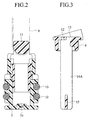
- Fig. 2 illustrated in a cross-sectional view the piston 2, to which a string 8 (illustrated by a ghost line) is coupled.
- the O-rings 10 are fit into the threads formed in the outer face of the piston 2.
- the hook piece 11 has a swelling wall, which functions as a reel to allow the string 8 to be pulled in both directions.
- the piston 2 has an orifice 2a at the bottom face.
- Fig. 3 illustrates in a cross-sectional view the guide cap 6 provided to the leading port of the cylinder 1.
- the guide cap 6 has a pair of stopper plates 14A, between which a partition 15 is inserted.
- the guide cap 6 has a hole 12 for receiving one end 8a of the string 8, and a guide hole 13 for allowing the other end 8b of the string 8 to be pulled out of the cylinder 1. Both ends 8a and 8b of the string 8 doubled at the hook piece 11 are separated by the partition 15 and inserted in the holes 12 and 13, respectively.
- the stopper plates 14A extend inside the compression coil spring 7 toward the hook piece 11 of the piston 2. This arrangement eliminates necessity for an extra space, and prevents the cylinder 1 from becoming large.
- the string 8 is threaded in the hook piece 11 of the piston 2, and pulled in double inside the compression coil spring 7. Then, the piston 2 and the compression coil spring 7 are inserted into the cylinder 1 from the leading port.
- the hole 12 of the guide cap 6 is threaded with one end 8a of the spring 8, while the guide hole 13 of the guide cap 6 is threaded with the other end 8b of the spring 8, before the guide cap 6 is fixed to the cylinder 1.
- the guide cap 6 is then attached to the cylinder 1, and one end 8a of the spring 8 is hooked at the L-shaped hook 9. In this manner, the air damper is assembled into a single unit, as shown in Fig. 4.
- the stopper plates 14A of the guide cap 6 project into the cylinder 1 inside the compression coil spring 7.
- the cylinder 1 of the air damper When installing the air damper in the glove box of an automobile, the cylinder 1 of the air damper is secured to the instrument panel (not shown) or the cover (not shown) attached to an appropriate place on the instrument panel. Then, the looped end 8b of the spring 8 extending from the guide cap 8 is pulled out of the cylinder 1, and coupled to the side edge of the globe box.
- the spring 8 In the preferred embodiment, the spring 8 is doubled in the cylinder, and therefore, the amount of pull of the spring 8 is twice as much as the displacement of the piston 2.
- the glove box pivots about its axis and starts opening under the gravitational force.
- the spring 8 is pulled out of the cylinder 1, and the piston 2 moves toward the guide cap 6, while compressing the compression coil spring 7.
- the air compressed in the cylinder starts flowing through the orifice 2a of the piston 2, and the flow resistance of the air flowing through the orifice 2a generates a damper effect, which prevents the glove box from abruptly opening. As a result, the gentle opening of the glove box is guaranteed.
- the hook piece 11 of the piston 2 hits the tips of the stopper plates 14A projecting from the guide cap 6 before the compression coil spring 7 is completely compressed, as illustrated in Fig. 5.
- the stopper plates 14A prevent the piston 2 from further advancing toward the guide cap 6.
- the full-open position of the glove box is defined in a stable manner by the abutment between the piston 2 and the stopper plates 14A without causing undesirable fluctuation in the full-open position. This arrangement does not require an additional separate means for regulating the full-open position.
- the compression coil spring 7 is not fully compressed even if the glove box is held at the full-open position, the spring force will not be weakened. In addition, the air damper is protected from being damaged or broken due to the full compression of the coil spring.
- the piston 2 If returning the glove box to the close position, the piston 2 is pushed back toward the end cap 5 by the restoring force of the compression coil spring 7, accompanying the string 8. During the return motion of the piston 2, the valve 4 is opened, and the air stored between the piston 2 and the end cap 4 is escaped via the valve 4 into the atmosphere so as to guarantee the smooth return of the piston 2.
- Fig. 6 illustrates a modification of the air damper, in which the stopper plates 14B are furnished to the piston 2 on both sides of the hook piece 11.
- the stopper plates 14B project toward the guide cap 6 inside the compression coil spring 7.
- the air damper can be kept compact because the stopper plates 14B are accommodated inside the coil spring 7.
- the tips of the stopper plates 14B projecting from the piston 2 hit the guide cap 6 before the compression coil spring 7 is fully compressed.
- the abutment between the stopper plates 14B and the guide cap 6 prevents the piston 2 from further advancing toward the guide cap 6, and defines the full-open position of the glove box in a stable manner. Since the compression coil spring 7 is protected from an excessive amount of load, it will not be weakened even if the glove box is held at the full-open position.
- the air damper itself is also protected from being damaged or broken at brittle portions.
- the full-open position of the glove box is easily adjusted simply by setting the length of the stopper plates 14A or 14B to an appropriate value.
- the air damper of the present invention guarantees gentle opening of the glove box, and at the same time, it functions as a means for regulating the full-open position of the glove box.
- the full-open position of the glove box can be easily adjusted simply by changing the length of the stopper plates.
- the air damper works in a reliable manner without being damaged or broken due to deterioration of the coil spring.
Landscapes
- Engineering & Computer Science (AREA)
- General Engineering & Computer Science (AREA)
- Mechanical Engineering (AREA)
- Vehicle Step Arrangements And Article Storage (AREA)
- Fluid-Damping Devices (AREA)
- Closing And Opening Devices For Wings, And Checks For Wings (AREA)
Applications Claiming Priority (2)
| Application Number | Priority Date | Filing Date | Title |
|---|---|---|---|
| JP2000076112A JP3768061B2 (ja) | 2000-03-17 | 2000-03-17 | エアダンパー |
| JP2000076112 | 2000-03-17 |
Publications (3)
| Publication Number | Publication Date |
|---|---|
| EP1134450A2 true EP1134450A2 (fr) | 2001-09-19 |
| EP1134450A3 EP1134450A3 (fr) | 2002-04-17 |
| EP1134450B1 EP1134450B1 (fr) | 2004-11-17 |
Family
ID=18593898
Family Applications (1)
| Application Number | Title | Priority Date | Filing Date |
|---|---|---|---|
| EP01302456A Expired - Lifetime EP1134450B1 (fr) | 2000-03-17 | 2001-03-16 | Amortisseur à air utilisé pour la boite à gants d'une automobile |
Country Status (5)
| Country | Link |
|---|---|
| US (1) | US6669178B2 (fr) |
| EP (1) | EP1134450B1 (fr) |
| JP (1) | JP3768061B2 (fr) |
| AT (1) | ATE282535T1 (fr) |
| DE (1) | DE60107133T2 (fr) |
Cited By (2)
| Publication number | Priority date | Publication date | Assignee | Title |
|---|---|---|---|---|
| EP1764528A1 (fr) * | 2005-09-14 | 2007-03-21 | Hörauf & Kohler Verwaltungs KG | Amortisseur de mouvement |
| FR2920505A1 (fr) * | 2007-08-31 | 2009-03-06 | Piolax Inc | Dispositif d'amortissement destine a amortir l'operation d'ouverture d'un element pouvant etre ouvert/ferme |
Families Citing this family (14)
| Publication number | Priority date | Publication date | Assignee | Title |
|---|---|---|---|---|
| JP3994042B2 (ja) * | 2002-09-20 | 2007-10-17 | 株式会社パイオラックス | 紐式エアダンパー |
| US7108038B2 (en) * | 2003-02-14 | 2006-09-19 | Hunter Douglas Industries Bv | Cord tensioner |
| KR20050041521A (ko) * | 2003-10-31 | 2005-05-04 | 현대자동차주식회사 | 자동차 글로브 박스의 일체형 에어댐퍼 |
| US20050242256A1 (en) * | 2004-05-03 | 2005-11-03 | Evans Robert S | Glove box hook apparatus |
| KR100565372B1 (ko) * | 2004-06-09 | 2006-03-30 | 현대모비스 주식회사 | 글로브 박스의 댐핑 시스템 |
| JP4668738B2 (ja) | 2005-08-29 | 2011-04-13 | 株式会社パイオラックス | エアダンパ及びその製造方法 |
| JP4636987B2 (ja) * | 2005-10-04 | 2011-02-23 | 株式会社パイオラックス | エアダンパ |
| US7549249B2 (en) * | 2006-09-01 | 2009-06-23 | Richard Tamian | Reverse action, spring-loaded fishing tackle device |
| JP2011127648A (ja) * | 2009-12-16 | 2011-06-30 | Nifco Inc | ダンパー装置 |
| DE102013212773B4 (de) * | 2013-06-28 | 2023-06-22 | Bayerische Motoren Werke Aktiengesellschaft | Handschuhfach |
| US10221909B2 (en) | 2014-01-31 | 2019-03-05 | Piolax, Inc. | Damper device |
| WO2023182215A1 (fr) * | 2022-03-24 | 2023-09-28 | 株式会社パイオラックス | Dispositif amortisseur |
| KR102684046B1 (ko) * | 2022-04-04 | 2024-07-12 | 현대모비스 주식회사 | 글로브 박스용 댐퍼 및 이를 포함하는 글로브 박스 |
| JP2025029737A (ja) * | 2023-08-22 | 2025-03-07 | 株式会社パイオラックス | ダンパー装置 |
Citations (2)
| Publication number | Priority date | Publication date | Assignee | Title |
|---|---|---|---|---|
| JP2557064Y2 (ja) | 1992-03-25 | 1997-12-08 | 株式会社パイオラックス | 収納箱等のダンパ−装置の構造 |
| JP2587728Y2 (ja) | 1992-03-02 | 1998-12-24 | 三菱自動車工業株式会社 | ダンパー機能を備える自動車用収納装置 |
Family Cites Families (8)
| Publication number | Priority date | Publication date | Assignee | Title |
|---|---|---|---|---|
| US199716A (en) * | 1878-01-29 | Improvement in stirrup-suspenders for riding-saddles | ||
| GB790647A (en) | 1955-05-11 | 1958-02-12 | Armstrong Patents Co Ltd | Improvements in or relating to telescopic hydraulic shock absorbers |
| FR1372781A (fr) | 1963-10-23 | 1964-09-18 | Stabilus | Perfectionnements aux dispositifs élastiques à gaz à fonctionnement graduel |
| DE2951093A1 (de) | 1979-12-19 | 1981-07-02 | Stabilus Gmbh, 5400 Koblenz | Gasfeder mit einschubsicherung in ausgefahrener position |
| US5845749A (en) | 1995-10-11 | 1998-12-08 | Tmj Properties, L.L.C. | Linear motion absorber with synthetic components |
| US5613665A (en) * | 1995-11-09 | 1997-03-25 | Lund; Ronn A. | Vehicle suspension component |
| JP3321665B2 (ja) * | 1998-11-06 | 2002-09-03 | 株式会社パイオラックス | エアダンパー |
| JP3513650B2 (ja) * | 2000-01-07 | 2004-03-31 | 株式会社パイオラックス | エアダンパー |
-
2000
- 2000-03-17 JP JP2000076112A patent/JP3768061B2/ja not_active Expired - Fee Related
-
2001
- 2001-03-16 US US09/811,292 patent/US6669178B2/en not_active Expired - Fee Related
- 2001-03-16 DE DE60107133T patent/DE60107133T2/de not_active Expired - Lifetime
- 2001-03-16 EP EP01302456A patent/EP1134450B1/fr not_active Expired - Lifetime
- 2001-03-16 AT AT01302456T patent/ATE282535T1/de not_active IP Right Cessation
Patent Citations (2)
| Publication number | Priority date | Publication date | Assignee | Title |
|---|---|---|---|---|
| JP2587728Y2 (ja) | 1992-03-02 | 1998-12-24 | 三菱自動車工業株式会社 | ダンパー機能を備える自動車用収納装置 |
| JP2557064Y2 (ja) | 1992-03-25 | 1997-12-08 | 株式会社パイオラックス | 収納箱等のダンパ−装置の構造 |
Cited By (3)
| Publication number | Priority date | Publication date | Assignee | Title |
|---|---|---|---|---|
| EP1764528A1 (fr) * | 2005-09-14 | 2007-03-21 | Hörauf & Kohler Verwaltungs KG | Amortisseur de mouvement |
| DE102005043785A1 (de) * | 2005-09-14 | 2007-03-22 | Hörauf & Kohler Verwaltungs KG | Bewegungsdämpfer |
| FR2920505A1 (fr) * | 2007-08-31 | 2009-03-06 | Piolax Inc | Dispositif d'amortissement destine a amortir l'operation d'ouverture d'un element pouvant etre ouvert/ferme |
Also Published As
| Publication number | Publication date |
|---|---|
| ATE282535T1 (de) | 2004-12-15 |
| JP2001263399A (ja) | 2001-09-26 |
| DE60107133T2 (de) | 2005-12-29 |
| EP1134450A3 (fr) | 2002-04-17 |
| US6669178B2 (en) | 2003-12-30 |
| DE60107133D1 (de) | 2004-12-23 |
| JP3768061B2 (ja) | 2006-04-19 |
| EP1134450B1 (fr) | 2004-11-17 |
| US20010023800A1 (en) | 2001-09-27 |
Similar Documents
| Publication | Publication Date | Title |
|---|---|---|
| EP1134450A2 (fr) | Amortisseur à air utilisé pour la boite à gants d'une automobile | |
| US10538950B2 (en) | Lid hinge assembly with snubber and counterbalance spring | |
| JP2557064Y2 (ja) | 収納箱等のダンパ−装置の構造 | |
| US6789293B2 (en) | Dampened hinge system for appliance door | |
| US10907389B2 (en) | Slow open and/or slow close hinge assembly and hinge system | |
| US5188334A (en) | Pinch valve assembly with a storage mode | |
| US20100162522A1 (en) | Damper device | |
| US6367785B1 (en) | Air damper | |
| US20020113158A1 (en) | Apparatus for winding sheet-like element | |
| US6209503B1 (en) | Intake duct | |
| EP1739261A1 (fr) | Articulation avec amortisseur | |
| JP4700960B2 (ja) | ドアクローザ | |
| US6269919B1 (en) | Plastic strand damper | |
| JP3681491B2 (ja) | 引き戸クローザ | |
| KR102146428B1 (ko) | 미세 차압조절용 릴리프 댐퍼 | |
| JP4026066B2 (ja) | 建築用開閉体における衝撃緩衝装置 | |
| JPH1061702A (ja) | 開閉用ダンパー | |
| US6240598B1 (en) | Arrangement for controlling an angularly movable member | |
| JP2001238976A (ja) | 消火栓装置 | |
| CA2299929A1 (fr) | Vannes de coupure de moteur | |
| KR102327282B1 (ko) | 슬라이딩 도어용 댐핑장치 | |
| JP3374109B2 (ja) | 扉の自動閉止装置 | |
| JP2001193345A (ja) | 扉の自動閉止装置 | |
| KR900008248Y1 (ko) | 카세트 도어 댐퍼 장치 | |
| JP3252337B2 (ja) | ダンパー装置 |
Legal Events
| Date | Code | Title | Description |
|---|---|---|---|
| PUAI | Public reference made under article 153(3) epc to a published international application that has entered the european phase |
Free format text: ORIGINAL CODE: 0009012 |
|
| AK | Designated contracting states |
Kind code of ref document: A2 Designated state(s): AT BE CH CY DE DK ES FI FR GB GR IE IT LI LU MC NL PT SE TR |
|
| AX | Request for extension of the european patent |
Free format text: AL;LT;LV;MK;RO;SI |
|
| PUAL | Search report despatched |
Free format text: ORIGINAL CODE: 0009013 |
|
| RIC1 | Information provided on ipc code assigned before grant |
Free format text: 7B 60R 7/06 A, 7F 16F 9/02 B, 7F 16F 9/58 B |
|
| AK | Designated contracting states |
Kind code of ref document: A3 Designated state(s): AT BE CH CY DE DK ES FI FR GB GR IE IT LI LU MC NL PT SE TR |
|
| AX | Request for extension of the european patent |
Free format text: AL;LT;LV;MK;RO;SI |
|
| 17P | Request for examination filed |
Effective date: 20020924 |
|
| AKX | Designation fees paid |
Free format text: AT BE CH CY DE DK ES FI FR GB GR IE IT LI LU MC NL PT SE TR |
|
| 17Q | First examination report despatched |
Effective date: 20030825 |
|
| GRAP | Despatch of communication of intention to grant a patent |
Free format text: ORIGINAL CODE: EPIDOSNIGR1 |
|
| GRAS | Grant fee paid |
Free format text: ORIGINAL CODE: EPIDOSNIGR3 |
|
| GRAA | (expected) grant |
Free format text: ORIGINAL CODE: 0009210 |
|
| AK | Designated contracting states |
Kind code of ref document: B1 Designated state(s): AT BE CH CY DE DK ES FI FR GB GR IE IT LI LU MC NL PT SE TR |
|
| PG25 | Lapsed in a contracting state [announced via postgrant information from national office to epo] |
Ref country code: IT Free format text: LAPSE BECAUSE OF FAILURE TO SUBMIT A TRANSLATION OF THE DESCRIPTION OR TO PAY THE FEE WITHIN THE PRESCRIBED TIME-LIMIT;WARNING: LAPSES OF ITALIAN PATENTS WITH EFFECTIVE DATE BEFORE 2007 MAY HAVE OCCURRED AT ANY TIME BEFORE 2007. THE CORRECT EFFECTIVE DATE MAY BE DIFFERENT FROM THE ONE RECORDED. Effective date: 20041117 Ref country code: FR Free format text: LAPSE BECAUSE OF FAILURE TO SUBMIT A TRANSLATION OF THE DESCRIPTION OR TO PAY THE FEE WITHIN THE PRESCRIBED TIME-LIMIT Effective date: 20041117 Ref country code: AT Free format text: LAPSE BECAUSE OF FAILURE TO SUBMIT A TRANSLATION OF THE DESCRIPTION OR TO PAY THE FEE WITHIN THE PRESCRIBED TIME-LIMIT Effective date: 20041117 Ref country code: NL Free format text: LAPSE BECAUSE OF FAILURE TO SUBMIT A TRANSLATION OF THE DESCRIPTION OR TO PAY THE FEE WITHIN THE PRESCRIBED TIME-LIMIT Effective date: 20041117 Ref country code: TR Free format text: LAPSE BECAUSE OF FAILURE TO SUBMIT A TRANSLATION OF THE DESCRIPTION OR TO PAY THE FEE WITHIN THE PRESCRIBED TIME-LIMIT Effective date: 20041117 Ref country code: CH Free format text: LAPSE BECAUSE OF FAILURE TO SUBMIT A TRANSLATION OF THE DESCRIPTION OR TO PAY THE FEE WITHIN THE PRESCRIBED TIME-LIMIT Effective date: 20041117 Ref country code: BE Free format text: LAPSE BECAUSE OF FAILURE TO SUBMIT A TRANSLATION OF THE DESCRIPTION OR TO PAY THE FEE WITHIN THE PRESCRIBED TIME-LIMIT Effective date: 20041117 Ref country code: LI Free format text: LAPSE BECAUSE OF FAILURE TO SUBMIT A TRANSLATION OF THE DESCRIPTION OR TO PAY THE FEE WITHIN THE PRESCRIBED TIME-LIMIT Effective date: 20041117 Ref country code: FI Free format text: LAPSE BECAUSE OF FAILURE TO SUBMIT A TRANSLATION OF THE DESCRIPTION OR TO PAY THE FEE WITHIN THE PRESCRIBED TIME-LIMIT Effective date: 20041117 |
|
| REG | Reference to a national code |
Ref country code: GB Ref legal event code: FG4D |
|
| REG | Reference to a national code |
Ref country code: CH Ref legal event code: EP |
|
| REG | Reference to a national code |
Ref country code: IE Ref legal event code: FG4D |
|
| REF | Corresponds to: |
Ref document number: 60107133 Country of ref document: DE Date of ref document: 20041223 Kind code of ref document: P |
|
| PG25 | Lapsed in a contracting state [announced via postgrant information from national office to epo] |
Ref country code: DK Free format text: LAPSE BECAUSE OF FAILURE TO SUBMIT A TRANSLATION OF THE DESCRIPTION OR TO PAY THE FEE WITHIN THE PRESCRIBED TIME-LIMIT Effective date: 20050217 Ref country code: SE Free format text: LAPSE BECAUSE OF FAILURE TO SUBMIT A TRANSLATION OF THE DESCRIPTION OR TO PAY THE FEE WITHIN THE PRESCRIBED TIME-LIMIT Effective date: 20050217 Ref country code: GR Free format text: LAPSE BECAUSE OF FAILURE TO SUBMIT A TRANSLATION OF THE DESCRIPTION OR TO PAY THE FEE WITHIN THE PRESCRIBED TIME-LIMIT Effective date: 20050217 |
|
| PG25 | Lapsed in a contracting state [announced via postgrant information from national office to epo] |
Ref country code: ES Free format text: LAPSE BECAUSE OF FAILURE TO SUBMIT A TRANSLATION OF THE DESCRIPTION OR TO PAY THE FEE WITHIN THE PRESCRIBED TIME-LIMIT Effective date: 20050228 |
|
| PG25 | Lapsed in a contracting state [announced via postgrant information from national office to epo] |
Ref country code: CY Free format text: LAPSE BECAUSE OF FAILURE TO SUBMIT A TRANSLATION OF THE DESCRIPTION OR TO PAY THE FEE WITHIN THE PRESCRIBED TIME-LIMIT Effective date: 20050316 Ref country code: LU Free format text: LAPSE BECAUSE OF NON-PAYMENT OF DUE FEES Effective date: 20050316 Ref country code: GB Free format text: LAPSE BECAUSE OF NON-PAYMENT OF DUE FEES Effective date: 20050316 Ref country code: IE Free format text: LAPSE BECAUSE OF NON-PAYMENT OF DUE FEES Effective date: 20050316 |
|
| PG25 | Lapsed in a contracting state [announced via postgrant information from national office to epo] |
Ref country code: MC Free format text: LAPSE BECAUSE OF NON-PAYMENT OF DUE FEES Effective date: 20050331 |
|
| NLV1 | Nl: lapsed or annulled due to failure to fulfill the requirements of art. 29p and 29m of the patents act | ||
| REG | Reference to a national code |
Ref country code: CH Ref legal event code: PL |
|
| PLBE | No opposition filed within time limit |
Free format text: ORIGINAL CODE: 0009261 |
|
| STAA | Information on the status of an ep patent application or granted ep patent |
Free format text: STATUS: NO OPPOSITION FILED WITHIN TIME LIMIT |
|
| 26N | No opposition filed |
Effective date: 20050818 |
|
| GBPC | Gb: european patent ceased through non-payment of renewal fee |
Effective date: 20050316 |
|
| REG | Reference to a national code |
Ref country code: IE Ref legal event code: MM4A |
|
| EN | Fr: translation not filed | ||
| PG25 | Lapsed in a contracting state [announced via postgrant information from national office to epo] |
Ref country code: PT Free format text: LAPSE BECAUSE OF NON-PAYMENT OF DUE FEES Effective date: 20050417 |
|
| PGFP | Annual fee paid to national office [announced via postgrant information from national office to epo] |
Ref country code: DE Payment date: 20190305 Year of fee payment: 19 |
|
| REG | Reference to a national code |
Ref country code: DE Ref legal event code: R119 Ref document number: 60107133 Country of ref document: DE |
|
| PG25 | Lapsed in a contracting state [announced via postgrant information from national office to epo] |
Ref country code: DE Free format text: LAPSE BECAUSE OF NON-PAYMENT OF DUE FEES Effective date: 20201001 |