EP1134537A2 - Installation de nettoyage pour l'extraction de la suie - Google Patents
Installation de nettoyage pour l'extraction de la suie Download PDFInfo
- Publication number
- EP1134537A2 EP1134537A2 EP01200244A EP01200244A EP1134537A2 EP 1134537 A2 EP1134537 A2 EP 1134537A2 EP 01200244 A EP01200244 A EP 01200244A EP 01200244 A EP01200244 A EP 01200244A EP 1134537 A2 EP1134537 A2 EP 1134537A2
- Authority
- EP
- European Patent Office
- Prior art keywords
- flow
- air
- flow passage
- processing system
- valve
- Prior art date
- Legal status (The legal status is an assumption and is not a legal conclusion. Google has not performed a legal analysis and makes no representation as to the accuracy of the status listed.)
- Granted
Links
Images


Classifications
-
- F—MECHANICAL ENGINEERING; LIGHTING; HEATING; WEAPONS; BLASTING
- F28—HEAT EXCHANGE IN GENERAL
- F28G—CLEANING OF INTERNAL OR EXTERNAL SURFACES OF HEAT-EXCHANGE OR HEAT-TRANSFER CONDUITS, e.g. WATER TUBES OR BOILERS
- F28G9/00—Cleaning by flushing or washing, e.g. with chemical solvents
-
- B—PERFORMING OPERATIONS; TRANSPORTING
- B08—CLEANING
- B08B—CLEANING IN GENERAL; PREVENTION OF FOULING IN GENERAL
- B08B5/00—Cleaning by methods involving the use of air flow or gas flow
- B08B5/02—Cleaning by the force of jets, e.g. blowing-out cavities
-
- B—PERFORMING OPERATIONS; TRANSPORTING
- B08—CLEANING
- B08B—CLEANING IN GENERAL; PREVENTION OF FOULING IN GENERAL
- B08B9/00—Cleaning hollow articles by methods or apparatus specially adapted thereto
-
- B—PERFORMING OPERATIONS; TRANSPORTING
- B08—CLEANING
- B08B—CLEANING IN GENERAL; PREVENTION OF FOULING IN GENERAL
- B08B9/00—Cleaning hollow articles by methods or apparatus specially adapted thereto
- B08B9/02—Cleaning pipes or tubes or systems of pipes or tubes
- B08B9/027—Cleaning the internal surfaces; Removal of blockages
- B08B9/032—Cleaning the internal surfaces; Removal of blockages by the mechanical action of a moving fluid, e.g. by flushing
- B08B9/0321—Cleaning the internal surfaces; Removal of blockages by the mechanical action of a moving fluid, e.g. by flushing using pressurised, pulsating or purging fluid
-
- F—MECHANICAL ENGINEERING; LIGHTING; HEATING; WEAPONS; BLASTING
- F23—COMBUSTION APPARATUS; COMBUSTION PROCESSES
- F23J—REMOVAL OR TREATMENT OF COMBUSTION PRODUCTS OR COMBUSTION RESIDUES; FLUES
- F23J3/00—Removing solid residues from passages or chambers beyond the fire, e.g. from flues by soot blowers
Definitions
- the present invention relates to a device for use in a cleaning installation for removing soot or similar inside deposits in a flow channel in a processing system such as a boiler, heat exchanger, flue gas filter or the like, by intermittently blasting a fluid or gaseous medium into the flow channel in the processing system, said device comprising a flow passage between associated valve means and the processing system.
- a cleaning installation of such kind is also relates to a cleaning installation of such kind.
- the cleaning equipment is often subjected to a heat and corrosive impact from the gasses inside the boiler installation. This results in a limited durability of the cleaning equipment due to the aggressive environment in the flue gasses. For this reason, the cleaning equipment is often mounted on the outside of the gas chamber of the boiler.
- Equipment for blast cleaning for the removal of soot by pressurised air is attractive in use since the equipment only requires a small amount of space outside the boiler and none at all inside the boiler.
- the cleaning equipment typically comprises a pressure vessel from which pressurised air is fed to a number of diaphragm valves.
- the valves are controlled by control means.
- the control means activates the valves in a pre-programmed sequence and the pipes in the boiler governed by the associated valve are blasted with the pressurised air.
- the air is blasted for 0,1-1 second at an interval of approx. 2-10 minutes.
- This cleaning cycle i.e. the duration and the frequency, can be adjusted according to requirements, such as the type of fuel, the amount of fouling and the boiler output.
- the pressure vessel is usually operated at about 7-8 bars. However, this can also be adjusted in accordance with the actual needs of the boiler installation.
- the components are in particular subject to corrosion due to the hot, aggressive flue gasses during the off-cycles, i.e. when no air is blasted through the valve assembly, the associated tube passage and into the boiler.
- flue gas will escape from the main gas stream in the boiler and fill the passage space. This causes mechanical wear and corrosion of the exposed components of the cleaning equipment which, in turn, reduces the cleaning efficiency and again causes a drop in the efficiency of the boiler installation.
- the object of the invention is to provide a device that reduces corrosion of the exposed components of the cleaning equipment in a soot cleaning installation.
- This object is achieved by a device and a cleaning installation of the initially mentioned kind wherein the flow passage is provided with an inlet allowing for a continuous flow of protective gas around the flow passage into the flow channel in the processing system.
- the present invention corrosion is reduced since a cushion of air is generated at the end of the flow passage during the off-cycles of the cleaning operation, as air is constantly drawn or forced in through the inlet.
- the valve means are protected from corrosion and tests have shown that durability of the exposed components facing the inside of the boiler or the like has been improved significantly.
- the components, such as the valve housing may be produced in a cheap material such as cast iron without compromising the durability of the valve means.
- the flow passage comprises an annular space between an inner tubular and an outer tubular member, where the outer tubular member is provided with an air inlet generating a continuous air flow around the flow passage into the processing system.
- the air is simply drawn in around the flow passage and into the inside end region of the flow passage utilising the Ventura effect due to the speed of the gas flow in the boiler, heat exchanger or the like.
- the air inlet is provided with an injector for the supply of air into the flow passage. This means that air can be forced into the air inlet for the creation of the protective air cushion at the inside end section, even if the subpressure created by the flow rate of the gasses or the like is insufficient for the creation of an air cushion.
- the device is provided with a plurality of air inlets.
- the amount of air can be enhanced and the shape of the air cushion can be adjusted according to the radial position of the air inlets around the flow passage.
- the air inlet is provided with replaceable flow restriction means.
- the replaceable flow restriction means may consist of a cover plate provided with one or more apertures through which air is allowed to flow into the annular spacing.
- the continuous inlet air flow can be restricted so that the amount of incoming air is not influencing the gasses inside the boiler.
- a valve assembly for use in a cleaning installation for removing soot or similar inside deposits in a flow channel in a processing system such as a boiler, heat exchanger, flue gas filter or the like, by intermittently blasting a fluid or gaseous medium into the processing system, said valve assembly comprising a diaphragm valve including a first and second chamber, said first chamber receiving pressurised air from an air supply, and said second chamber being provided with valve control means and an outlet for release of air in the chamber when activating the diaphragm valve, and a valve outlet connected with a flow passage device according to the first aspect, wherein flow communication means is provided between the outlet of the second chamber and the inlet of the flow passage of the device.
- the flow communication means includes a tubular pipe.
- the noise reduction may be obtained in a simple and reliable manner, just as a tubular pipe is relatively easy to incorporate in existing valve arrangements.
- the flow communication means includes an additional supply of external air to the inlet of the flow passage device and this additional air supply preferably consists of cool air.
- this additional air supply preferably consists of cool air.
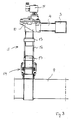
- Figure 1 shows a cleaning installation for pressurised air blast cleaning for removal of sediments inside a heat exchanger, boiler or similar preferably tubular installation.
- the installation comprises a number of valve assemblies 1 connected to a vessel 2 of pressurised air.
- the vessel 2 is in communication with the individual valve assemblies 1 through a main line 3 and associated supply lines 4.
- the valve assemblies are controlled by a control system (not shown) by which the operating cycle of the individual valve assemblies 1 and the cleaning cycle as a whole is commanded.
- valve assembly 1 is shown in detail in figures 2 and 3.
- the valve assembly 1 comprises a solenoid valve 10 which is provided control means 11 for controlling the valve 10.
- the valve 10 is supplied with pressurised air from the supply lines 3, 4.
- pressurised air is blasted into a flow passage 5 and into a flow channel 9 of a processing system, such as a boiler or the reverse chamber in a heat exchanger.
- the flow passage 5 comprises in the preferred embodiment of the invention a double walled tubular structure comprising an inner tubular member 7 and an outer tubular member 6 arranged concentrically.
- the outer member 6 is provided with an air inlet 8 through which air can be drawn or forced (not shown) into the annular space between the two tubular members 6, 7. From this annular space, air is drawn into the end section of the flow passage 15 where a cushion of air is formed, thus preventing the flue gasses in the flow channel 9 from entering the flow passage and coming into contact with the components of the valve 10.
- Air or any similar protective gas can be sucked in towards the flow channel 9 due to the flow of gas in the flow channel 9.
- air can be supplied by connecting an air or a gas supply with the air inlet 8.
- valve assembly 1 is shown in a fixed installation.
- valve 10 is connected with the flow channel 9 by a flexible tubular piece 12 secured by tightening means 13 at the two ends.
- a valve assembly 1 is shown.
- the diaphragm valve 10 comprises a first and a second chamber separated by a diaphragm or a membrane (not shown).
- the valve 10 is operated by control means, such as a solenoid valve or the like.
- control means such as a solenoid valve or the like.
- pressurised air flows from the first chamber to the valve outlet and into the flow passage 5.
- the diaphragm is provided with a small aperture through which the pressurised air flows into the second chamber and fills this chamber with air, so that equal pressures are established on both sides of the membrane/diaphragm.
- the pressure in the second chamber is applied to the entire surface of the membrane whereas only a minor portion of the membrane is subjected to the pressure in the first chamber. This presses the membrane against the valve exit and keeps the valve shut.
- the second chamber is in communication with atmospheric pressure through a ventilation opening in the control valve.
- a piston of the control valve will keep the ventilation opening shut by retaining pressure in the second chamber and thereby keep the valve shut between the blast-cleaning shuts.
- the piston is retracted and the pressurised retention air of the second chamber is quickly released out through the ventilation opening 18.
- the opening 18 is provided with an air flow tube 16 connected to the inlet 8 of the flow passage device 5 at the opposite end.
- FIG 5 a modification of the embodiment of figure 4 is shown.
- the tubular pipe 16 is provided with an external supply of cool air through a conduit 17.
- external air may still be sucked into the flow passage through the inlet 8.
- the external air may either be atmospheric air or any other gaseous air supply.
Landscapes
- Engineering & Computer Science (AREA)
- Mechanical Engineering (AREA)
- General Engineering & Computer Science (AREA)
- Chemical & Material Sciences (AREA)
- Combustion & Propulsion (AREA)
- Filtering Of Dispersed Particles In Gases (AREA)
- Incineration Of Waste (AREA)
- Cleaning By Liquid Or Steam (AREA)
- Separation Of Particles Using Liquids (AREA)
- Carbon And Carbon Compounds (AREA)
- Separation Using Semi-Permeable Membranes (AREA)
Priority Applications (2)
| Application Number | Priority Date | Filing Date | Title |
|---|---|---|---|
| EP01200244A EP1134537B1 (fr) | 2000-02-23 | 2001-01-24 | Installation de nettoyage pour l'extraction de la suie |
| DK01200244T DK1134537T3 (da) | 2000-02-23 | 2001-01-24 | Renseanlæg til fjernelse af sod |
Applications Claiming Priority (5)
| Application Number | Priority Date | Filing Date | Title |
|---|---|---|---|
| EP00200630A EP1128151A1 (fr) | 2000-02-23 | 2000-02-23 | Installation de nettoyage pour l'extraction de la suie |
| EP00200630 | 2000-02-23 | ||
| EP00201547 | 2000-05-01 | ||
| EP00201547 | 2000-05-01 | ||
| EP01200244A EP1134537B1 (fr) | 2000-02-23 | 2001-01-24 | Installation de nettoyage pour l'extraction de la suie |
Publications (3)
| Publication Number | Publication Date |
|---|---|
| EP1134537A2 true EP1134537A2 (fr) | 2001-09-19 |
| EP1134537A3 EP1134537A3 (fr) | 2001-09-26 |
| EP1134537B1 EP1134537B1 (fr) | 2004-10-13 |
Family
ID=26071888
Family Applications (1)
| Application Number | Title | Priority Date | Filing Date |
|---|---|---|---|
| EP01200244A Expired - Lifetime EP1134537B1 (fr) | 2000-02-23 | 2001-01-24 | Installation de nettoyage pour l'extraction de la suie |
Country Status (6)
| Country | Link |
|---|---|
| US (1) | US6588049B2 (fr) |
| EP (1) | EP1134537B1 (fr) |
| AT (1) | ATE279708T1 (fr) |
| DE (1) | DE60106313T2 (fr) |
| DK (1) | DK1134537T3 (fr) |
| ES (1) | ES2230230T3 (fr) |
Cited By (3)
| Publication number | Priority date | Publication date | Assignee | Title |
|---|---|---|---|---|
| WO2010122054A1 (fr) | 2009-04-21 | 2010-10-28 | Okr Cleaning Aps | Dispositif et installation de nettoyage pour retirer des suies ou similaires |
| CN111928725A (zh) * | 2020-08-20 | 2020-11-13 | 福州市闽清县通顺科技有限公司 | 一种具有自动清理滤板功能的热交换器管道酸化除垢装置 |
| IT201900019154A1 (it) * | 2019-10-17 | 2021-04-17 | Luigi Madrigali | Soffiatore per la pulizia interna di forni a legna per pizza |
Families Citing this family (7)
| Publication number | Priority date | Publication date | Assignee | Title |
|---|---|---|---|---|
| WO2007104036A2 (fr) * | 2006-03-08 | 2007-09-13 | Hni Technologies Inc. | Poêle à granulés |
| US7882707B2 (en) * | 2008-08-04 | 2011-02-08 | Lawrence Dean Leabo | Refrigeration hot gas desuperheater systems |
| GB2507346A (en) * | 2012-10-29 | 2014-04-30 | Edwards Ltd | Burner inlet assembly for generating a fluid pulse to assist in residue removal |
| RU2658064C1 (ru) * | 2017-06-08 | 2018-06-19 | Павел Евгеньевич Пособило | Очистительное устройство и способ очистки поверхностей от вредных отложений |
| KR102078173B1 (ko) * | 2020-01-08 | 2020-04-02 | 주식회사 스타인더스트리 | 선박배기관의 그을음 제거를 위한 펄스밸브 |
| CN111473350B (zh) * | 2020-04-20 | 2024-07-12 | 华电电力科学研究院有限公司 | 一种水平烟道积灰清理系统及其工作方法 |
| CN115606838B (zh) * | 2022-10-20 | 2024-05-10 | 河南中烟工业有限责任公司 | 节能型吸丝箱入口管道清洁控制系统 |
Family Cites Families (13)
| Publication number | Priority date | Publication date | Assignee | Title |
|---|---|---|---|---|
| US2897532A (en) * | 1959-08-04 | Retractable soot blower of the long travel type | ||
| US3375980A (en) * | 1966-07-21 | 1968-04-02 | Hydro Services Inc | Water blast control system |
| US3816871A (en) * | 1972-08-04 | 1974-06-18 | Copes Vulcan Inc | Soot blower lance |
| US4204496A (en) * | 1976-11-08 | 1980-05-27 | Kobe Steel, Ltd. | Steel-pipe coating apparatus |
| US4173808A (en) * | 1979-01-05 | 1979-11-13 | Combustion Engineering, Inc. | Soot blower for tube bundle in pressurized enclosure |
| US4359800A (en) * | 1981-03-05 | 1982-11-23 | The Babcock & Wilcox Company | Sootblower feed and lance tube structure with improved turbulizer system |
| DE3409995C1 (de) * | 1984-03-19 | 1985-03-14 | Norsk Hydro Magnesiumgesellschaft mbH, 4300 Essen | Steigrohr, insbesondere für eine Niederdruck-Gießvorrichtung |
| DE3427088C2 (de) * | 1984-07-18 | 1987-05-07 | Korf Engineering GmbH, 4000 Düsseldorf | Vorrichtung zum Abkühlen eines heißen Produktgases |
| US5241723A (en) * | 1991-10-21 | 1993-09-07 | The Babcock & Wilcox Company | Nozzle structure with improved stream coherence |
| US5355844A (en) * | 1993-05-26 | 1994-10-18 | Kendrick William E | System for slag removal and the like |
| US5320072A (en) * | 1993-06-07 | 1994-06-14 | B&W Nuclear Service Company | Apparatus for removing sludge deposits |
| US5724829A (en) * | 1996-02-08 | 1998-03-10 | Schubach; Frank | Chiller heating assembly |
| SE9700896L (sv) | 1997-03-13 | 1998-02-09 | Kockum Sonics Ab | Ljudgenerator |
-
2001
- 2001-01-24 ES ES01200244T patent/ES2230230T3/es not_active Expired - Lifetime
- 2001-01-24 EP EP01200244A patent/EP1134537B1/fr not_active Expired - Lifetime
- 2001-01-24 DK DK01200244T patent/DK1134537T3/da active
- 2001-01-24 DE DE60106313T patent/DE60106313T2/de not_active Expired - Lifetime
- 2001-01-24 AT AT01200244T patent/ATE279708T1/de active
- 2001-02-01 US US09/775,023 patent/US6588049B2/en not_active Expired - Lifetime
Cited By (4)
| Publication number | Priority date | Publication date | Assignee | Title |
|---|---|---|---|---|
| WO2010122054A1 (fr) | 2009-04-21 | 2010-10-28 | Okr Cleaning Aps | Dispositif et installation de nettoyage pour retirer des suies ou similaires |
| EP2246656A1 (fr) | 2009-04-21 | 2010-11-03 | OKR Cleaning Aps | Dispositif et installation de nettoyage pour l'élimination de suie ou similaires |
| IT201900019154A1 (it) * | 2019-10-17 | 2021-04-17 | Luigi Madrigali | Soffiatore per la pulizia interna di forni a legna per pizza |
| CN111928725A (zh) * | 2020-08-20 | 2020-11-13 | 福州市闽清县通顺科技有限公司 | 一种具有自动清理滤板功能的热交换器管道酸化除垢装置 |
Also Published As
| Publication number | Publication date |
|---|---|
| ATE279708T1 (de) | 2004-10-15 |
| US20010014992A1 (en) | 2001-08-23 |
| US6588049B2 (en) | 2003-07-08 |
| DE60106313D1 (de) | 2004-11-18 |
| DE60106313T2 (de) | 2006-02-23 |
| EP1134537A3 (fr) | 2001-09-26 |
| ES2230230T3 (es) | 2005-05-01 |
| DK1134537T3 (da) | 2005-02-14 |
| EP1134537B1 (fr) | 2004-10-13 |
Similar Documents
| Publication | Publication Date | Title |
|---|---|---|
| EP1134537B1 (fr) | Installation de nettoyage pour l'extraction de la suie | |
| US6739426B2 (en) | Low-noise pressure reduction system | |
| GB2473130A (en) | Filter cleaning | |
| RU2229318C2 (ru) | Пламегаситель | |
| MY134345A (en) | Device for cooling coolant in a gas turbine (2) and gas and steam turbine with said device | |
| KR19980703817A (ko) | 조합 열교환기 및 소음기 장치 | |
| CA2117870A1 (fr) | Raccord d'admission pour generateur de vapeur a recuperation de chaleur | |
| EP1128151A1 (fr) | Installation de nettoyage pour l'extraction de la suie | |
| ES2098924T3 (es) | Valvula de conversion de vapor. | |
| SU1123549A3 (ru) | Котельный глушитель шума | |
| EP2422156B1 (fr) | Dispositif et installation de nettoyage pour l'élimination de suie ou similaires | |
| RU2194938C2 (ru) | Пневмоимпульсная установка | |
| CN210291931U (zh) | 一种变频声波吹灰装置系统 | |
| JPH10122763A (ja) | 流体への熱伝達システム、同熱伝達用組立体、同熱伝達プロセス、該システムの又は該組立体の使用 | |
| JP4026023B2 (ja) | ボイラ | |
| KR102571966B1 (ko) | 작동 유체 가열 설비용 소음 방지 시스템 | |
| CN219433864U (zh) | 火力发电系统及其换热装置 | |
| KR20210067361A (ko) | 어쿠스틱 수트 블로워 | |
| CN218328112U (zh) | 一种防积灰的锅炉过热器 | |
| CN212587213U (zh) | 一种大流量蒸汽打靶消音器 | |
| JP3117274B2 (ja) | 集じん装置 | |
| GB2059025A (en) | Water heating boiler unit | |
| KR200323381Y1 (ko) | 안전 밸브 배출 배관의 역류 방지용 드립 팬 장치 | |
| DE69423779D1 (de) | Wärmetauscher | |
| RU2003107994A (ru) | Энергоблок |
Legal Events
| Date | Code | Title | Description |
|---|---|---|---|
| PUAI | Public reference made under article 153(3) epc to a published international application that has entered the european phase |
Free format text: ORIGINAL CODE: 0009012 |
|
| PUAL | Search report despatched |
Free format text: ORIGINAL CODE: 0009013 |
|
| AK | Designated contracting states |
Kind code of ref document: A2 Designated state(s): AT BE CH CY DE DK ES FI FR GB GR IE IT LI LU MC NL PT SE TR |
|
| AX | Request for extension of the european patent |
Free format text: AL;LT;LV;MK;RO;SI |
|
| AK | Designated contracting states |
Kind code of ref document: A3 Designated state(s): AT BE CH CY DE DK ES FI FR GB GR IE IT LI LU MC NL PT SE TR |
|
| AX | Request for extension of the european patent |
Free format text: AL;LT;LV;MK;RO;SI |
|
| RAP3 | Party data changed (applicant data changed or rights of an application transferred) |
Owner name: OKR CLEANING |
|
| 17P | Request for examination filed |
Effective date: 20020320 |
|
| AKX | Designation fees paid |
Free format text: AT BE CH CY DE DK ES FI FR GB GR IE IT LI LU MC NL PT SE TR |
|
| 17Q | First examination report despatched |
Effective date: 20030109 |
|
| RAP1 | Party data changed (applicant data changed or rights of an application transferred) |
Owner name: OKR CLEANING |
|
| GRAP | Despatch of communication of intention to grant a patent |
Free format text: ORIGINAL CODE: EPIDOSNIGR1 |
|
| GRAS | Grant fee paid |
Free format text: ORIGINAL CODE: EPIDOSNIGR3 |
|
| GRAA | (expected) grant |
Free format text: ORIGINAL CODE: 0009210 |
|
| AK | Designated contracting states |
Kind code of ref document: B1 Designated state(s): AT BE CH CY DE DK ES FI FR GB GR IE IT LI LU MC NL PT SE TR |
|
| PG25 | Lapsed in a contracting state [announced via postgrant information from national office to epo] |
Ref country code: NL Free format text: LAPSE BECAUSE OF FAILURE TO SUBMIT A TRANSLATION OF THE DESCRIPTION OR TO PAY THE FEE WITHIN THE PRESCRIBED TIME-LIMIT Effective date: 20041013 Ref country code: TR Free format text: LAPSE BECAUSE OF FAILURE TO SUBMIT A TRANSLATION OF THE DESCRIPTION OR TO PAY THE FEE WITHIN THE PRESCRIBED TIME-LIMIT Effective date: 20041013 |
|
| REG | Reference to a national code |
Ref country code: GB Ref legal event code: FG4D |
|
| REG | Reference to a national code |
Ref country code: CH Ref legal event code: EP |
|
| REG | Reference to a national code |
Ref country code: IE Ref legal event code: FG4D |
|
| REF | Corresponds to: |
Ref document number: 60106313 Country of ref document: DE Date of ref document: 20041118 Kind code of ref document: P |
|
| PG25 | Lapsed in a contracting state [announced via postgrant information from national office to epo] |
Ref country code: GR Free format text: LAPSE BECAUSE OF FAILURE TO SUBMIT A TRANSLATION OF THE DESCRIPTION OR TO PAY THE FEE WITHIN THE PRESCRIBED TIME-LIMIT Effective date: 20050113 |
|
| PG25 | Lapsed in a contracting state [announced via postgrant information from national office to epo] |
Ref country code: LU Free format text: LAPSE BECAUSE OF NON-PAYMENT OF DUE FEES Effective date: 20050124 Ref country code: CY Free format text: LAPSE BECAUSE OF FAILURE TO SUBMIT A TRANSLATION OF THE DESCRIPTION OR TO PAY THE FEE WITHIN THE PRESCRIBED TIME-LIMIT Effective date: 20050124 |
|
| PG25 | Lapsed in a contracting state [announced via postgrant information from national office to epo] |
Ref country code: MC Free format text: LAPSE BECAUSE OF NON-PAYMENT OF DUE FEES Effective date: 20050131 |
|
| REG | Reference to a national code |
Ref country code: CH Ref legal event code: NV Representative=s name: TROESCH SCHEIDEGGER WERNER AG |
|
| REG | Reference to a national code |
Ref country code: SE Ref legal event code: TRGR |
|
| REG | Reference to a national code |
Ref country code: DK Ref legal event code: T3 |
|
| NLV1 | Nl: lapsed or annulled due to failure to fulfill the requirements of art. 29p and 29m of the patents act | ||
| REG | Reference to a national code |
Ref country code: ES Ref legal event code: FG2A Ref document number: 2230230 Country of ref document: ES Kind code of ref document: T3 |
|
| PLBE | No opposition filed within time limit |
Free format text: ORIGINAL CODE: 0009261 |
|
| STAA | Information on the status of an ep patent application or granted ep patent |
Free format text: STATUS: NO OPPOSITION FILED WITHIN TIME LIMIT |
|
| ET | Fr: translation filed | ||
| 26N | No opposition filed |
Effective date: 20050714 |
|
| REG | Reference to a national code |
Ref country code: CH Ref legal event code: PUE Owner name: OKR CLEANING APS Free format text: OKR CLEANING#PETERSMINDEVEJ 5, PORT 104#DK-8362 HORNING (DK) -TRANSFER TO- OKR CLEANING APS#STENBAEKVEJ 21#8220 BRABRAND (DK) |
|
| REG | Reference to a national code |
Ref country code: GB Ref legal event code: 732E |
|
| REG | Reference to a national code |
Ref country code: FR Ref legal event code: TP |
|
| REG | Reference to a national code |
Ref country code: ES Ref legal event code: PC2A |
|
| PG25 | Lapsed in a contracting state [announced via postgrant information from national office to epo] |
Ref country code: PT Free format text: LAPSE BECAUSE OF NON-PAYMENT OF DUE FEES Effective date: 20050313 |
|
| REG | Reference to a national code |
Ref country code: CH Ref legal event code: PFA Owner name: AEROVIT A/S Free format text: OKR CLEANING APS#STENBAEKVEJ 21#8220 BRABRAND (DK) -TRANSFER TO- AEROVIT A/S#KORDEN 15#8751 GEDVED (DK) |
|
| REG | Reference to a national code |
Ref country code: ES Ref legal event code: PC2A Owner name: AEROVIT A/S Effective date: 20120605 |
|
| REG | Reference to a national code |
Ref country code: DE Ref legal event code: R081 Ref document number: 60106313 Country of ref document: DE Owner name: AEROVIT A/S, DK Free format text: FORMER OWNER: OKR CLEANING APS, BRABRAND, DK Effective date: 20120516 Ref country code: DE Ref legal event code: R082 Ref document number: 60106313 Country of ref document: DE Representative=s name: TBK, DE Effective date: 20120516 |
|
| REG | Reference to a national code |
Ref country code: AT Ref legal event code: PC Ref document number: 279708 Country of ref document: AT Kind code of ref document: T Owner name: AEROVIT A/S, DK Effective date: 20120522 |
|
| REG | Reference to a national code |
Ref country code: FR Ref legal event code: CD Owner name: AEROVIT A/S, DK Effective date: 20121119 |
|
| REG | Reference to a national code |
Ref country code: FR Ref legal event code: PLFP Year of fee payment: 15 |
|
| REG | Reference to a national code |
Ref country code: FR Ref legal event code: PLFP Year of fee payment: 16 |
|
| REG | Reference to a national code |
Ref country code: FR Ref legal event code: PLFP Year of fee payment: 17 |
|
| REG | Reference to a national code |
Ref country code: FR Ref legal event code: PLFP Year of fee payment: 18 |
|
| PGFP | Annual fee paid to national office [announced via postgrant information from national office to epo] |
Ref country code: FR Payment date: 20190122 Year of fee payment: 19 Ref country code: GB Payment date: 20190122 Year of fee payment: 19 Ref country code: DE Payment date: 20190128 Year of fee payment: 19 Ref country code: FI Payment date: 20190124 Year of fee payment: 19 Ref country code: IT Payment date: 20190122 Year of fee payment: 19 Ref country code: CH Payment date: 20190128 Year of fee payment: 19 Ref country code: ES Payment date: 20190204 Year of fee payment: 19 Ref country code: IE Payment date: 20190122 Year of fee payment: 19 |
|
| PGFP | Annual fee paid to national office [announced via postgrant information from national office to epo] |
Ref country code: SE Payment date: 20190122 Year of fee payment: 19 Ref country code: AT Payment date: 20190131 Year of fee payment: 19 Ref country code: BE Payment date: 20190123 Year of fee payment: 19 Ref country code: DK Payment date: 20190130 Year of fee payment: 19 |
|
| REG | Reference to a national code |
Ref country code: DE Ref legal event code: R119 Ref document number: 60106313 Country of ref document: DE |
|
| REG | Reference to a national code |
Ref country code: FI Ref legal event code: MAE |
|
| REG | Reference to a national code |
Ref country code: DK Ref legal event code: EBP Effective date: 20200131 Ref country code: CH Ref legal event code: PL |
|
| REG | Reference to a national code |
Ref country code: SE Ref legal event code: EUG |
|
| REG | Reference to a national code |
Ref country code: AT Ref legal event code: MM01 Ref document number: 279708 Country of ref document: AT Kind code of ref document: T Effective date: 20200124 |
|
| GBPC | Gb: european patent ceased through non-payment of renewal fee |
Effective date: 20200124 |
|
| REG | Reference to a national code |
Ref country code: SE Ref legal event code: EUG |
|
| REG | Reference to a national code |
Ref country code: BE Ref legal event code: MM Effective date: 20200131 |
|
| PG25 | Lapsed in a contracting state [announced via postgrant information from national office to epo] |
Ref country code: SE Free format text: LAPSE BECAUSE OF NON-PAYMENT OF DUE FEES Effective date: 20200125 Ref country code: FI Free format text: LAPSE BECAUSE OF NON-PAYMENT OF DUE FEES Effective date: 20200124 Ref country code: FR Free format text: LAPSE BECAUSE OF NON-PAYMENT OF DUE FEES Effective date: 20200131 Ref country code: GB Free format text: LAPSE BECAUSE OF NON-PAYMENT OF DUE FEES Effective date: 20200124 Ref country code: DE Free format text: LAPSE BECAUSE OF NON-PAYMENT OF DUE FEES Effective date: 20200801 |
|
| PG25 | Lapsed in a contracting state [announced via postgrant information from national office to epo] |
Ref country code: LI Free format text: LAPSE BECAUSE OF NON-PAYMENT OF DUE FEES Effective date: 20200131 Ref country code: CH Free format text: LAPSE BECAUSE OF NON-PAYMENT OF DUE FEES Effective date: 20200131 Ref country code: AT Free format text: LAPSE BECAUSE OF NON-PAYMENT OF DUE FEES Effective date: 20200124 Ref country code: BE Free format text: LAPSE BECAUSE OF NON-PAYMENT OF DUE FEES Effective date: 20200131 |
|
| PG25 | Lapsed in a contracting state [announced via postgrant information from national office to epo] |
Ref country code: DK Free format text: LAPSE BECAUSE OF NON-PAYMENT OF DUE FEES Effective date: 20200131 Ref country code: IE Free format text: LAPSE BECAUSE OF NON-PAYMENT OF DUE FEES Effective date: 20200124 Ref country code: IT Free format text: LAPSE BECAUSE OF NON-PAYMENT OF DUE FEES Effective date: 20200124 |
|
| REG | Reference to a national code |
Ref country code: ES Ref legal event code: FD2A Effective date: 20210604 |
|
| PG25 | Lapsed in a contracting state [announced via postgrant information from national office to epo] |
Ref country code: ES Free format text: LAPSE BECAUSE OF NON-PAYMENT OF DUE FEES Effective date: 20200125 |