EP1134589A2 - Verfahren zur Detektion einer fehlerhaften Masseverbindung in einer elektrischen Einrichtung insbesondere eines Kraftfahrzeugs - Google Patents
Verfahren zur Detektion einer fehlerhaften Masseverbindung in einer elektrischen Einrichtung insbesondere eines Kraftfahrzeugs Download PDFInfo
- Publication number
- EP1134589A2 EP1134589A2 EP00127201A EP00127201A EP1134589A2 EP 1134589 A2 EP1134589 A2 EP 1134589A2 EP 00127201 A EP00127201 A EP 00127201A EP 00127201 A EP00127201 A EP 00127201A EP 1134589 A2 EP1134589 A2 EP 1134589A2
- Authority
- EP
- European Patent Office
- Prior art keywords
- ground connection
- detection
- faulty
- circuit
- voltage
- Prior art date
- Legal status (The legal status is an assumption and is not a legal conclusion. Google has not performed a legal analysis and makes no representation as to the accuracy of the status listed.)
- Granted
Links
Images


Classifications
-
- B—PERFORMING OPERATIONS; TRANSPORTING
- B60—VEHICLES IN GENERAL
- B60L—PROPULSION OF ELECTRICALLY-PROPELLED VEHICLES; SUPPLYING ELECTRIC POWER FOR AUXILIARY EQUIPMENT OF ELECTRICALLY-PROPELLED VEHICLES; ELECTRODYNAMIC BRAKE SYSTEMS FOR VEHICLES IN GENERAL; MAGNETIC SUSPENSION OR LEVITATION FOR VEHICLES; MONITORING OPERATING VARIABLES OF ELECTRICALLY-PROPELLED VEHICLES; ELECTRIC SAFETY DEVICES FOR ELECTRICALLY-PROPELLED VEHICLES
- B60L3/00—Electric devices on electrically-propelled vehicles for safety purposes; Monitoring operating variables, e.g. speed, deceleration or energy consumption
- B60L3/10—Indicating wheel slip ; Correction of wheel slip
- B60L3/102—Indicating wheel slip ; Correction of wheel slip of individual wheels
-
- G—PHYSICS
- G01—MEASURING; TESTING
- G01R—MEASURING ELECTRIC VARIABLES; MEASURING MAGNETIC VARIABLES
- G01R31/00—Arrangements for testing electric properties; Arrangements for locating electric faults; Arrangements for electrical testing characterised by what is being tested not provided for elsewhere
- G01R31/005—Testing of electric installations on transport means
- G01R31/006—Testing of electric installations on transport means on road vehicles, e.g. automobiles or trucks
-
- G—PHYSICS
- G01—MEASURING; TESTING
- G01R—MEASURING ELECTRIC VARIABLES; MEASURING MAGNETIC VARIABLES
- G01R31/00—Arrangements for testing electric properties; Arrangements for locating electric faults; Arrangements for electrical testing characterised by what is being tested not provided for elsewhere
- G01R31/50—Testing of electric apparatus, lines, cables or components for short-circuits, continuity, leakage current or incorrect line connections
- G01R31/52—Testing for short-circuits, leakage current or ground faults
-
- G—PHYSICS
- G01—MEASURING; TESTING
- G01R—MEASURING ELECTRIC VARIABLES; MEASURING MAGNETIC VARIABLES
- G01R31/00—Arrangements for testing electric properties; Arrangements for locating electric faults; Arrangements for electrical testing characterised by what is being tested not provided for elsewhere
- G01R31/50—Testing of electric apparatus, lines, cables or components for short-circuits, continuity, leakage current or incorrect line connections
- G01R31/54—Testing for continuity
Definitions
- the invention relates to a method for detecting a faulty ground connection in an electrical device, in particular a motor vehicle, according to the Preamble of claim 1.
- the object of the invention is a generic method for the detection of to develop faulty ground connections, the one in terms of switching elements switch-independent detection enabled.
- the invention makes use of the knowledge that the faultiness of a Earth connection not always by completely loosening the earth connection expresses, but that by loosening or corrosion transition resistance arise that result in a voltage drop at the ground connection.
- This Voltage drops are achieved using the two-step method according to the invention detected.
- a reference value of a detection parameter is determined, the only error-free ground connections.
- This reference value is in the electrical Device of the motor vehicle stored. Is the motor vehicle after leaving the Production plant in driving operation, so in the second process step measured value identifying the respective driving operation. Does the measured value agree? the stored reference value, there are faultless ground connections.
- the Fact concluded that one or more of the measured ground connections is or are faulty. From the type of deviation of the measured value from the For a corresponding detection device, the reference value can also be seen which the ground connections are faulty. In response to this an error message.
- a further development of the invention provides that after an error message has been transmitted a faultless ground connection by means of one connected to the ground connections Bypass circuit is switched on.
- This has the advantage that during the operation of the corresponding motor vehicle, the subsystem whose Ground connection is faulty, is completely connected to ground again.
- One Failure of the corresponding subsystem due to the networking of the subsystems with each other sometimes a failure of the complete electrical equipment of the This can prevent motor vehicles from following.
- the error message is by means of a ground connection connected signaling circuit in the form of an externally perceptible signal.
- the signal can be transmitted, for example, in such a way that it is for the driver of the vehicle Motor vehicle is perceptible or retrievable at any time.
- the bypass circuit is a failure of the defective Ground system associated subsystem prevented and at the same time the driver it is signaled that changes have been initiated in the electrical device are and a visit to a workshop is advisable.
- the error message by means of a signaling circuit connected to the ground connections in a storage means the electrical device is deposited.
- This has the advantage that the next routine inspection of the motor vehicle in the workshop Automotive technician after connecting his diagnostic device to the electrical device of the motor vehicle has been brought to the knowledge that in the electrical equipment changes, in this case replacements incorrect Ground connections through faultless ground connections, were going on. Since the Detection circuit from the type of deviation of the measured value from the reference value can also determine which of the ground connections is faulty and which Notification circuit also passes this information on to the motor vehicle technician, it is for this it is easily possible to close the faulty bridged ground connection localize, replace them with a faultless ground connection and the manufactured one Cancel the bridging.
- the detection circuit is connected to it by means of a Control circuit selectively at predefinable times or continuously in predeterminable time intervals or permanently controlled.
- This training has the advantage that, depending on the frequency of use of the the respective ground connection assigned subsystem of the electrical device Frequency of detection can be varied. Because the operation of the motor vehicle always also with the operation of the control unit of the drive motor, but not at the same time that always goes hand in hand with the operation of the lighting system, for example Engine control unit in operation more often and longer than is the case with the lighting system. In the engine control unit, the probability of a fault is therefore the Ground connection larger than with the lighting system, a more frequent and longer Continuous detection of the associated ground connection is therefore meaningful and will possible by the control circuit in an advantageous manner.
- the detection parameter and the parameter of the Reference value can be used as electrical voltage. Electrical voltages can be electrically connected to the ground connections in a particularly simple manner connected resistor network can be tapped. Both to determine the Reference voltage value as well as used to determine the detection voltage value one advantageously looks at the same resistor network, which is the number of used components reduced.
- Figure 1 shows an electrical device 1 of a motor vehicle (not shown).
- the Device 1 has a detection device 2 and a first subsystem 3 and second subsystem 4.
- the first subsystem 3 and the second subsystem 4 are electrically connected both to the detection device 2 and to a mass 5.
- an electrical connection 7 leaves the first subsystem 3 at a point 6 and runs over a branch point 8 and a ground connection 9 to one Ground 5.
- an electrical connection 11 leaves the second subsystem 4 and runs over a branch point 12 and one Ground connection 13 also to ground 5.
- One branches at branch point 8 electrical connection 14 from the electrical connection 7 and sets at one Point 15 establishes the electrical connection to the detection device 2.
- Corresponding at the junction point 12 branches an electrical connection 16 from the electrical connection 11 and also occurs at a point 17 with the Detection device 2 electrically connected.
- FIG. 2 shows schematically the subcircuits from which the detection device 2 is made put together.
- the most important of these subcircuits is a detection circuit 18.
- the detection circuit 18 speaks as soon as the faulty one Ground connection has recognized a bypass circuit 19, which is shown in FIG is symbolically represented by an arrow 20.
- the detection circuit 18 speaks in
- a signaling circuit 21 is also activated on the one hand, issues a report to the driver of the motor vehicle, another for the automotive technician of a workshop a corresponding message in the electrical device 1 of the motor vehicle stored in memory.
- the Action of the detection circuit 18 on the signaling circuit 21 is shown in FIG Arrow 22 illustrated.
- the Detection circuit 18 checks the ground connections for defects, is checked by means of a control circuit 23.
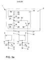
- Figures 3a, 3b and 3c show a preferred embodiment of the Detection circuit 18, which in the detection device 2 of the electrical device 1st of the motor vehicle is installed.
- the same components have the same reference numerals provided in Figures 1 and 2, so that in this respect reference was made to the description there can be.
- FIG. 3a shows the detection circuit 18 and its electrical parameters for the Case of two error-free ground connections 9 and 13.
- the detection circuit 18 points a voltage source 24 through which it is supplied with an electrical voltage of for example, 5 volts is supplied.
- the voltage source 24 is electrical Connection 25 with a resistor 26 in connection.
- Via an electrical Connection 27 is the resistor 26 with a further resistor 28 in Connection.
- An electrical connection 29 establishes the connection to point 15.
- the electrical connection 27 has a branch point 30, which is the electrical Connection 27 via an electrical connection 31 to a voltage measuring device 32 connects.
- the connection between the voltage measuring device 32 and the point 17 finally establishes an electrical connection 33.
- FIG. 3a shows the situation that is necessary for determining the reference voltage, that is, for determining the voltage that is assigned to the case of fault-free ground connections.
- the two ground connections 9 and 13 thus have vanishing contact resistances R 1 and R2, at which a voltage of 0 volts therefore drops in each case.
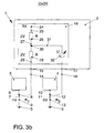
- FIG. 3b shows the detection device 2 for the case of a faulty ground connection 9 and a faultless ground connection 13.
- the faulty ground connection 9 requires a contact resistance R 1 , at which a voltage of 1 volt drops.
- the fault-free ground connection 13 causes a vanishing contact resistance R2, which is why the voltage drop across the ground connection 13 is 0 volts.
- Both the resistor 26 and the resistor 28 of the voltage divider of the detection circuit 18 drop 2 volts, which is why the voltage measuring device 32 displays the sum of the voltage drops across the resistor 28 and at the ground connection 9, that is to say a detection voltage of 3 volts.
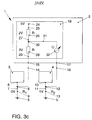
- FIG. 3c shows the determination of the detection voltage in the event that the ground connection 9 is faultless and the ground connection 13 is faulty.
- the ground connection 9 causes a disappearing contact resistance R 1 and an associated voltage drop of 0 volts
- the ground connection 13 has a non-disappearing contact resistance R 2 , at which a voltage of 1 volt drops. 2 volts drop across resistor 26 and 3 volts drop across resistor 28. Since the voltage measuring device 32 does not measure the 3 volts dropping across the resistor 28 against the ground 5, but against the voltage drop of 1 volt at the ground connection 13, it displays a detection voltage of 2 volts corresponding to the difference between the two voltages.
- FIGS. 3a, 3b and 3c show how the Detection circuit 18 the following clearly:
- the in the circuit of Figure 3a on the Voltage measuring device 32 detected voltage of 2.5 volts is the reference voltage since in this case, both ground connections 9 and 13 are error-free.
- the voltage of 3 volts detected by FIG. 3b is the detection voltage for the case a faulty ground connection 9, whereas those in the circuit according to FIG. 3c measured voltage of 2 volts indicates the faultiness of the ground connection 13.
- Detect detection voltages that exceed the reference voltage of 2.5 volts hence a fault in the ground connection 9, whereas one If the reference voltage falls below a fault in the ground connection 13 is present. It is therefore easy to locate the faulty ground connection.
- the embodiment just described shows an electrical device with two Subsystems. Of course, there are also more than two subsystems or only a single electrical subsystem can be used. In this last one The case would be the reference voltage with a faultless ground connection 0 volts. Each Detection voltage (which in this case is directly related to the voltage drop across the Ground connection corresponds), the amount of which is greater than zero, would indicate the faultiness indicate the ground connection.
- the function was purely exemplary above explained using a voltage measurement, of course can also be done via a Current measurement a faulty ground connection can be determined.
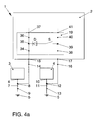
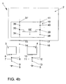
- FIGS. 4a and 4b show two embodiments of the bypass circuit 19, which are built into the detection device 2 of the electrical device 1.
- the point 15 is connected to an electrical connection 34 Junction point 35 electrically connected.
- the branch point 35 is over a electrical connection 36 connected to a point 37 at which, for example, the Detection circuit 18 can be connected.
- the electrical connections 34 and 36, the branch point 35 and the point 37 of the first subsystem 3 In the second subsystem 4, the electrical connections 38 and 40 correspond to the Branch point 39 and point 41.
- the bypass circuit 19 is in the embodiment according to FIG. 4a Series connection of a diode D and a switch S realized between the Branch points 35 and 39 are located.
- FIG. 4b shows a switching element SE in the bypass circuit 19, in particular semiconductor switching element, which as a bipolar transistor, unipolar transistor or the like can be realized.
- semiconductor switching element which as a bipolar transistor, unipolar transistor or the like can be realized.
- the effect between the Junction points 35 and 39 electronic components located a conductive Connection between the ground connections 9 and 13, that is, one Parallel connection or a complete switch from one to the other Ground connection.
Landscapes
- Engineering & Computer Science (AREA)
- General Physics & Mathematics (AREA)
- Physics & Mathematics (AREA)
- Power Engineering (AREA)
- Sustainable Development (AREA)
- Sustainable Energy (AREA)
- Life Sciences & Earth Sciences (AREA)
- Transportation (AREA)
- Mechanical Engineering (AREA)
- Chemical & Material Sciences (AREA)
- Combustion & Propulsion (AREA)
- Testing Of Short-Circuits, Discontinuities, Leakage, Or Incorrect Line Connections (AREA)
- Electric Propulsion And Braking For Vehicles (AREA)
- Control Of Electric Motors In General (AREA)
- Automatic Cycles, And Cycles In General (AREA)
Abstract
- Ermitteln eines Messwerts eines Detektionsparameters mittels einer mit wenigstens einer Masseverbindung (9,13) verbundenen Detektionsschaltung (18);
- Vergleichen des ermittelten Messwerts mit einem festlegbaren Referenzwert;
- Feststellen einer fehlerhaften Masseverbindung bei Überschreiten des Messwerts über den Referenzwert;
- Übermitteln einer Fehlermeldung bei festgestellter fehlerhafter Masseverbindung.
Description
- Ermitteln eines Messwerts eines Detektionsparameters mittels einer mit wenigstens einer Masseverbindung verbundenen Detektionsschaltung;
- Vergleichen des ermittelten Messwerts mit einem festlegbaren Referenzwert;
- Festlegen einer fehlerhaften Masseverbindung bei Überschreiten des Messwerts über den Referenzwert;
- Übermitteln einer Fehlermeldung bei festgestellter fehlerhafter Masseverbindung.
- Figur 1
- eine erfindungsgemäße Detektionsvorrichtung und zwei Teilsysteme einer elektrischen Einrichtung eines Kraftfahrzeugs als Schaltbild;
- Figur 2
- die Detektionsvorrichtung in schematischer Darstellung;
- Figur 3a, 3b, 3c
- eine erfindungsgemäße Detektionsschaltung, die mit verschiedenen Kombinationen fehlerhafter Masseverbindungen verbunden ist, sowie
- Figur 4a, 4b
- jeweils eine bevorzugte Ausführungsform einer erfindungsgemäßen Überbrückungsschaltung.
Claims (6)
- Verfahren zur Detektion einer fehlerhaften Masseverbindung in einer elektrischen Einrichtung insbesondere eines Kraftfahrzeugs, gekennzeichnet durch folgende Verfahrensschritte:Ermitteln eines Messwerts eines Detektionsparameters mittels einer mit wenigstens einer Masseverbindung (9,13) verbundenen Detektionsschaltung (18);Vergleichen des ermittelten Messwerts mit einem festlegbaren Referenzwert;Feststellen einer fehlerhaften Masseverbindung bei Überschreiten des Messwerts über den Referenzwert;Übermitteln einer Fehlermeldung bei festgestellter fehlerhafter Masseverbindung.
- Verfahren nach Anspruch 1, dadurch gekennzeichnet, dass nach Übermittlung einer Fehlermeldung eine fehlerfreie Masseverbindung mittels einer mit den Masseverbindungen (9,13) verbundenen Überbrückungsschaltung (19) zugeschaltet wird.
- Verfahren nach einem der vorhergehenden Ansprüche, dadurch gekennzeichnet, dass die Fehlermeldung mittels einer mit den Masseverbindungen (9,13) verbundenen Meldeschaltung (21) in Form eines von außen wahrnehmbaren Signals erfolgt.
- Verfahren nach einem der vorhergehenden Ansprüche, dadurch gekennzeichnet, dass die Fehlermeldung mittels einer mit den Masseverbindungen (9,13) verbundenen Meldeschaltung (21) in einem Speichermittel der elektrischen Einrichtung (1) hinterlegt wird.
- Verfahren nach einem der vorhergehenden Ansprüche, dadurch gekennzeichnet, dass die Detektionsschaltung (18) mittels einer mit ihr verbundenen Kontrollschaltung (23) punktuell zu vorgebbaren Zeitpunkten oder kontinuierlich in vorgebbaren Zeitintervallen oder permanent kontrolliert wird.
- Verfahren nach einem der vorhergehenden Ansprüche, dadurch gekennzeichnet, dass der Detektionsparameter und der Parameter des Referenzwerts als elektrische Spannung herangezogen werden.
Applications Claiming Priority (2)
| Application Number | Priority Date | Filing Date | Title |
|---|---|---|---|
| DE10002537 | 2000-01-21 | ||
| DE10002537A DE10002537A1 (de) | 2000-01-21 | 2000-01-21 | Verfahren zur Detektion einer fehlerhaften Masseverbindung in einer elektrischen Einrichtung insbesondere eines Kraftfahrzeugs |
Publications (3)
| Publication Number | Publication Date |
|---|---|
| EP1134589A2 true EP1134589A2 (de) | 2001-09-19 |
| EP1134589A3 EP1134589A3 (de) | 2003-06-25 |
| EP1134589B1 EP1134589B1 (de) | 2005-03-23 |
Family
ID=7628291
Family Applications (1)
| Application Number | Title | Priority Date | Filing Date |
|---|---|---|---|
| EP00127201A Expired - Lifetime EP1134589B1 (de) | 2000-01-21 | 2000-12-14 | Verfahren zur Detektion einer fehlerhaften Masseverbindung in einer elektrischen Einrichtung insbesondere eines Kraftfahrzeugs |
Country Status (3)
| Country | Link |
|---|---|
| EP (1) | EP1134589B1 (de) |
| AT (1) | ATE291743T1 (de) |
| DE (2) | DE10002537A1 (de) |
Cited By (3)
| Publication number | Priority date | Publication date | Assignee | Title |
|---|---|---|---|---|
| FR2904695A1 (fr) * | 2006-12-05 | 2008-02-08 | Siemens Vdo Automotive Sas | Procede et dispositif de prevention d'un defaut de liaison a la masse d'une unite de calcul a microprocesseur |
| FR3007530A1 (fr) * | 2013-06-20 | 2014-12-26 | Continental Automotive France | Dispositif de diagnostic de la perte d'une connexion entre un module de controle electronique et une masse |
| EP4498550A1 (de) * | 2023-07-28 | 2025-01-29 | Aptiv Technologies AG | Redundantes elektrisches erdversorgungssystem |
Families Citing this family (15)
| Publication number | Priority date | Publication date | Assignee | Title |
|---|---|---|---|---|
| DE10347381B4 (de) * | 2003-10-08 | 2019-05-09 | Volkswagen Ag | Verfahren und Vorrichtung zur fehlerabgesicherten Übertragung von Nutzdaten |
| JP4050292B2 (ja) * | 2005-09-09 | 2008-02-20 | 三菱電機株式会社 | 電子制御装置 |
| DE102012215542A1 (de) | 2011-10-07 | 2013-04-11 | Robert Bosch Gmbh | Schutz- und/oder Diagnoseeinrichtung für Mehrspannungsbordnetz, Mehrspannungsbordnetz und Verfahren zum Betrieb eines Mehrspannungsbordnetzes |
| DE102012015911B3 (de) * | 2012-08-10 | 2013-10-24 | Audi Ag | Diagnoseeinrichtung zur Überprüfung einer Steuersignalleitung |
| DE102012214906A1 (de) * | 2012-08-22 | 2014-02-27 | Automotive Lighting Reutlingen Gmbh | Steuergerät für elektrische Last |
| DE102012019186B4 (de) | 2012-09-28 | 2018-10-31 | Audi Ag | Fahrzeug und Verfahren mit erhöhter Verlässlichkeit einer Masseanbindung |
| DE102013214835A1 (de) | 2013-07-30 | 2015-02-05 | Robert Bosch Gmbh | Überspannungsschutz für ein Mehrspannungsbordnetz |
| FR3011638B1 (fr) * | 2013-10-04 | 2017-05-26 | Continental Automotive France | Dispositif de diagnostic de la perte d'une connexion entre un module de controle electronique et une masse |
| CN105791525B (zh) * | 2014-12-25 | 2020-03-17 | 中兴通讯股份有限公司 | 接地调整方法及装置 |
| JP6488930B2 (ja) * | 2015-07-21 | 2019-03-27 | 株式会社デンソー | 電子制御装置 |
| DE102016102248A1 (de) * | 2016-02-10 | 2017-08-10 | Robert Bosch Automotive Steering Gmbh | Massebrucherkennung |
| DE102018220195B4 (de) | 2018-11-23 | 2020-10-01 | Leoni Bordnetz-Systeme Gmbh | Elektrisches Bordnetz sowie Verfahren zur Detektion eines fehlerhaften Anschlusselements |
| DE102019215790B4 (de) * | 2019-10-14 | 2021-11-25 | Continental Automotive Gmbh | Steuergeräteschaltung für ein Kraftfahrzeug sowie Kraftfahrzeug und Betriebsverfahren für die Steuergeräteschaltung |
| US12577920B2 (en) | 2021-12-20 | 2026-03-17 | Robert Bosch Limitada | Method for diagnosing faults in the operation of a fuel heating system associated with an internal combustion engine |
| DE102024203626A1 (de) * | 2024-04-18 | 2025-10-23 | Continental Automotive Technologies GmbH | Bremsensteuergerät mit redundanter Stromversorgung |
Family Cites Families (12)
| Publication number | Priority date | Publication date | Assignee | Title |
|---|---|---|---|---|
| US4347540A (en) * | 1981-04-27 | 1982-08-31 | Westinghouse Electric Corp. | Solid-state load protection system having ground fault sensing |
| US4725912A (en) * | 1986-06-16 | 1988-02-16 | Motorola Inc. | Power MOS loss of ground protection |
| JPH01237894A (ja) * | 1988-03-18 | 1989-09-22 | Hitachi Maxell Ltd | 半導体記録装置の端子接続検出方式 |
| DE4032423A1 (de) * | 1990-10-12 | 1992-04-16 | Bosch Gmbh Robert | Elektronisches geraet |
| IT1249525B (it) * | 1991-02-18 | 1995-02-23 | Sgs Thomson Microelectronics | Dispositivo di protezione della perdita della massa particolarmente per circuiti integrati mos |
| DE4342871A1 (de) * | 1993-12-16 | 1995-06-22 | Bosch Gmbh Robert | Anzeigeeinrichtung für ein elektrisches Steuergerät |
| DE4428115C2 (de) * | 1994-08-09 | 1997-10-16 | Hella Kg Hueck & Co | Steuergerät mit einer Schaltungsanordnung zum Schutz des Steuergerätes bei Unterbrechung der Steuergerätemasse |
| DE19611522B4 (de) * | 1996-03-23 | 2009-01-29 | Robert Bosch Gmbh | Verfahren und Vorrichtung zur Fehlererkennung bei einer Endstufenschaltungsanordnung |
| DE19723456C2 (de) * | 1997-06-04 | 2003-03-27 | Siemens Ag | Fehlschlußerkennungseinrichtung für elektrische Verbraucher |
| DE19723928A1 (de) * | 1997-06-06 | 1998-12-10 | Bosch Gmbh Robert | Vorrichtung zur Anbindung von Referenzmassen an integrierte Schaltungen |
| US5933077A (en) * | 1997-06-20 | 1999-08-03 | Wells Fargo Alarm Services, Inc. | Apparatus and method for detecting undesirable connections in a system |
| DE19751519C2 (de) * | 1997-11-21 | 2000-08-24 | Helag Electronic Gmbh | Linearsensor |
-
2000
- 2000-01-21 DE DE10002537A patent/DE10002537A1/de not_active Withdrawn
- 2000-12-14 DE DE50009861T patent/DE50009861D1/de not_active Expired - Fee Related
- 2000-12-14 EP EP00127201A patent/EP1134589B1/de not_active Expired - Lifetime
- 2000-12-14 AT AT00127201T patent/ATE291743T1/de not_active IP Right Cessation
Cited By (4)
| Publication number | Priority date | Publication date | Assignee | Title |
|---|---|---|---|---|
| FR2904695A1 (fr) * | 2006-12-05 | 2008-02-08 | Siemens Vdo Automotive Sas | Procede et dispositif de prevention d'un defaut de liaison a la masse d'une unite de calcul a microprocesseur |
| FR3007530A1 (fr) * | 2013-06-20 | 2014-12-26 | Continental Automotive France | Dispositif de diagnostic de la perte d'une connexion entre un module de controle electronique et une masse |
| US9678135B2 (en) | 2013-06-20 | 2017-06-13 | Continental Automotive France | Device for diagnosing the loss of a connection between an electronic control module and a ground |
| EP4498550A1 (de) * | 2023-07-28 | 2025-01-29 | Aptiv Technologies AG | Redundantes elektrisches erdversorgungssystem |
Also Published As
| Publication number | Publication date |
|---|---|
| EP1134589A3 (de) | 2003-06-25 |
| EP1134589B1 (de) | 2005-03-23 |
| DE50009861D1 (de) | 2005-04-28 |
| ATE291743T1 (de) | 2005-04-15 |
| DE10002537A1 (de) | 2001-07-26 |
Similar Documents
| Publication | Publication Date | Title |
|---|---|---|
| EP1134589B1 (de) | Verfahren zur Detektion einer fehlerhaften Masseverbindung in einer elektrischen Einrichtung insbesondere eines Kraftfahrzeugs | |
| DE102018217116B3 (de) | Hochvoltsystem und Verfahren zur Überwachung von Isolationsfehlern in einem Hochvoltsystem | |
| EP2593754B1 (de) | Verfahren zur erfassung einer schaltstellung einer schalteinrichtung | |
| WO2014009207A1 (de) | Vorrichtung zur diagnose einer schaltungsanordnung | |
| DE4112665A1 (de) | Einrichtung zur erfassung einer veraenderlichen groesse in kraftfahrzeugen | |
| DE3627588A1 (de) | Vorrichtung zum erfassen von fehlfunktionen eines sensors | |
| DE10347979A1 (de) | Diagnostizierbare Schalteranordnung | |
| DE102009020431A1 (de) | Sensoreinrichtung und Fehlererkennungsverfahren für elektronische Schaltungen in Kraftfahrzeugen | |
| EP3612846B1 (de) | Vorrichtung zur stromversorgung für ein steuergerät und verfahren zur überwachung einer stromversorgung | |
| DE19611522B4 (de) | Verfahren und Vorrichtung zur Fehlererkennung bei einer Endstufenschaltungsanordnung | |
| DE10044264A1 (de) | Einrichtung zum Detektieren einer Anormalität eines Sensors und Steuereinrichtung für ein Fahrzeug | |
| EP1915631A1 (de) | Verfahren und vorrichtung zur überprüfung eines ersten spannungswertes | |
| DE102013213566A1 (de) | Vorrichtung und Verfahren zur Messung einer Stromstärke | |
| EP1032519B1 (de) | Beschaltung für ein stellglied und verfahren zum überprüfen der beschaltung eines stellglieds | |
| DE19527744A1 (de) | Eingangsschaltung für einen Raddrehzahlsensor | |
| DE102010048750B4 (de) | Schaltungsanordnung zur Auswertung von Schaltzuständen und Schalter mit einer solchen Schaltungsanordnung | |
| EP1423719B1 (de) | Verfahren und vorrichtung zum überwachen einer sensoreinheit | |
| EP0694451B1 (de) | Fahrzeugsicherungsanordnung | |
| DE10006958C2 (de) | Verfahren zur Diagnose eines doppelpotentiometrischen Gebers | |
| DE102024127109B4 (de) | Elektro-Motor-Steuerschaltung, Lenksäule und Verfahren zu deren Betriebszustandsbestimmung | |
| EP0927356B1 (de) | Verfahren zur prüfung elektrischer bauteile und vorrichtung zur durchführung des verfahrens | |
| EP4361651B1 (de) | Bedienvorrichtung mit funktionsüberwachung der schaltzustandsdetektion des wenigstens einen zugehörigen, bedienbaren schaltelements, zugehörige verwendung und verfahren | |
| EP1494098B1 (de) | Steuergerät für die Sicherheitstechnik und entsprechendes Steuerungsverfahren | |
| DE10246107B4 (de) | Verfahren sowie Schaltungsanordnung zur Fehlerüberwachung wenigstens eines elektrischen Verbrauchers | |
| DE102005015443A1 (de) | Verfahren und Vorrichtung zum Ermitteln des Masseversatzes in Fahrzeugen |
Legal Events
| Date | Code | Title | Description |
|---|---|---|---|
| PUAI | Public reference made under article 153(3) epc to a published international application that has entered the european phase |
Free format text: ORIGINAL CODE: 0009012 |
|
| AK | Designated contracting states |
Kind code of ref document: A2 Designated state(s): AT BE CH CY DE DK ES FI FR GB GR IE IT LI LU MC NL PT SE TR |
|
| AX | Request for extension of the european patent |
Free format text: AL;LT;LV;MK;RO;SI |
|
| PUAL | Search report despatched |
Free format text: ORIGINAL CODE: 0009013 |
|
| AK | Designated contracting states |
Designated state(s): AT BE CH CY DE DK ES FI FR GB GR IE IT LI LU MC NL PT SE TR |
|
| AX | Request for extension of the european patent |
Extension state: AL LT LV MK RO SI |
|
| 17P | Request for examination filed |
Effective date: 20031229 |
|
| AKX | Designation fees paid |
Designated state(s): AT BE CH CY DE DK ES FI FR GB GR IE IT LI LU MC NL PT SE TR |
|
| 17Q | First examination report despatched |
Effective date: 20040213 |
|
| GRAP | Despatch of communication of intention to grant a patent |
Free format text: ORIGINAL CODE: EPIDOSNIGR1 |
|
| RIN1 | Information on inventor provided before grant (corrected) |
Inventor name: ALTENKIRCH, MANFRED, DIPL.ING |
|
| GRAS | Grant fee paid |
Free format text: ORIGINAL CODE: EPIDOSNIGR3 |
|
| GRAA | (expected) grant |
Free format text: ORIGINAL CODE: 0009210 |
|
| AK | Designated contracting states |
Kind code of ref document: B1 Designated state(s): AT BE CH CY DE DK ES FI FR GB GR IE IT LI LU MC NL PT SE TR |
|
| PG25 | Lapsed in a contracting state [announced via postgrant information from national office to epo] |
Ref country code: IT Free format text: LAPSE BECAUSE OF FAILURE TO SUBMIT A TRANSLATION OF THE DESCRIPTION OR TO PAY THE FEE WITHIN THE PRESCRIBED TIME-LIMIT;WARNING: LAPSES OF ITALIAN PATENTS WITH EFFECTIVE DATE BEFORE 2007 MAY HAVE OCCURRED AT ANY TIME BEFORE 2007. THE CORRECT EFFECTIVE DATE MAY BE DIFFERENT FROM THE ONE RECORDED. Effective date: 20050323 Ref country code: IE Free format text: LAPSE BECAUSE OF FAILURE TO SUBMIT A TRANSLATION OF THE DESCRIPTION OR TO PAY THE FEE WITHIN THE PRESCRIBED TIME-LIMIT Effective date: 20050323 Ref country code: FI Free format text: LAPSE BECAUSE OF FAILURE TO SUBMIT A TRANSLATION OF THE DESCRIPTION OR TO PAY THE FEE WITHIN THE PRESCRIBED TIME-LIMIT Effective date: 20050323 Ref country code: NL Free format text: LAPSE BECAUSE OF FAILURE TO SUBMIT A TRANSLATION OF THE DESCRIPTION OR TO PAY THE FEE WITHIN THE PRESCRIBED TIME-LIMIT Effective date: 20050323 Ref country code: TR Free format text: LAPSE BECAUSE OF FAILURE TO SUBMIT A TRANSLATION OF THE DESCRIPTION OR TO PAY THE FEE WITHIN THE PRESCRIBED TIME-LIMIT Effective date: 20050323 |
|
| REG | Reference to a national code |
Ref country code: GB Ref legal event code: FG4D Free format text: NOT ENGLISH |
|
| REG | Reference to a national code |
Ref country code: CH Ref legal event code: EP |
|
| REG | Reference to a national code |
Ref country code: IE Ref legal event code: FG4D Free format text: GERMAN |
|
| REF | Corresponds to: |
Ref document number: 50009861 Country of ref document: DE Date of ref document: 20050428 Kind code of ref document: P |
|
| GBT | Gb: translation of ep patent filed (gb section 77(6)(a)/1977) |
Effective date: 20050518 |
|
| PG25 | Lapsed in a contracting state [announced via postgrant information from national office to epo] |
Ref country code: DK Free format text: LAPSE BECAUSE OF FAILURE TO SUBMIT A TRANSLATION OF THE DESCRIPTION OR TO PAY THE FEE WITHIN THE PRESCRIBED TIME-LIMIT Effective date: 20050623 Ref country code: GR Free format text: LAPSE BECAUSE OF FAILURE TO SUBMIT A TRANSLATION OF THE DESCRIPTION OR TO PAY THE FEE WITHIN THE PRESCRIBED TIME-LIMIT Effective date: 20050623 |
|
| PG25 | Lapsed in a contracting state [announced via postgrant information from national office to epo] |
Ref country code: ES Free format text: LAPSE BECAUSE OF FAILURE TO SUBMIT A TRANSLATION OF THE DESCRIPTION OR TO PAY THE FEE WITHIN THE PRESCRIBED TIME-LIMIT Effective date: 20050704 |
|
| NLV1 | Nl: lapsed or annulled due to failure to fulfill the requirements of art. 29p and 29m of the patents act | ||
| PG25 | Lapsed in a contracting state [announced via postgrant information from national office to epo] |
Ref country code: PT Free format text: LAPSE BECAUSE OF FAILURE TO SUBMIT A TRANSLATION OF THE DESCRIPTION OR TO PAY THE FEE WITHIN THE PRESCRIBED TIME-LIMIT Effective date: 20050907 |
|
| REG | Reference to a national code |
Ref country code: IE Ref legal event code: FD4D |
|
| PG25 | Lapsed in a contracting state [announced via postgrant information from national office to epo] |
Ref country code: AT Free format text: LAPSE BECAUSE OF NON-PAYMENT OF DUE FEES Effective date: 20051214 Ref country code: CY Free format text: LAPSE BECAUSE OF FAILURE TO SUBMIT A TRANSLATION OF THE DESCRIPTION OR TO PAY THE FEE WITHIN THE PRESCRIBED TIME-LIMIT Effective date: 20051214 |
|
| PG25 | Lapsed in a contracting state [announced via postgrant information from national office to epo] |
Ref country code: LI Free format text: LAPSE BECAUSE OF NON-PAYMENT OF DUE FEES Effective date: 20051231 Ref country code: CH Free format text: LAPSE BECAUSE OF NON-PAYMENT OF DUE FEES Effective date: 20051231 Ref country code: BE Free format text: LAPSE BECAUSE OF NON-PAYMENT OF DUE FEES Effective date: 20051231 Ref country code: MC Free format text: LAPSE BECAUSE OF NON-PAYMENT OF DUE FEES Effective date: 20051231 Ref country code: LU Free format text: LAPSE BECAUSE OF NON-PAYMENT OF DUE FEES Effective date: 20051231 |
|
| PLBE | No opposition filed within time limit |
Free format text: ORIGINAL CODE: 0009261 |
|
| STAA | Information on the status of an ep patent application or granted ep patent |
Free format text: STATUS: NO OPPOSITION FILED WITHIN TIME LIMIT |
|
| 26N | No opposition filed |
Effective date: 20051227 |
|
| EN | Fr: translation not filed | ||
| REG | Reference to a national code |
Ref country code: CH Ref legal event code: PL |
|
| PGFP | Annual fee paid to national office [announced via postgrant information from national office to epo] |
Ref country code: GB Payment date: 20061121 Year of fee payment: 7 |
|
| PGFP | Annual fee paid to national office [announced via postgrant information from national office to epo] |
Ref country code: DE Payment date: 20061231 Year of fee payment: 7 |
|
| BERE | Be: lapsed |
Owner name: VOLKSWAGEN A.G. Effective date: 20051231 |
|
| PG25 | Lapsed in a contracting state [announced via postgrant information from national office to epo] |
Ref country code: SE Free format text: LAPSE BECAUSE OF FAILURE TO SUBMIT A TRANSLATION OF THE DESCRIPTION OR TO PAY THE FEE WITHIN THE PRESCRIBED TIME-LIMIT Effective date: 20050623 |
|
| GBPC | Gb: european patent ceased through non-payment of renewal fee |
Effective date: 20071214 |
|
| PG25 | Lapsed in a contracting state [announced via postgrant information from national office to epo] |
Ref country code: DE Free format text: LAPSE BECAUSE OF NON-PAYMENT OF DUE FEES Effective date: 20080701 Ref country code: FR Free format text: LAPSE BECAUSE OF NON-PAYMENT OF DUE FEES Effective date: 20051231 |
|
| PG25 | Lapsed in a contracting state [announced via postgrant information from national office to epo] |
Ref country code: FR Free format text: LAPSE BECAUSE OF NON-PAYMENT OF DUE FEES Effective date: 20050323 |
|
| PG25 | Lapsed in a contracting state [announced via postgrant information from national office to epo] |
Ref country code: GB Free format text: LAPSE BECAUSE OF NON-PAYMENT OF DUE FEES Effective date: 20071214 |