EP1134598A2 - Optische Fasergitter mit internen Hohlräumen im Fasermantel zur Verminderung der kurzwelligen Mantelmodenverluste - Google Patents
Optische Fasergitter mit internen Hohlräumen im Fasermantel zur Verminderung der kurzwelligen Mantelmodenverluste Download PDFInfo
- Publication number
- EP1134598A2 EP1134598A2 EP01301451A EP01301451A EP1134598A2 EP 1134598 A2 EP1134598 A2 EP 1134598A2 EP 01301451 A EP01301451 A EP 01301451A EP 01301451 A EP01301451 A EP 01301451A EP 1134598 A2 EP1134598 A2 EP 1134598A2
- Authority
- EP
- European Patent Office
- Prior art keywords
- cladding
- core
- gaps
- grating
- grating device
- Prior art date
- Legal status (The legal status is an assumption and is not a legal conclusion. Google has not performed a legal analysis and makes no representation as to the accuracy of the status listed.)
- Withdrawn
Links
- 238000005253 cladding Methods 0.000 title claims abstract description 98
- 239000013307 optical fiber Substances 0.000 title claims description 20
- 239000011521 glass Substances 0.000 claims abstract description 12
- VYPSYNLAJGMNEJ-UHFFFAOYSA-N Silicium dioxide Chemical compound O=[Si]=O VYPSYNLAJGMNEJ-UHFFFAOYSA-N 0.000 claims description 23
- 239000000377 silicon dioxide Substances 0.000 claims description 12
- 239000006185 dispersion Substances 0.000 claims description 10
- 229920000642 polymer Polymers 0.000 claims description 8
- 239000000463 material Substances 0.000 claims description 3
- 229910052751 metal Inorganic materials 0.000 claims description 2
- 239000002184 metal Substances 0.000 claims description 2
- 239000000835 fiber Substances 0.000 abstract description 40
- 230000008878 coupling Effects 0.000 description 8
- 238000010168 coupling process Methods 0.000 description 8
- 238000005859 coupling reaction Methods 0.000 description 8
- 238000013459 approach Methods 0.000 description 5
- 230000000994 depressogenic effect Effects 0.000 description 5
- 238000000411 transmission spectrum Methods 0.000 description 5
- 230000005540 biological transmission Effects 0.000 description 4
- 238000004891 communication Methods 0.000 description 4
- 238000013461 design Methods 0.000 description 4
- 230000003287 optical effect Effects 0.000 description 4
- 230000005855 radiation Effects 0.000 description 4
- 238000001914 filtration Methods 0.000 description 3
- GNPVGFCGXDBREM-UHFFFAOYSA-N germanium atom Chemical group [Ge] GNPVGFCGXDBREM-UHFFFAOYSA-N 0.000 description 3
- 238000000034 method Methods 0.000 description 3
- 230000009467 reduction Effects 0.000 description 3
- -1 siloxanes Chemical class 0.000 description 3
- 238000004088 simulation Methods 0.000 description 3
- 238000001228 spectrum Methods 0.000 description 3
- 230000001629 suppression Effects 0.000 description 3
- YCKRFDGAMUMZLT-UHFFFAOYSA-N Fluorine atom Chemical compound [F] YCKRFDGAMUMZLT-UHFFFAOYSA-N 0.000 description 2
- PXHVJJICTQNCMI-UHFFFAOYSA-N Nickel Chemical compound [Ni] PXHVJJICTQNCMI-UHFFFAOYSA-N 0.000 description 2
- 238000010586 diagram Methods 0.000 description 2
- 230000000694 effects Effects 0.000 description 2
- 238000005516 engineering process Methods 0.000 description 2
- 229910052731 fluorine Inorganic materials 0.000 description 2
- 239000011737 fluorine Substances 0.000 description 2
- ZOXJGFHDIHLPTG-UHFFFAOYSA-N Boron Chemical compound [B] ZOXJGFHDIHLPTG-UHFFFAOYSA-N 0.000 description 1
- YZCKVEUIGOORGS-OUBTZVSYSA-N Deuterium Chemical compound [2H] YZCKVEUIGOORGS-OUBTZVSYSA-N 0.000 description 1
- UFHFLCQGNIYNRP-UHFFFAOYSA-N Hydrogen Chemical compound [H][H] UFHFLCQGNIYNRP-UHFFFAOYSA-N 0.000 description 1
- 206010034972 Photosensitivity reaction Diseases 0.000 description 1
- XUIMIQQOPSSXEZ-UHFFFAOYSA-N Silicon Chemical class [Si] XUIMIQQOPSSXEZ-UHFFFAOYSA-N 0.000 description 1
- 238000010521 absorption reaction Methods 0.000 description 1
- 150000001252 acrylic acid derivatives Chemical class 0.000 description 1
- 230000009471 action Effects 0.000 description 1
- 229910052782 aluminium Inorganic materials 0.000 description 1
- XAGFODPZIPBFFR-UHFFFAOYSA-N aluminium Chemical compound [Al] XAGFODPZIPBFFR-UHFFFAOYSA-N 0.000 description 1
- 230000004888 barrier function Effects 0.000 description 1
- 229910052796 boron Inorganic materials 0.000 description 1
- 229920001577 copolymer Polymers 0.000 description 1
- 230000007423 decrease Effects 0.000 description 1
- 230000003247 decreasing effect Effects 0.000 description 1
- 229910052805 deuterium Inorganic materials 0.000 description 1
- 229920002313 fluoropolymer Polymers 0.000 description 1
- 229910052732 germanium Inorganic materials 0.000 description 1
- YBMRDBCBODYGJE-UHFFFAOYSA-N germanium oxide Inorganic materials O=[Ge]=O YBMRDBCBODYGJE-UHFFFAOYSA-N 0.000 description 1
- PCHJSUWPFVWCPO-UHFFFAOYSA-N gold Chemical compound [Au] PCHJSUWPFVWCPO-UHFFFAOYSA-N 0.000 description 1
- 229910052737 gold Inorganic materials 0.000 description 1
- 239000010931 gold Substances 0.000 description 1
- 229910052739 hydrogen Inorganic materials 0.000 description 1
- 239000001257 hydrogen Substances 0.000 description 1
- 229910052738 indium Inorganic materials 0.000 description 1
- APFVFJFRJDLVQX-UHFFFAOYSA-N indium atom Chemical compound [In] APFVFJFRJDLVQX-UHFFFAOYSA-N 0.000 description 1
- 230000003993 interaction Effects 0.000 description 1
- 238000004519 manufacturing process Methods 0.000 description 1
- 238000005259 measurement Methods 0.000 description 1
- 150000002739 metals Chemical class 0.000 description 1
- 125000002496 methyl group Chemical group [H]C([H])([H])* 0.000 description 1
- 229910052759 nickel Inorganic materials 0.000 description 1
- 230000010355 oscillation Effects 0.000 description 1
- 230000002093 peripheral effect Effects 0.000 description 1
- 125000001997 phenyl group Chemical group [H]C1=C([H])C([H])=C(*)C([H])=C1[H] 0.000 description 1
- 230000036211 photosensitivity Effects 0.000 description 1
- 239000002861 polymer material Substances 0.000 description 1
- 230000001902 propagating effect Effects 0.000 description 1
- 230000035945 sensitivity Effects 0.000 description 1
- 229910052710 silicon Chemical class 0.000 description 1
- 239000010703 silicon Chemical class 0.000 description 1
- 239000002356 single layer Substances 0.000 description 1
- 150000003673 urethanes Chemical class 0.000 description 1
Images


Classifications
-
- G—PHYSICS
- G02—OPTICS
- G02B—OPTICAL ELEMENTS, SYSTEMS OR APPARATUS
- G02B6/00—Light guides; Structural details of arrangements comprising light guides and other optical elements, e.g. couplings
- G02B6/02—Optical fibres with cladding with or without a coating
- G02B6/02295—Microstructured optical fibre
- G02B6/02314—Plurality of longitudinal structures extending along optical fibre axis, e.g. holes
- G02B6/02342—Plurality of longitudinal structures extending along optical fibre axis, e.g. holes characterised by cladding features, i.e. light confining region
- G02B6/02366—Single ring of structures, e.g. "air clad"
-
- C—CHEMISTRY; METALLURGY
- C03—GLASS; MINERAL OR SLAG WOOL
- C03B—MANUFACTURE, SHAPING, OR SUPPLEMENTARY PROCESSES
- C03B37/00—Manufacture or treatment of flakes, fibres, or filaments from softened glass, minerals, or slags
- C03B37/01—Manufacture of glass fibres or filaments
- C03B37/012—Manufacture of preforms for drawing fibres or filaments
- C03B37/01205—Manufacture of preforms for drawing fibres or filaments starting from tubes, rods, fibres or filaments
- C03B37/01211—Manufacture of preforms for drawing fibres or filaments starting from tubes, rods, fibres or filaments by inserting one or more rods or tubes into a tube
- C03B37/0122—Manufacture of preforms for drawing fibres or filaments starting from tubes, rods, fibres or filaments by inserting one or more rods or tubes into a tube for making preforms of photonic crystal, microstructured or holey optical fibres
-
- G—PHYSICS
- G02—OPTICS
- G02B—OPTICAL ELEMENTS, SYSTEMS OR APPARATUS
- G02B6/00—Light guides; Structural details of arrangements comprising light guides and other optical elements, e.g. couplings
- G02B6/02—Optical fibres with cladding with or without a coating
- G02B6/02057—Optical fibres with cladding with or without a coating comprising gratings
- G02B6/02076—Refractive index modulation gratings, e.g. Bragg gratings
- G02B6/0208—Refractive index modulation gratings, e.g. Bragg gratings characterised by their structure, wavelength response
- G02B6/021—Refractive index modulation gratings, e.g. Bragg gratings characterised by their structure, wavelength response characterised by the core or cladding or coating, e.g. materials, radial refractive index profiles, cladding shape
-
- G—PHYSICS
- G02—OPTICS
- G02B—OPTICAL ELEMENTS, SYSTEMS OR APPARATUS
- G02B6/00—Light guides; Structural details of arrangements comprising light guides and other optical elements, e.g. couplings
- G02B6/02—Optical fibres with cladding with or without a coating
- G02B6/02295—Microstructured optical fibre
- G02B6/02314—Plurality of longitudinal structures extending along optical fibre axis, e.g. holes
- G02B6/02342—Plurality of longitudinal structures extending along optical fibre axis, e.g. holes characterised by cladding features, i.e. light confining region
- G02B6/02371—Cross section of longitudinal structures is non-circular
-
- C—CHEMISTRY; METALLURGY
- C03—GLASS; MINERAL OR SLAG WOOL
- C03B—MANUFACTURE, SHAPING, OR SUPPLEMENTARY PROCESSES
- C03B2203/00—Fibre product details, e.g. structure, shape
- C03B2203/10—Internal structure or shape details
-
- C—CHEMISTRY; METALLURGY
- C03—GLASS; MINERAL OR SLAG WOOL
- C03B—MANUFACTURE, SHAPING, OR SUPPLEMENTARY PROCESSES
- C03B2203/00—Fibre product details, e.g. structure, shape
- C03B2203/10—Internal structure or shape details
- C03B2203/14—Non-solid, i.e. hollow products, e.g. hollow clad or with core-clad interface
-
- G—PHYSICS
- G02—OPTICS
- G02B—OPTICAL ELEMENTS, SYSTEMS OR APPARATUS
- G02B6/00—Light guides; Structural details of arrangements comprising light guides and other optical elements, e.g. couplings
- G02B6/24—Coupling light guides
- G02B6/26—Optical coupling means
- G02B6/28—Optical coupling means having data bus means, i.e. plural waveguides interconnected and providing an inherently bidirectional system by mixing and splitting signals
- G02B6/293—Optical coupling means having data bus means, i.e. plural waveguides interconnected and providing an inherently bidirectional system by mixing and splitting signals with wavelength selective means
- G02B6/29304—Optical coupling means having data bus means, i.e. plural waveguides interconnected and providing an inherently bidirectional system by mixing and splitting signals with wavelength selective means operating by diffraction, e.g. grating
- G02B6/29316—Light guides comprising a diffractive element, e.g. grating in or on the light guide such that diffracted light is confined in the light guide
- G02B6/29317—Light guides of the optical fibre type
-
- G—PHYSICS
- G02—OPTICS
- G02B—OPTICAL ELEMENTS, SYSTEMS OR APPARATUS
- G02B6/00—Light guides; Structural details of arrangements comprising light guides and other optical elements, e.g. couplings
- G02B6/24—Coupling light guides
- G02B6/26—Optical coupling means
- G02B6/28—Optical coupling means having data bus means, i.e. plural waveguides interconnected and providing an inherently bidirectional system by mixing and splitting signals
- G02B6/293—Optical coupling means having data bus means, i.e. plural waveguides interconnected and providing an inherently bidirectional system by mixing and splitting signals with wavelength selective means
- G02B6/29379—Optical coupling means having data bus means, i.e. plural waveguides interconnected and providing an inherently bidirectional system by mixing and splitting signals with wavelength selective means characterised by the function or use of the complete device
- G02B6/29392—Controlling dispersion
- G02B6/29394—Compensating wavelength dispersion
Definitions
- This invention relates to optical fiber Bragg gratings and, in particular, to a fiber Bragg grating provided with a ring of longitudinally extending gap regions (voids) spaced around the core to reduce short wavelength cladding mode loss.
- Optical fiber Bragg gratings are critical components in WDM communication systems. They perform several key applications including add/drop filtering, band filtering, and dispersion compensation. In these applications the grating is typically used as a reflective filter. Incident light within the stopband of the grating is strongly reflected whereas light outside the stopband is transmitted. An ideal Bragg grating would possess a rectangular amplitude filter function; the reflection would be unity within the stopband and negligible outside the stopband.
- cladding mode loss on the short wavelength side of the main reflection band.
- This short wavelength cladding mode loss is caused by grating induced coupling from the core mode into backward propagating cladding modes.
- the cladding mode loss is seen in the transmission spectrum as sharp resonances on the short wavelength side of the Bragg resonance.
- the magnitude of the loss scales approximately with the square of the strength of the grating, and the loss is dramatically exacerbated when many gratings are cascaded. It thus imposes strict limitations on the design of optical networks that use grating based technologies.
- a first approach is to surround the fiber with a lossy polymer material that has a refractive index near that of the glass.
- the cladding mode extends into the polymer where it is absorbed, and thus core-cladding mode coupling is reduced.
- the cladding mode spectrum is reduced closer to the radiation limit, typically by a factor of 4-5. This loss is acceptable for many applications but can still limit the number of devices that can be cascaded.
- Another approach uses a depressed cladding design proposed by Dong et al . [L. Dong, L. Reekie, J.L. Cruz, J.E. Caplen, J.P. de Sandro and D.N. Payne, "Optical fibers with depressed claddings for suppression of coupling into cladding modes in fiber Bragg gratings," IEEE Photonic Technology Letters, vol. 9, page 64-66 (1997)].
- a conventional fiber core is surrounded by a down-doped region, typically using boron to achieve the down doping.
- the depressed cladding region suppresses the overlap of lower order cladding modes with the core.
- the transverse oscillations are stretched in the depressed cladding region, since the traverse resonance condition is associated with the optical path length (distance times refractive index). This approach has been demonstrated with moderate success. But it is limited by the amount that the index can be reduced in the depressed cladding region.
- a third approach is to increase the offset of the cladding mode loss from the Bragg resonance. This is achieved by increasing core refractive index, such that the core mode effective index is substantially above that of the lowest order cladding mode. The result is that the cladding mode resonances are offset from the Bragg resonance.
- Various groups have demonstrated this effect, where typically a fiber with ⁇ 2%, and a core diameter of d ⁇ 2 ⁇ m, is used, resulting in an offset of ⁇ 2-5 nm.
- the usable bandwidth is still limited by the onset of cladding mode loss.
- the cladding mode loss can also be reduced by incorporating photosensitive material into the cladding of the fiber (E. Delevaque et al . "Optical fiber design for strong gratings photoimprinting with radiation mode suppression," OFC '95, PD5, USA, 1995 and K. Oh et al ., Suppression of cladding mode coupling in Bragg grating using GeO 2 B 2 O 3 doped photosensitive cladding optical fiber, Electronic Letters, vol. 35, page 423-424 (1999)). In this case, after UV exposure the grating region extends into the cladding region. The reduction in the cladding mode loss follows from the mode orthogonality condition.
- a fiber Bragg grating is provided with a ring of closely spaced, longitudinally extending gap regions in the glass peripherally surrounding the core.
- the gaps are spaced apart by thin glass webs having a thickness less than a wavelength of the light being transmitted and are disposed peripherally about the core at a distance of 2-10 wavelengths from the core center.
- the thin webs limit the passage of the light between the gaps.
- the combination of webs and gaps acts as an internal thin cladding which supports fewer cladding modes than conventional glass cladding and, significantly, provides increased wavelength spacing between the Bragg resonance and the first cladding mode resonance.
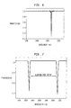
- Fig. 1 schematically illustrates a conventional optical fiber grating useful in understanding the problem to which the invention is directed.
- the grating comprises a core 10 and a surrounding glass cladding 11.
- the core is typically doped silica and includes a plurality of index perturbations 12 periodically induced along its length by ultraviolet radiation.
- the index differential between the core and an index perturbation is typically on the order of 0.0001.
- a typical grating period is on the order of 531.9 nm and a typical grating length is 4 cm.
- Fig. 2 illustrates the transmission characteristic of the Fig. 1 device, showing the main Bragg resonance 20 and the short wavelength cladding loss resonances 21. It is noteworthy that the closely spaced cladding mode resonances begin only 3 nm short of the main Bragg resonance 20 and extend down beyond 1530 nm. These cladding mode losses limit the useful bandwidth of the Bragg filter.
- ⁇ m spacing between the m th and (m + 1 ) th cladding mode resonances can be approximated by: ⁇ m ⁇ ⁇ 2 o D 2 clad [1+2 m ] ⁇ Bragg
- ⁇ o is the wavelength
- n is the refractive index of the cladding
- D clad is the diameter of the cladding
- m is the order of the cladding mode resonance
- ⁇ Bragg is the period of the Bragg grating.
- wavelength spacing between the fundamental Bragg resonance and the first cladding mode resonance is given by: ⁇ 1 ⁇ ⁇ 2 o D 2 clad ⁇ Bragg
- ⁇ m and ⁇ 1 are inversely proportional to D 2 clad , both can be increased by decreasing the cladding diameter.
- a reduction in cladding diameter below that used for conventional transmission fiber substantially decreases the robustness of the fiber and makes it more susceptible to mechanical failure.
- Fig. 3 schematically illustrates the cross section of an improved optical fiber Bragg grating 9 in accordance with the invention.
- the cladding glass 11 is provided with a plurality of longitudinally extending internal gaps or voids 30 peripherally surrounding the core 10.
- the gaps are closely spaced to prevent light from passing between them.
- the gaps are spaced from the core and dimensioned to form a interior cladding about the core which is thin compared to the glass cladding, i.e. it provides a much smaller cladding diameter D clad.
- This increases the cladding mode spacing ⁇ m and the wavelength spacing ⁇ 1 between the Bragg resonance and the first cladding mode resonance (cladding mode offset).
- the interior cladding is sufficiently close to the core that the cladding mode offset is at least 20 nm and even more preferably 40 nm.
- the gaps 30 comprise holes of maximum cross-sectional dimension in the range 1-25 ⁇ max . They are disposed peripherally around the core at a distance of 2-10 ⁇ max from the core center. For a grating receiving 1.5 - 1.6 ⁇ m light, the gaps could be circles of diameter 1.5 - 37.5 ⁇ m disposed in a circular ring of radius 3.0 - 15 ⁇ m from the core center to the edge of the gaps.
- the gaps are spaced apart around the periphery of the core so that the thin silica webs 31 between them have a thickness less than ⁇ min and preferably less than 0.5 ⁇ min .
- the webs would have a thickness of less than 1.5 ⁇ m and preferably less than 0.75 ⁇ m.
- the fiber can be drawn from an appropriate fiber preform.
- Fig. 4 illustrates an arrangement for making such a preform.
- the preform is fabricated by taking a core rod 40 including a core region 41 and surrounding it by silica tubes 42 such that the tubes touch one another and all the tubes 42 touch the core rod 40.
- the easiest preform to make is when the tubes and core rod are of the same diameter. In this case it takes six tubes to surround the core rod, forming a close packed arrangement.
- the core rod can have any index profile desired and can be doped with any photosensitive elements. It can also but not necessarily include a cladding region 43.
- the core rod is made by standard MCVD techniques and then drawn to the appropriate diameter (typically around 1 mm in diameter).
- the tubes 42 are closed off at one end and then the tube-core-rod bundle is overclad by an overcladding tube 44 using standard overclad techniques.
- the preform is then drawn into fiber under standard conditions.
- the inner cladding consists of the silica from the core rod (if any is present) and from the thickness of the walls of silica tubes 42.
- Bragg gratings are written in the core by ultraviolet radiation in the conventional manner.
- the air gaps 30 can optionally be filled with lossy polymers or reflective material.
- Suitable polymers include fluorinated polymers such as fluoroacrylates and fluoromethacrylates and their copolymers with hydrogen-based acrylates, fluorinated urethanes and silicon-based polymers such as siloxanes.
- fluorine-containing polymers the refractive index can be adjusted by changing the fluorine content in the polymer molecule.
- siloxanes the refractive index is adjusted by changing the ratio of methyl to phenyl groups attached to the siloxane chain.
- the polymers can be infused into the airgaps 30 by vacuum assisted capillary action.
- Suitable reflectors include metals such as gold, indium, aluminum and nickel. They provide a barrier through which the cladding modes cannot tunnel.
- the region within the peripheral gaps 30 will be smaller or larger than the core of a fiber to which the device is to be joined.
- the two different fibers should be joined by an adiabatic taper section. It is also possible to taper the air-gaps 30, in effect tapering the waveguide adiabatically, and thereby allowing a large mode in conventional fiber to match well to the fiber of the improved grating.
- Fig. 5 shows a schematic cross section of the central region of the high-delta microstructured fiber designed to reduce cladding mode loss in a fiber Bragg grating ("FBG").
- FBG fiber Bragg grating
- Approximately 2 ⁇ m from the center of the core 10 are five air-holes 30 approximately 7 ⁇ m in diameter.
- the outer silica cladding (not shown) extends to a diameter of 175 ⁇ m.
- the air-holes are exploited to directly manipulate the core mode as well as to isolate the cladding modes from the central core region and only a single layer of air-holes is required for guidance.
- the transmission spectrum of the Fig. 5 device is shown in Fig. 6.
- the resonant wavelength occurs at approximately 1505 nm.
- the effective index of the core mode is approximately n eff ⁇ 1.40, which is well below that of silica.
- the low effective index of the core mode is due to the strong overlap of the core mode with the closely spaced air-holes, and is indicative of the significant waveguide contribution to the dispersion of this fiber.
- Fig. 6 the absence of cladding mode loss for this range of wavelengths. Because of the small effective inner cladding diameter of this fiber, the cladding modes are offset significantly from the Bragg resonance.
- the fiber was modeled using beam-propagation method simulation software where the central region was considered surrounded by infinite silica cladding.
- the corresponding cladding mode spectrum in this fiber is offset from the Bragg resonance by as much as 80 nm, consistent with the measured grating spectra.
- Further simulations of the entire fiber structure indicate that the core guided mode is not the fundamental mode of the fiber, that is there exist cladding modes with energy in the outer cladding region that have propagation constants higher than the core mode.
- These cladding modes (with n eff > n core ) have negligible spatial overlap with the grating in the central core region and thus are not excited by interaction of core guided light with the grating.
- grating scattered light is confined within the core region due to total internal reflection off of the inner air-silica boundary.
- the improved gratings can be unchirped or chirped and fixed in Bragg resonance or tunable. They can be unchirped with nearly identical spacings between perturbations to reflect a narrow band of wavelengths. Alternatively they can be chirped with varying spacing between perturbations to reflect a broader band of wavelengths. See United States Patent No. 5,694,248, issued to T. Bach et al . on which is incorporated herein by reference. In chirped form the gratings can also be used as dispersion compensators. The improved gratings can be fixed in wavelength or they can be tunable by the application of strain or heat. See EP-A-1024391.
- FIG. 8 schematically illustrates a simplified communication system 80 using the improved gratings 9 for add/drop filtering.
- the system 80 comprises a transmitter 81, a receiver 84 and an add/drop filter 82 comprising an optical circulator 83 and one or more improved gratings 9(a) - 9(c).
- the gratings are typically unchirped. If the transmitter transmits four wavelengths ⁇ 1 - ⁇ 4 and the gratings 9(a) - 9(c) reflect wavelengths ⁇ 1 - ⁇ 3 , respectively, then ⁇ 4 will be dropped from the transmitted signal. If broadband or tunable gratings are used, then the number of gratings 9 can be reduced.
- the improved gratings are particularly useful in such cascaded or broadband filters as short wavelength loss is a problem with them.
- Fig. 9 schematically illustrates a simplified communication system 90 employing a dispersion compensating module using the improved gratings.
- the system comprises a transmitter 91, a receiver 94 and the module 92.
- the module 92 comprises an optical circulator 93 and one or more improved gratings 9(a) - 9(c) for dispersion compensation.
- the gratings are chirped and preferably tunable.
- the order in which the gratings may be placed in the module depends on the chromatic dispersion that has accumulated in the system before reaching the module. For example, if the accumulated dispersion for channel ⁇ 1 is greater than that for channel ⁇ 3 , then the gratings are arranged in the order shown, i.e.
- the first compensating grating is at ⁇ 1 and the last is at ⁇ 3 . If the accumulated dispersion for the channel at ⁇ 1 is less than that for ⁇ 3 , then the gratings should be arranged in the reverse order.
- a single broadband tunable chirped grating can be used instead of a plurality of gratings 9(a) - 9(c).
Landscapes
- Physics & Mathematics (AREA)
- Optics & Photonics (AREA)
- General Physics & Mathematics (AREA)
- Chemical & Material Sciences (AREA)
- Engineering & Computer Science (AREA)
- Life Sciences & Earth Sciences (AREA)
- Crystallography & Structural Chemistry (AREA)
- General Life Sciences & Earth Sciences (AREA)
- Geochemistry & Mineralogy (AREA)
- Manufacturing & Machinery (AREA)
- Materials Engineering (AREA)
- Organic Chemistry (AREA)
- Diffracting Gratings Or Hologram Optical Elements (AREA)
- Optical Fibers, Optical Fiber Cores, And Optical Fiber Bundles (AREA)
Applications Claiming Priority (2)
| Application Number | Priority Date | Filing Date | Title |
|---|---|---|---|
| US519382 | 1990-05-04 | ||
| US09/519,382 US6415079B1 (en) | 2000-03-03 | 2000-03-03 | Optical fiber gratings having internal gap cladding for reduced short wavelength cladding mode loss |
Publications (2)
| Publication Number | Publication Date |
|---|---|
| EP1134598A2 true EP1134598A2 (de) | 2001-09-19 |
| EP1134598A3 EP1134598A3 (de) | 2004-01-21 |
Family
ID=24068068
Family Applications (1)
| Application Number | Title | Priority Date | Filing Date |
|---|---|---|---|
| EP01301451A Withdrawn EP1134598A3 (de) | 2000-03-03 | 2001-02-19 | Optische Fasergitter mit internen Hohlräumen im Fasermantel zur Verminderung der kurzwelligen Mantelmodenverluste |
Country Status (4)
| Country | Link |
|---|---|
| US (1) | US6415079B1 (de) |
| EP (1) | EP1134598A3 (de) |
| JP (1) | JP3745967B2 (de) |
| CA (1) | CA2331914A1 (de) |
Cited By (1)
| Publication number | Priority date | Publication date | Assignee | Title |
|---|---|---|---|---|
| EP1146357A3 (de) * | 2000-03-03 | 2004-05-06 | Lucent Technologies Inc. | Glasfasergitter, welches einen Polymermantel mit angepasstem Brechungsindex zur Mantelmodenunterdrückung beinhaltet |
Families Citing this family (17)
| Publication number | Priority date | Publication date | Assignee | Title |
|---|---|---|---|---|
| FR2811437A1 (fr) * | 2000-07-06 | 2002-01-11 | Cit Alcatel | Fibre optique a pompage par la gaine et procede de fabrication d'une telle fibre |
| CN1539090A (zh) * | 2001-04-12 | 2004-10-20 | �ź㴫 | 高折射率差纤维波导及其应用 |
| US6671434B2 (en) * | 2001-04-17 | 2003-12-30 | Jds Uniphase Corporation | Optical performance monitor |
| WO2003010578A1 (en) * | 2001-07-12 | 2003-02-06 | Ocg Technology Licensing, Llc | Optical fiber |
| US6839481B2 (en) * | 2003-04-04 | 2005-01-04 | Fitel Usa Corp. | High-capacity multimode optical fiber systems |
| US7440664B2 (en) * | 2003-04-08 | 2008-10-21 | Fitel Usa Corp. | Microstructured optical waveguide for providing periodic and resonant structures |
| CA2575526A1 (en) * | 2004-08-25 | 2006-03-02 | Koheras A/S | A method of inducing refractive index structures in a micro-structured fiber, a micro-structured fiber and an article |
| US7587110B2 (en) * | 2005-03-22 | 2009-09-08 | Panasonic Corporation | Multicore optical fiber with integral diffractive elements machined by ultrafast laser direct writing |
| CN102317825A (zh) | 2008-12-18 | 2012-01-11 | 手性光子公司 | 光纤衍射光栅 |
| RU2437129C1 (ru) | 2010-03-24 | 2011-12-20 | Закрытое акционерное общество "Профотек" | Способ изготовления двулучепреломляющего микроструктурного оптического волокна |
| WO2017176825A1 (en) | 2016-04-08 | 2017-10-12 | Corning Optical Communications LLC | Traceable end point cable assembly |
| US10107983B2 (en) * | 2016-04-29 | 2018-10-23 | Corning Optical Communications LLC | Preferential mode coupling for enhanced traceable patch cord performance |
| US10622778B2 (en) * | 2017-04-05 | 2020-04-14 | National Chung Shan Institute Of Science And Technolgy | High-power fiber cladding power stripper |
| WO2020118550A1 (zh) * | 2018-12-12 | 2020-06-18 | 华为技术有限公司 | 一种介质传输线及网络设备 |
| CN113281832B (zh) * | 2020-02-19 | 2024-12-17 | 天津大学 | 光片生成器、光纤以及成像系统 |
| US11901691B2 (en) * | 2020-03-18 | 2024-02-13 | Lumentum Operations Llc | Subsurface induced scattering centers |
| CN113109899B (zh) * | 2021-03-31 | 2021-11-16 | 威海长和光导科技有限公司 | 一种光子晶体光纤及其制备方法 |
Family Cites Families (10)
| Publication number | Priority date | Publication date | Assignee | Title |
|---|---|---|---|---|
| US5155792A (en) * | 1991-06-27 | 1992-10-13 | Hughes Aircraft Company | Low index of refraction optical fiber with tubular core and/or cladding |
| US6236782B1 (en) * | 1995-08-29 | 2001-05-22 | Arroyo Optics, Inc. | Grating assisted coupler devices |
| US5907665A (en) | 1995-10-11 | 1999-05-25 | Hewlett-Packard Company | Method and apparatus for transforming image data |
| US5802236A (en) * | 1997-02-14 | 1998-09-01 | Lucent Technologies Inc. | Article comprising a micro-structured optical fiber, and method of making such fiber |
| US6169830B1 (en) * | 1996-08-26 | 2001-01-02 | Arroyo Optics, Inc. | Methods of fabricating grating assisted coupler devices |
| US6266463B1 (en) * | 1997-06-18 | 2001-07-24 | Pirelli Cavi E Sistemi S.P.A. | Chirped optical fibre grating |
| GB9713422D0 (en) * | 1997-06-26 | 1997-08-27 | Secr Defence | Single mode optical fibre |
| US5907652A (en) * | 1997-09-11 | 1999-05-25 | Lucent Technologies Inc. | Article comprising an air-clad optical fiber |
| JPH11237514A (ja) * | 1998-02-20 | 1999-08-31 | Shin Etsu Chem Co Ltd | グレーティング用光ファイバ、グレーティング用光ファイバ母材およびその光ファイバ母材の製造方法 |
| US6169831B1 (en) * | 1998-09-23 | 2001-01-02 | Lucent Technologies Inc. | Method of making optical chirped grating with an intrinsically chirped grating and external gradient |
-
2000
- 2000-03-03 US US09/519,382 patent/US6415079B1/en not_active Expired - Fee Related
-
2001
- 2001-01-23 CA CA002331914A patent/CA2331914A1/en not_active Abandoned
- 2001-02-19 EP EP01301451A patent/EP1134598A3/de not_active Withdrawn
- 2001-03-02 JP JP2001057528A patent/JP3745967B2/ja not_active Expired - Fee Related
Cited By (1)
| Publication number | Priority date | Publication date | Assignee | Title |
|---|---|---|---|---|
| EP1146357A3 (de) * | 2000-03-03 | 2004-05-06 | Lucent Technologies Inc. | Glasfasergitter, welches einen Polymermantel mit angepasstem Brechungsindex zur Mantelmodenunterdrückung beinhaltet |
Also Published As
| Publication number | Publication date |
|---|---|
| US6415079B1 (en) | 2002-07-02 |
| JP3745967B2 (ja) | 2006-02-15 |
| EP1134598A3 (de) | 2004-01-21 |
| CA2331914A1 (en) | 2001-09-03 |
| JP2001290035A (ja) | 2001-10-19 |
Similar Documents
| Publication | Publication Date | Title |
|---|---|---|
| US6415079B1 (en) | Optical fiber gratings having internal gap cladding for reduced short wavelength cladding mode loss | |
| US6445862B1 (en) | Dispersion compensating photonic crystal fiber | |
| US6418258B1 (en) | Microstructured optical fiber with improved transmission efficiency and durability | |
| US9671553B2 (en) | Bend-resistant multimode optical fiber | |
| AU711424B2 (en) | Wavelength selective grating assisted optical couplers | |
| US8280213B2 (en) | High-bandwidth multimode optical fiber with reduced cladding effect | |
| Stegall et al. | Dispersion control with use of long-period fiber gratings | |
| US8406593B2 (en) | Multimode optical fiber with low bending losses and reduced cladding effect | |
| US9014525B2 (en) | Trench-assisted multimode optical fiber | |
| US8483535B2 (en) | High-bandwidth, dual-trench-assisted multimode optical fiber | |
| US6301420B1 (en) | Multicore optical fibre | |
| US8520993B2 (en) | Multimode optical fiber having improved bending losses | |
| US8565568B2 (en) | Broad-bandwidth multimode optical fiber having reduced bending losses | |
| US7292762B2 (en) | Hole-assisted holey fiber and low bending loss multimode holey fiber | |
| US7773846B2 (en) | Large effective area high SBS threshold optical fiber | |
| EP0866574B1 (de) | Dispersionskompensierte optische Faser und ein entsprechendes Übertragungssystem | |
| US20120275751A1 (en) | High-Bandwidth, Radiation-Resistant Multimode Optical Fiber | |
| WO2001059496A2 (en) | Dispersion compensating module and mode converter, coupler and dispersion compensating optical waveguide therein | |
| JP3504823B2 (ja) | 光ファイバ通信システム | |
| Keiser | Optical signal attenuation and dispersion | |
| EP1788415A1 (de) | Loch-unterstützte mikrostrukturierte faser und mikrostrukturierte multimodus-faser mit geringem krümmungsverlust | |
| Goel et al. | Fiber Bragg Grating in an Antiresonant Hollow-Core Fiber | |
| Bise et al. | Temperature tuning of dispersion in a photonic band gap fiber | |
| Tsuchida et al. | Comparison of microbending loss characteristics between LMA holey fibers and conventional LMA fibers | |
| SAITOH et al. | A design method for bending-insensitive single-mode holey fibers |
Legal Events
| Date | Code | Title | Description |
|---|---|---|---|
| PUAI | Public reference made under article 153(3) epc to a published international application that has entered the european phase |
Free format text: ORIGINAL CODE: 0009012 |
|
| AK | Designated contracting states |
Kind code of ref document: A2 Designated state(s): AT BE CH CY DE DK ES FI FR GB GR IE IT LI LU MC NL PT SE TR |
|
| AX | Request for extension of the european patent |
Free format text: AL;LT;LV;MK;RO;SI |
|
| PUAL | Search report despatched |
Free format text: ORIGINAL CODE: 0009013 |
|
| RIC1 | Information provided on ipc code assigned before grant |
Ipc: 7G 02B 6/22 B Ipc: 7C 03B 37/012 B Ipc: 7G 02B 6/16 B Ipc: 7G 02B 6/293 A |
|
| AK | Designated contracting states |
Kind code of ref document: A3 Designated state(s): AT BE CH CY DE DK ES FI FR GB GR IE IT LI LU MC NL PT SE TR |
|
| AX | Request for extension of the european patent |
Extension state: AL LT LV MK RO SI |
|
| 17P | Request for examination filed |
Effective date: 20040227 |
|
| 17Q | First examination report despatched |
Effective date: 20040823 |
|
| AKX | Designation fees paid |
Designated state(s): DE FI GB IT |
|
| GRAP | Despatch of communication of intention to grant a patent |
Free format text: ORIGINAL CODE: EPIDOSNIGR1 |
|
| GRAS | Grant fee paid |
Free format text: ORIGINAL CODE: EPIDOSNIGR3 |
|
| STAA | Information on the status of an ep patent application or granted ep patent |
Free format text: STATUS: THE APPLICATION IS DEEMED TO BE WITHDRAWN |
|
| 18D | Application deemed to be withdrawn |
Effective date: 20051018 |