EP1134849B1 - Jeu de pièces d'éclairage pour l'éclairage, l'affichage ou la signalisation et connecteur électrique pour un tel jeu de pièces - Google Patents
Jeu de pièces d'éclairage pour l'éclairage, l'affichage ou la signalisation et connecteur électrique pour un tel jeu de pièces Download PDFInfo
- Publication number
- EP1134849B1 EP1134849B1 EP01103724A EP01103724A EP1134849B1 EP 1134849 B1 EP1134849 B1 EP 1134849B1 EP 01103724 A EP01103724 A EP 01103724A EP 01103724 A EP01103724 A EP 01103724A EP 1134849 B1 EP1134849 B1 EP 1134849B1
- Authority
- EP
- European Patent Office
- Prior art keywords
- contact
- module
- modules
- kit according
- connector
- Prior art date
- Legal status (The legal status is an assumption and is not a legal conclusion. Google has not performed a legal analysis and makes no representation as to the accuracy of the status listed.)
- Expired - Lifetime
Links
Images



Classifications
-
- F—MECHANICAL ENGINEERING; LIGHTING; HEATING; WEAPONS; BLASTING
- F21—LIGHTING
- F21S—NON-PORTABLE LIGHTING DEVICES; SYSTEMS THEREOF; VEHICLE LIGHTING DEVICES SPECIALLY ADAPTED FOR VEHICLE EXTERIORS
- F21S2/00—Systems of lighting devices, not provided for in main groups F21S4/00 - F21S10/00 or F21S19/00, e.g. of modular construction
- F21S2/005—Systems of lighting devices, not provided for in main groups F21S4/00 - F21S10/00 or F21S19/00, e.g. of modular construction of modular construction
-
- F—MECHANICAL ENGINEERING; LIGHTING; HEATING; WEAPONS; BLASTING
- F21—LIGHTING
- F21V—FUNCTIONAL FEATURES OR DETAILS OF LIGHTING DEVICES OR SYSTEMS THEREOF; STRUCTURAL COMBINATIONS OF LIGHTING DEVICES WITH OTHER ARTICLES, NOT OTHERWISE PROVIDED FOR
- F21V21/00—Supporting, suspending, or attaching arrangements for lighting devices; Hand grips
- F21V21/005—Supporting, suspending, or attaching arrangements for lighting devices; Hand grips for several lighting devices in an end-to-end arrangement, i.e. light tracks
-
- F—MECHANICAL ENGINEERING; LIGHTING; HEATING; WEAPONS; BLASTING
- F21—LIGHTING
- F21V—FUNCTIONAL FEATURES OR DETAILS OF LIGHTING DEVICES OR SYSTEMS THEREOF; STRUCTURAL COMBINATIONS OF LIGHTING DEVICES WITH OTHER ARTICLES, NOT OTHERWISE PROVIDED FOR
- F21V23/00—Arrangement of electric circuit elements in or on lighting devices
- F21V23/06—Arrangement of electric circuit elements in or on lighting devices the elements being coupling devices, e.g. connectors
-
- H—ELECTRICITY
- H01—ELECTRIC ELEMENTS
- H01R—ELECTRICALLY-CONDUCTIVE CONNECTIONS; STRUCTURAL ASSOCIATIONS OF A PLURALITY OF MUTUALLY-INSULATED ELECTRICAL CONNECTING ELEMENTS; COUPLING DEVICES; CURRENT COLLECTORS
- H01R13/00—Details of coupling devices of the kinds covered by groups H01R12/70 or H01R24/00 - H01R33/00
- H01R13/40—Securing contact members in or to a base or case; Insulating of contact members
- H01R13/405—Securing in non-demountable manner, e.g. moulding, riveting
- H01R13/41—Securing in non-demountable manner, e.g. moulding, riveting by frictional grip in grommet, panel or base
-
- H—ELECTRICITY
- H01—ELECTRIC ELEMENTS
- H01R—ELECTRICALLY-CONDUCTIVE CONNECTIONS; STRUCTURAL ASSOCIATIONS OF A PLURALITY OF MUTUALLY-INSULATED ELECTRICAL CONNECTING ELEMENTS; COUPLING DEVICES; CURRENT COLLECTORS
- H01R13/00—Details of coupling devices of the kinds covered by groups H01R12/70 or H01R24/00 - H01R33/00
- H01R13/46—Bases; Cases
- H01R13/514—Bases; Cases composed as a modular blocks or assembly, i.e. composed of co-operating parts provided with contact members or holding contact members between them
-
- H—ELECTRICITY
- H10—SEMICONDUCTOR DEVICES; ELECTRIC SOLID-STATE DEVICES NOT OTHERWISE PROVIDED FOR
- H10W—GENERIC PACKAGES, INTERCONNECTIONS, CONNECTORS OR OTHER CONSTRUCTIONAL DETAILS OF DEVICES COVERED BY CLASS H10
- H10W90/00—Package configurations
-
- F—MECHANICAL ENGINEERING; LIGHTING; HEATING; WEAPONS; BLASTING
- F21—LIGHTING
- F21Y—INDEXING SCHEME ASSOCIATED WITH SUBCLASSES F21K, F21L, F21S and F21V, RELATING TO THE FORM OR THE KIND OF THE LIGHT SOURCES OR OF THE COLOUR OF THE LIGHT EMITTED
- F21Y2105/00—Planar light sources
- F21Y2105/10—Planar light sources comprising a two-dimensional [2D] array of point-like light-generating elements
-
- F—MECHANICAL ENGINEERING; LIGHTING; HEATING; WEAPONS; BLASTING
- F21—LIGHTING
- F21Y—INDEXING SCHEME ASSOCIATED WITH SUBCLASSES F21K, F21L, F21S and F21V, RELATING TO THE FORM OR THE KIND OF THE LIGHT SOURCES OR OF THE COLOUR OF THE LIGHT EMITTED
- F21Y2115/00—Light-generating elements of semiconductor light sources
- F21Y2115/10—Light-emitting diodes [LED]
-
- H—ELECTRICITY
- H01—ELECTRIC ELEMENTS
- H01R—ELECTRICALLY-CONDUCTIVE CONNECTIONS; STRUCTURAL ASSOCIATIONS OF A PLURALITY OF MUTUALLY-INSULATED ELECTRICAL CONNECTING ELEMENTS; COUPLING DEVICES; CURRENT COLLECTORS
- H01R9/00—Structural associations of a plurality of mutually-insulated electrical connecting elements, e.g. terminal strips or terminal blocks; Terminals or binding posts mounted upon a base or in a case; Bases therefor
- H01R9/22—Bases, e.g. strip, block, panel
- H01R9/24—Terminal blocks
-
- Y—GENERAL TAGGING OF NEW TECHNOLOGICAL DEVELOPMENTS; GENERAL TAGGING OF CROSS-SECTIONAL TECHNOLOGIES SPANNING OVER SEVERAL SECTIONS OF THE IPC; TECHNICAL SUBJECTS COVERED BY FORMER USPC CROSS-REFERENCE ART COLLECTIONS [XRACs] AND DIGESTS
- Y10—TECHNICAL SUBJECTS COVERED BY FORMER USPC
- Y10S—TECHNICAL SUBJECTS COVERED BY FORMER USPC CROSS-REFERENCE ART COLLECTIONS [XRACs] AND DIGESTS
- Y10S362/00—Illumination
- Y10S362/80—Light emitting diode
Definitions
- the invention initially relates to an illumination kit for lighting, Display or notice purposes, including at least two identical, light-giving modules, each with at least one LED and the electronic components required to control them such as conductor tracks, resistors or the like. and with one each close to the edge contact zone set with at least two arranged on the module Contact zones of different potential for connection or tapping the voltage according to the preamble of claim 1. Further relates the invention relates to a connector for an illumination kit according to the preamble of claim 5.
- LED Light emission diodes
- the advantage of LED is particularly low in its energy consumption Heat emission, the high luminance and a compared to conventional Lamps much longer life.
- Multiple arrangements of LEDs are also used for lighting purposes as above all for display and information purposes.
- In reinforced Dimensions are tail lights, brake lights and turn signals Vehicles so equipped. Also leave advertising and information signs look great with such LEDs.
- the object of the invention is first of all an illumination kit the presupposed in the preamble of claim 1 as known Way to design and develop such that almost any Arrangement of at least two modules in the specified grid size to be able to build up particularly in terms of space.
- Another object of the invention is to provide a reliable one and to propose small connectors.
- the invention solves the first object with the features of the independent Claim 1 and accordingly characterized that the contact zones of each contact zone set along one Line are arranged that are substantially perpendicular to the adjacent Edge edge of the module is aligned and that for mechanical and electrical connection of two modules with each other on the Edge of each module is provided with pluggable connectors Contacts, which are all arranged in a row, the respective same distance from the transverse center plane of the connector having contacts are bridged.
- the essence of the invention is the contact zones each contact zone set of each module in a clever way to be arranged so that two modules each with a very simple designed connector, whose contacts do not cross must be electrically and mechanically connected can. That the contacts of the connector are all in a row Arranged also means that the contacts are the respective modules contact only from one side, resulting in an extremely flat Construction of the connector results.
- the Contact zones are plated through the circuit board of the module, so that the contacts of the connector select the contact zones can contact from one or the other side of the module. This makes it easy to e.g. possible using the connector two modules to be connected to it with different radiation directions to arrange their LED with reverse polarity protection.
- each contact zone set of the module is preferably a recess assigned to the preferably releasable Engagement of a locking pin of the connector, wherein it is in this Context is advantageous if the recess in the same Row is arranged like the contact zone of the module and the locking pin in the same row as the connector's contacts.
- the invention relates to a connector of a Illumination kit, according to the dependent claim 5 is characterized in that it has a contact carrier and a Contact set includes, the contact elements on one side of the contact carrier are attached to this.
- the contact elements are preferably flat and extend substantially parallel to the main plane of the plate-like flat contact carrier.
- Each contact element preferably forms a contact bridge for connecting the contact zones of the same potential of two modules out.
- each contact element a fastening section and attached to one Forms contact section, each substantially fork-shaped is formed and the fork leg of a contact element between the fork legs of another contact element in the same Level are arranged.
- the contact elements have notched anchor edges with which they form and / or plugged into the locking pin of the contact carrier are.
- the connector has a particularly plate-like Cover covers, between itself and the contacts of the contact carrier opposing slot receptacles for edge edges two modules to be connected.
- Contact carriers are preferred and cover with each other - releasable if necessary - lockable.
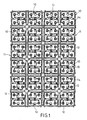
- Fig. 1 shows a multiple arrangement of mutually identical Modules 10.
- Each of these modules 10 comprises a printed circuit board 11, four LEDs 12 as well as resistors 13 and conductor tracks 14.
- the wiring is designed so that all boards 11 via conductor tracks are electrically connected to each other.
- the in the embodiment 1 a total of 96 LEDs of the 24 modules 10 could therefore illuminated at the same time when voltage is applied become.
- FIG. 2 shows a module in an enlarged representation compared to FIG. 1.
- those labeled 15 and 16 Contact zones, each with a positive pole (contact zone 15) and form a negative pole (contact zone 16), arranged on a line 17 are, at least to the associated edge 18 of the module 10 is substantially vertical.
- Both contact zones 15 and 16, which together form a contact zone set are arranged close to the edge.
- the plus pole 15 is outside and the Negative pole 16 arranged further inside on line 17.
- the exemplary embodiment shows a module 10 with a square outline with four SMD-LED 12.
- Other shapes are a matter of course also possible, e.g. would you with a module outline in the form of a regular hexagons get a honeycomb pattern, which is special would be suitable for an arrangement of three or six LEDs.
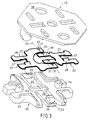
- the contact carrier 20 made of insulating material and two contact elements 21 and 22.
- the contact carrier 20 consists of one Plastic injection molding and essentially has a base plate 23 on and two locking cams 24 and two spring tongues 25 with locking pins 26th
- the locking pins 24 serve to firmly anchor the two Contact elements 21 and 22 on the contact carrier 20, which are used for this purpose are provided with anchor edges 27, which are made of the sheet metal material Contact elements 21 and 22 are released and issued. If the Contact elements 21 and 22 on the base plate 23 of the contact carrier 20 are pressed on, they are securely attached to it.
- the contact elements have 21 and 22 except for their fastening section including the anchor edges 27 28 each have a fork-shaped contact section 29 and 30 respectively.
- On The locking pins are the same line when the connector 19 is installed 26 arranged. They are used for positive engagement in Openings 34 in the circuit board 11 of each module 10 (FIG. 2).
- One only from a contact carrier 20 and the two contact elements 21 and 22 existing connector can by Pressure contact two modules electrically conductive and mechanically fixed connect with each other, provided e.g. on the device side, it is ensured that this connector firmly pressed onto the surfaces of the modules 10 and is held.
- cover 35 is provided. This includes a flat one Cover plate 36, the bottom with two pairs of locking hooks 37 and 38 with which it is fixed, i.e. producing a sufficient contact pressure, can be anchored to the contact carrier 20.
- Fig. 5 shows a connector 19 in the simple version without cover 35. Here you can see the locking of the extremely flat Contact elements 21 and 22 on the contact carrier 20 and you can see that the contacts 31 and 32 with the locking pin 26 all in a row 33 are arranged.
- each contact element 21 is an electrical bridge represents.
- the contact element 21 connects the two contact surfaces 16 of the modules 10 and the contact element 22 bridges the Contact areas 15 of the other potential.
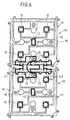
- FIG. 7 shows two modules 10 in a diagrammatic representation View of the component side and one coupling the two modules 10 Connector 19.
- the contact carrier is covered 20 of the connector 19, the contact elements.
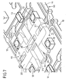
- the extremely flat design of the connector 19, whose contact carrier including those attached to it Flat contacts are essentially only as thick as an SMD LED 12 builds the board 11.
Landscapes
- Engineering & Computer Science (AREA)
- General Engineering & Computer Science (AREA)
- Coupling Device And Connection With Printed Circuit (AREA)
- Details Of Connecting Devices For Male And Female Coupling (AREA)
- Led Device Packages (AREA)
- Arrangement Of Elements, Cooling, Sealing, Or The Like Of Lighting Devices (AREA)
- Connector Housings Or Holding Contact Members (AREA)
Claims (12)
- Jeu de pièces d'éclairage pour l'éclairage, l'affichage ou la signalisation, comprenant au moins deux modules (10) dispensateurs de lumière, identiques, ayant chacun au moins une DEL (12) et les composants électroniques nécessaires à leur commande, tels que des pistes conductrices (14), des résistances (13) ou analogues, et ayant chacun un jeu de zones de contact (15/16) disposées près de la bordure sur le module (10), avec au moins deux zones de contact de potentiel différent pour le raccordement ou le prélèvement de la tension, caractérisé en ce que les zones de contact (15, 16) de chaque jeu de zones de contact (15/16) sont disposées suivant une ligne (17) orientée verticalement par rapport à l'arête de bordure voisine du module (10), et en ce que, pour assurer la liaison mécanique et électrique de deux modules (10) ensemble, est prévu une prise à enfichage (19) pouvant être enfichée sur le bord de chaque module (10), avec des contacts (31, 32) disposés globalement en une rangée (33), les contacts (31 ; 32), présentant chaque fois le même espacement vis-à-vis du plan médian transversal de la prise à enfichage (19), étant pontés.
- Jeu de pièces d'éclairage selon la revendication 1, caractérisé en ce que les zones de contact (15, 16) sont mises en contact par la plaque à circuit imprimé (11) du module (10) et de manière que les contacts (31, 32) de la prise à enfichage (19) puissent contacter les zones de contact (15 ; 16) à volonté, depuis l'une ou l'autre face du module (10).
- Jeu de pièces d'éclairage selon la revendication 1, caractérisé en ce qu'à chaque jeu de zones de contact (15/16) du module (10) est associé un évidement (34) pour l'engagement, de préférence redésolidarisable, d'un téton de verrouillage (26) de la prise à enfichage (19).
- Jeu de pièces d'éclairage selon la revendication 3, caractérisé en ce que l'évidement (34) est disposé dans la même rangée (17) que les zones de contact (15, 16) du module (10), et le téton de verrouillage (26) est disposé dans la même rangée (33) que les contacts (31, 32) de la prise à enfichage (19).
- Jeu de pièces d'éclairage selon l'une des revendications 1 à 4, caractérisé en ce que la prise à enfichage (19) comprend un support de contact (20) ainsi qu'un jeu de contact (31/32), dont les éléments de contact (21, 22) sont fixés, sur un côté du support de contact (20), sur celui-ci.
- Jeu de pièces d'éclairage selon la revendication 5, caractérisé en ce que les éléments de contact (21, 22) sont de configuration plate et s'étendent sensiblement parallèlement au plan principal du support de contact (20) plat, se présentant sous forme de plaque.
- Jeu de pièces d'éclairage selon la revendication 5 ou 6, caractérisé en ce que chaque élément de contact (21, 22) constitue un pont de contact pour la liaison des zones de contact (15 ; 16) du même potentiel de deux modules (20).
- Jeu de pièces d'éclairage selon la revendication 7, caractérisé en ce que chaque élément de contact (21, 22) constitue un tronçon de fixation (28) et, lié à celui-ci par la matière, un tronçon de contact (29 ; 30), qui est chaque fois réalisé sensiblement en fourche, et en ce que les dents de fourche d'un élément de contact (22) sont disposées entre les dents de fourche d'un autre élément de contact (21), dans le même plan.
- Jeu de pièces d'éclairage selon l'une des revendications 5 à 7, caractérisé en ce que les éléments de contact (21, 22) présentent des arêtes d'ancrage (27) pliées, à l'aide desquelles elles sont enfichées, par une liaison de forme et/ou de serrage, sur le téton d'encliquetage (24) du support de contact (20).
- Jeu de pièces d'éclairage selon la revendication 2 ainsi que l'une des revendications 5 à 9, caractérisé en ce que sont réalisées des languettes élastiques (25) découpées de façon libre sur le support de contact (20), aux extrémités desquelles sont disposés les tétons de verrouillage (26) conçus pour l'engagement dans les évidements (34) des modules (20).
- Jeu de pièces d'éclairage selon l'une des revendications 5 à 7, caractérisé en ce qu'il comprend en plus un couvercle (35), en particulier du genre d'une plaque, formant, entre lui et les contacts (31, 32) du support de contact (20), des logements en fente opposés les uns les autres pour les arêtes de bordure de deux modules (20) à relier.
- Jeu de pièces d'éclairage selon la revendication 11, caractérisé en ce que le support de contact (20) et le couvercle (35) sont encliquetables ensemble.
Applications Claiming Priority (2)
| Application Number | Priority Date | Filing Date | Title |
|---|---|---|---|
| DE10012734 | 2000-03-16 | ||
| DE10012734A DE10012734C1 (de) | 2000-03-16 | 2000-03-16 | Illuminationsbausatz für Beleuchtungs-, Anzeige- oder Hinweiszwecke sowie Steckverbinder für einen solchen Illuminationsbausatz |
Publications (2)
| Publication Number | Publication Date |
|---|---|
| EP1134849A1 EP1134849A1 (fr) | 2001-09-19 |
| EP1134849B1 true EP1134849B1 (fr) | 2003-05-02 |
Family
ID=7634890
Family Applications (1)
| Application Number | Title | Priority Date | Filing Date |
|---|---|---|---|
| EP01103724A Expired - Lifetime EP1134849B1 (fr) | 2000-03-16 | 2001-02-15 | Jeu de pièces d'éclairage pour l'éclairage, l'affichage ou la signalisation et connecteur électrique pour un tel jeu de pièces |
Country Status (6)
| Country | Link |
|---|---|
| US (1) | US6422716B2 (fr) |
| EP (1) | EP1134849B1 (fr) |
| JP (1) | JP4379762B2 (fr) |
| AT (1) | ATE239304T1 (fr) |
| DE (2) | DE10012734C1 (fr) |
| ES (1) | ES2197895T3 (fr) |
Families Citing this family (163)
| Publication number | Priority date | Publication date | Assignee | Title |
|---|---|---|---|---|
| DE10133255A1 (de) * | 2001-07-09 | 2003-01-30 | Osram Opto Semiconductors Gmbh | LED-Modul für Beleuchtungsvorrichtungen |
| JP2003036708A (ja) * | 2001-07-19 | 2003-02-07 | Ichikoh Ind Ltd | 自動車用ストップランプ |
| US7380961B2 (en) * | 2002-04-24 | 2008-06-03 | Moriyama Sangyo Kabushiki Kaisha | Light source coupler, illuminant device, patterned conductor, and method for manufacturing light source coupler |
| US20030218417A1 (en) * | 2002-05-22 | 2003-11-27 | Unity Opto Technology Co., Ltd. | Light emitting diode lamp with light emitting diode module having improved heat dissipation |
| US20030223210A1 (en) * | 2002-06-03 | 2003-12-04 | Yoon Chin | Modular LED circuit board |
| US7059754B2 (en) * | 2002-06-27 | 2006-06-13 | North American Lighting, Inc. | Apparatus and method for providing a modular vehicle light device |
| DE10242292A1 (de) * | 2002-09-12 | 2004-04-01 | Sebastian Matthias | Flächenlampe |
| KR100674786B1 (ko) * | 2002-10-25 | 2007-01-25 | 모리야마 산교 가부시키가이샤 | 발광 모듈 |
| TW570301U (en) * | 2003-02-13 | 2004-01-01 | Shang-Hua You | Adhesive type LED lead frame |
| FR2853392B1 (fr) * | 2003-04-04 | 2006-06-16 | Sli Miniature Lighting Sa | Feu arriere, en particulier feu stop pour vehicule automobile |
| USD507246S1 (en) * | 2003-04-10 | 2005-07-12 | Harvatek Corporation | Light emitting diode package |
| USD507544S1 (en) * | 2003-04-25 | 2005-07-19 | Harvatek Corporation | Light emitting diode package |
| AU2003902073A0 (en) * | 2003-05-01 | 2003-05-15 | Kevin Raymond Deguara | A lighting substrate |
| WO2004114736A2 (fr) * | 2003-06-20 | 2004-12-29 | Yazaki Corporation | Dispositif d'eclairage a diodes electroluminescentes |
| US7080927B2 (en) * | 2003-07-09 | 2006-07-25 | Stephen Feuerborn | Modular lighting with blocks |
| DE20311557U1 (de) | 2003-07-26 | 2003-10-16 | Neuhorst Paul Heinrich | Leuchte für Beleuchtungszwecke |
| DE10339417A1 (de) * | 2003-08-27 | 2005-04-14 | Hella Kgaa Hueck & Co. | Fahrzeugleuchte |
| USD505663S1 (en) * | 2004-01-21 | 2005-05-31 | Moriyama Sangyo Kabushiki Kaisha | LED holder |
| USD508234S1 (en) * | 2004-01-21 | 2005-08-09 | Moriyama Sangyo Kabushiki Kaisha | LED holder |
| USD505662S1 (en) * | 2004-01-21 | 2005-05-31 | Moriyama Sangyo Kabushiki Kaisha | LED holder |
| WO2005089293A2 (fr) * | 2004-03-15 | 2005-09-29 | Color Kinetics Incorporated | Procédés et systèmes pour la fourniture de systèmes d'éclairage |
| FR2870083B1 (fr) * | 2004-05-10 | 2006-07-14 | Sli Miniature Lighting Sa Sa | Dispositif de maintien et de connexion de composants optoelectroniques comme les leds du type plcc2 et plcc4 |
| USD509809S1 (en) * | 2004-08-10 | 2005-09-20 | Harvatek Corporation | Metal base design for surface mount device LED |
| CA2554010A1 (fr) * | 2004-10-08 | 2006-04-20 | Tempo Industries, Inc. | Systeme et procede d'eclairage par radiance |
| USD506187S1 (en) * | 2004-10-12 | 2005-06-14 | Harvatek Corporation | Metal base design for surface mount device LED (light emitting diode) |
| TWD110150S1 (zh) * | 2004-10-14 | 2006-04-11 | 東芝照明技術股份有限公司 | 照明用發光體 |
| TWD110149S1 (zh) * | 2004-10-14 | 2006-04-11 | 東芝照明技術股份有限公司 | 照明用發光體 |
| TWD110201S1 (zh) * | 2004-10-14 | 2006-04-11 | 東芝照明技術股份有限公司 | 照明用發光體 |
| TWD110148S1 (zh) * | 2004-10-14 | 2006-04-11 | 東芝照明技術股份有限公司 | 照明用發光體 |
| TWD110202S1 (zh) * | 2004-10-14 | 2006-04-11 | 東芝照明技術股份有限公司 | 照明用發光體 |
| TWD110200S1 (zh) * | 2004-10-14 | 2006-04-11 | 東芝照明技術股份有限公司 | 照明用發光體 |
| USD536309S1 (en) * | 2004-12-08 | 2007-02-06 | Nichia Corporation | Light emitting diode board |
| JP4583956B2 (ja) * | 2005-02-10 | 2010-11-17 | Necライティング株式会社 | 面状光源装置の製造方法 |
| TWD113253S1 (zh) * | 2005-02-28 | 2006-10-01 | 東芝照明技術股份有限公司 | 照明用發光二極體燈 |
| USD550869S1 (en) * | 2005-03-31 | 2007-09-11 | Moriyama Sangyo Kabushiki Kaisha | LED lamp |
| USD546985S1 (en) * | 2005-03-31 | 2007-07-17 | Moriyama Sangyo Kabushiki Kaisha | LED lamp |
| JP4548219B2 (ja) * | 2005-05-25 | 2010-09-22 | パナソニック電工株式会社 | 電子部品用ソケット |
| TWD120106S1 (zh) * | 2005-06-08 | 2007-11-21 | 松下電器產業股份有限公司 | 照明用發光元件模組 |
| USD535262S1 (en) * | 2005-06-08 | 2007-01-16 | Matsushita Electric Industrial Co., Ltd. | Light emitting diode module |
| TWD122880S1 (zh) * | 2005-06-08 | 2008-05-11 | 松下電器產業股份有限公司 | 照明用發光元件模組 |
| TWD120846S1 (zh) * | 2005-06-08 | 2008-01-01 | 松下電器產業股份有限公司 | 照明用發光元件模組 |
| ATE533666T1 (de) * | 2005-08-31 | 2011-12-15 | Delphi Tech Inc | System und methode zur bereitstellung von beleuchtung |
| TWD116536S1 (zh) * | 2005-09-16 | 2007-04-21 | 東芝照明技術股份有限公司 | 照明用發光體 |
| JP4623735B2 (ja) * | 2005-12-08 | 2011-02-02 | Smk株式会社 | コネクタ |
| DE602006020486D1 (de) * | 2005-12-16 | 2011-04-14 | Koninkl Philips Electronics Nv | Miteinander verbindbare beleuchtungsmodule umfassendes beleuchtungssystem |
| KR100659700B1 (ko) | 2005-12-30 | 2006-12-21 | 서울반도체 주식회사 | 연결단자가 내장된 발광소자 |
| US9335006B2 (en) * | 2006-04-18 | 2016-05-10 | Cree, Inc. | Saturated yellow phosphor converted LED and blue converted red LED |
| TWI306677B (en) * | 2006-09-14 | 2009-02-21 | Ind Tech Res Inst | Light emitting apparatus and screen |
| US9341328B2 (en) * | 2006-09-27 | 2016-05-17 | Osram Gesellschaft Mit Beschrankter Haftung | Method of producing a light emitting diode arrangement and light emitting diode arrangement |
| DE102007003809B4 (de) * | 2006-09-27 | 2012-03-08 | Osram Ag | Verfahren zum Herstellen einer Leuchtdiodenanordnung und Leuchtdiodenanordnung mit einer Mehrzahl von kettenförmig angeordneten LED-Modulen |
| US20080141571A1 (en) * | 2006-10-30 | 2008-06-19 | Hi*Tech Electronic Displays, Inc. | Modular interlocking graphics display panel |
| US20080141572A1 (en) * | 2006-10-30 | 2008-06-19 | Hi*Tech Electronic Displays, Inc. | Front and back serviceable modular interlocking graphics display panel |
| US10295147B2 (en) * | 2006-11-09 | 2019-05-21 | Cree, Inc. | LED array and method for fabricating same |
| US7897980B2 (en) * | 2006-11-09 | 2011-03-01 | Cree, Inc. | Expandable LED array interconnect |
| KR20080051499A (ko) * | 2006-12-06 | 2008-06-11 | 삼성전자주식회사 | 광원모듈 및 이를 갖는 표시장치 |
| KR100872696B1 (ko) * | 2007-04-16 | 2008-12-10 | 엘지이노텍 주식회사 | 광원 장치 및 이를 이용한 디스플레이 장치 |
| US7896521B2 (en) | 2007-05-04 | 2011-03-01 | Abl Ip Holding Llc | Adjustable light distribution system |
| EP2000736A1 (fr) * | 2007-06-05 | 2008-12-10 | Alcan Technology & Management Ltd. | Dispositif d'éclairage plat |
| WO2008157723A1 (fr) | 2007-06-21 | 2008-12-24 | Nila Inc. | Ensembles d'éclairage modulaires |
| US20090065797A1 (en) * | 2007-08-29 | 2009-03-12 | Lg Electronics Inc. | Light emitting unit and liquid crystal display device using the same |
| DE102007041136A1 (de) * | 2007-08-30 | 2009-03-05 | Osram Opto Semiconductors Gmbh | LED-Gehäuse |
| DE102007044566A1 (de) * | 2007-09-07 | 2009-03-12 | Arnold & Richter Cine Technik Gmbh & Co. Betriebs Kg | Beleuchtungssystem |
| CN101430066A (zh) * | 2007-11-06 | 2009-05-13 | 富士迈半导体精密工业(上海)有限公司 | 半导体固态光源模块及半导体固态光源模组 |
| KR101395059B1 (ko) * | 2007-11-29 | 2014-05-14 | 삼성디스플레이 주식회사 | 백라이트 유닛 및 이를 포함한 액정 표시 장치 |
| US8118447B2 (en) | 2007-12-20 | 2012-02-21 | Altair Engineering, Inc. | LED lighting apparatus with swivel connection |
| US7712918B2 (en) | 2007-12-21 | 2010-05-11 | Altair Engineering , Inc. | Light distribution using a light emitting diode assembly |
| USD602449S1 (en) * | 2008-02-18 | 2009-10-20 | Alti-Electronics Co., Ltd | Illumination tool using the light emitting diode |
| USD609200S1 (en) * | 2008-02-18 | 2010-02-02 | Alti-Electronics Co., Ltd. | Illumination tool using the light emitting diode |
| CN101539278B (zh) * | 2008-03-19 | 2010-11-10 | 富准精密工业(深圳)有限公司 | 发光二极管组合 |
| US8585260B2 (en) * | 2008-05-05 | 2013-11-19 | Nuru Energy Design And Development | Modular illumination device with pedal generator |
| US8360599B2 (en) | 2008-05-23 | 2013-01-29 | Ilumisys, Inc. | Electric shock resistant L.E.D. based light |
| JP5391767B2 (ja) | 2008-05-30 | 2014-01-15 | 東芝ライテック株式会社 | 発光装置及び照明器具 |
| US7976196B2 (en) | 2008-07-09 | 2011-07-12 | Altair Engineering, Inc. | Method of forming LED-based light and resulting LED-based light |
| US7946729B2 (en) | 2008-07-31 | 2011-05-24 | Altair Engineering, Inc. | Fluorescent tube replacement having longitudinally oriented LEDs |
| TWM352640U (en) * | 2008-08-22 | 2009-03-11 | Depo Auto Parts Ind Co Ltd | Positioning and assembling structure for lamp with LED light source |
| JP5077693B2 (ja) * | 2008-08-28 | 2012-11-21 | 東芝ライテック株式会社 | 照明器具 |
| US8674626B2 (en) | 2008-09-02 | 2014-03-18 | Ilumisys, Inc. | LED lamp failure alerting system |
| US8256924B2 (en) | 2008-09-15 | 2012-09-04 | Ilumisys, Inc. | LED-based light having rapidly oscillating LEDs |
| CN101709857B (zh) * | 2008-09-16 | 2012-01-25 | 东芝照明技术株式会社 | 光源单元以及使用此光源单元的照明器具 |
| US7952114B2 (en) | 2008-09-23 | 2011-05-31 | Tyco Electronics Corporation | LED interconnect assembly |
| US8214084B2 (en) | 2008-10-24 | 2012-07-03 | Ilumisys, Inc. | Integration of LED lighting with building controls |
| US8653984B2 (en) | 2008-10-24 | 2014-02-18 | Ilumisys, Inc. | Integration of LED lighting control with emergency notification systems |
| US7938562B2 (en) | 2008-10-24 | 2011-05-10 | Altair Engineering, Inc. | Lighting including integral communication apparatus |
| US8324817B2 (en) | 2008-10-24 | 2012-12-04 | Ilumisys, Inc. | Light and light sensor |
| US8444292B2 (en) | 2008-10-24 | 2013-05-21 | Ilumisys, Inc. | End cap substitute for LED-based tube replacement light |
| US8901823B2 (en) | 2008-10-24 | 2014-12-02 | Ilumisys, Inc. | Light and light sensor |
| US8251543B2 (en) | 2008-11-22 | 2012-08-28 | Innovative Lighting, Inc. | Interior corner mounting module for rope light system |
| JP2010129227A (ja) * | 2008-11-25 | 2010-06-10 | Toshiba Lighting & Technology Corp | 埋込形照明装置 |
| US8556452B2 (en) | 2009-01-15 | 2013-10-15 | Ilumisys, Inc. | LED lens |
| US8362710B2 (en) | 2009-01-21 | 2013-01-29 | Ilumisys, Inc. | Direct AC-to-DC converter for passive component minimization and universal operation of LED arrays |
| US8664880B2 (en) | 2009-01-21 | 2014-03-04 | Ilumisys, Inc. | Ballast/line detection circuit for fluorescent replacement lamps |
| KR20100086881A (ko) * | 2009-01-23 | 2010-08-02 | 삼성전자주식회사 | 백라이트 어셈블리 및 이를 포함하는 표시 장치 |
| US8678612B2 (en) * | 2009-04-14 | 2014-03-25 | Phoseon Technology, Inc. | Modular light source |
| US8330381B2 (en) | 2009-05-14 | 2012-12-11 | Ilumisys, Inc. | Electronic circuit for DC conversion of fluorescent lighting ballast |
| US8299695B2 (en) | 2009-06-02 | 2012-10-30 | Ilumisys, Inc. | Screw-in LED bulb comprising a base having outwardly projecting nodes |
| CA2765200A1 (fr) | 2009-06-23 | 2011-01-13 | Altair Engineering, Inc. | Dispositif d'eclairage comprenant des del et un systeme de commande d'alimentation a decoupage |
| JP5366688B2 (ja) * | 2009-07-16 | 2013-12-11 | 日本航空電子工業株式会社 | ソケット、基板組立体及びそれを備える装置 |
| WO2011033433A1 (fr) | 2009-09-17 | 2011-03-24 | Koninklijke Philips Electronics N.V. | Module d'éclairage et dispositif électroluminescent |
| US20110069493A1 (en) * | 2009-09-24 | 2011-03-24 | Huan-Chang Huang | LED Assembly |
| EP2302298A1 (fr) * | 2009-09-25 | 2011-03-30 | Toshiba Lighting & Technology Corporation | Appareil d'éclairage |
| US8308320B2 (en) | 2009-11-12 | 2012-11-13 | Cooper Technologies Company | Light emitting diode modules with male/female features for end-to-end coupling |
| CN102639926B (zh) * | 2009-12-02 | 2014-12-24 | 夏普株式会社 | 照明装置和显示装置 |
| US8511851B2 (en) * | 2009-12-21 | 2013-08-20 | Cree, Inc. | High CRI adjustable color temperature lighting devices |
| US9177492B2 (en) * | 2010-01-25 | 2015-11-03 | Gt Biomescilt Light Limited | Flexible LED display screens |
| CN101846271A (zh) * | 2010-03-23 | 2010-09-29 | 邓涛 | 一种led模块和led显示装置 |
| WO2011119958A1 (fr) | 2010-03-26 | 2011-09-29 | Altair Engineering, Inc. | Lampe à del interne-externe |
| US8541958B2 (en) | 2010-03-26 | 2013-09-24 | Ilumisys, Inc. | LED light with thermoelectric generator |
| CA2794512A1 (fr) | 2010-03-26 | 2011-09-29 | Ilumisys, Inc. | Tube de lampe a del avec repartition lumineuse laterale double |
| US8616720B2 (en) | 2010-04-27 | 2013-12-31 | Cooper Technologies Company | Linkable linear light emitting diode system |
| WO2011139768A2 (fr) | 2010-04-28 | 2011-11-10 | Cooper Technologies Company | Module d'éclairage à linéaire à del |
| US8454193B2 (en) | 2010-07-08 | 2013-06-04 | Ilumisys, Inc. | Independent modules for LED fluorescent light tube replacement |
| US8596813B2 (en) | 2010-07-12 | 2013-12-03 | Ilumisys, Inc. | Circuit board mount for LED light tube |
| DE102010039956A1 (de) | 2010-08-30 | 2012-03-01 | Osram Opto Semiconductors Gmbh | Lichtquellenvorrichtung und Lichtquellenanordnung |
| EP2614301A1 (fr) * | 2010-09-10 | 2013-07-17 | Robe Lighting, Inc | Carte de circuit imprimé pour luminaire à del |
| EP2633227B1 (fr) | 2010-10-29 | 2018-08-29 | iLumisys, Inc. | Mécanismes pour réduire le risque d'électrocution pendant l'installation d'un tube fluorescent |
| US9899329B2 (en) | 2010-11-23 | 2018-02-20 | X-Celeprint Limited | Interconnection structures and methods for transfer-printed integrated circuit elements with improved interconnection alignment tolerance |
| US8870415B2 (en) | 2010-12-09 | 2014-10-28 | Ilumisys, Inc. | LED fluorescent tube replacement light with reduced shock hazard |
| US9285089B2 (en) * | 2010-12-21 | 2016-03-15 | Bridgelux, Inc. | Automatic electrical connection assembly for light modules |
| US9786811B2 (en) | 2011-02-04 | 2017-10-10 | Cree, Inc. | Tilted emission LED array |
| US8934259B2 (en) | 2011-06-08 | 2015-01-13 | Semprius, Inc. | Substrates with transferable chiplets |
| USD700584S1 (en) | 2011-07-06 | 2014-03-04 | Cree, Inc. | LED component |
| US10842016B2 (en) | 2011-07-06 | 2020-11-17 | Cree, Inc. | Compact optically efficient solid state light source with integrated thermal management |
| KR101827717B1 (ko) * | 2011-07-08 | 2018-02-09 | 엘지이노텍 주식회사 | 조명 장치 |
| US8322906B2 (en) | 2011-08-08 | 2012-12-04 | XtraLight Manufacturing Partnership Ltd | Versatile lighting units |
| US9072171B2 (en) | 2011-08-24 | 2015-06-30 | Ilumisys, Inc. | Circuit board mount for LED light |
| DE102011056570A1 (de) | 2011-12-16 | 2013-06-20 | Osram Opto Semiconductors Gmbh | Lichtemittierende Bauelement-Anordnung |
| WO2013131002A1 (fr) | 2012-03-02 | 2013-09-06 | Ilumisys, Inc. | Embase de connecteur électrique pour lampe à base de del |
| US20130294078A1 (en) * | 2012-05-03 | 2013-11-07 | Chia-Tsung Tsao | Modular led illuminating device |
| DE102012208249A1 (de) | 2012-05-16 | 2013-11-21 | Osram Gmbh | Verbindungsmodul, Stromversorgungsmodul und Verbindungssatz für Leuchtbänder |
| EP2864696A4 (fr) * | 2012-06-26 | 2015-12-02 | Num Lighting Ltd | Système d'éclairage modulaire |
| WO2014008463A1 (fr) | 2012-07-06 | 2014-01-09 | Ilumisys, Inc. | Ensemble d'alimentation électrique pour tube lumineux à del |
| US9271367B2 (en) | 2012-07-09 | 2016-02-23 | Ilumisys, Inc. | System and method for controlling operation of an LED-based light |
| DE102012013963A1 (de) * | 2012-07-13 | 2014-01-16 | Ambright GmbH | Sensorleuchte |
| US8974077B2 (en) | 2012-07-30 | 2015-03-10 | Ultravision Technologies, Llc | Heat sink for LED light source |
| KR101301719B1 (ko) * | 2013-01-24 | 2013-09-10 | 주식회사 트루스타 | Led 램프용 전극모듈 |
| US9285084B2 (en) | 2013-03-14 | 2016-03-15 | Ilumisys, Inc. | Diffusers for LED-based lights |
| US20140268777A1 (en) * | 2013-03-15 | 2014-09-18 | Tagir Saydkhuzhin | Flexible LED Lighting Material and Frame Assembly for Use with Same |
| US9644829B2 (en) | 2013-04-25 | 2017-05-09 | Xtralight Manufacturing, Ltd. | Systems and methods for providing a field repairable light fixture with a housing that dissipates heat |
| WO2014197782A1 (fr) * | 2013-06-07 | 2014-12-11 | Modulux Lighting, Inc. | Luminaire à led modulaire |
| US9267650B2 (en) | 2013-10-09 | 2016-02-23 | Ilumisys, Inc. | Lens for an LED-based light |
| US9195281B2 (en) | 2013-12-31 | 2015-11-24 | Ultravision Technologies, Llc | System and method for a modular multi-panel display |
| EP3097748A1 (fr) | 2014-01-22 | 2016-11-30 | iLumisys, Inc. | Lampe à diodes électroluminescentes à adresses |
| CN103794178B (zh) * | 2014-02-26 | 2015-10-14 | 福州大学 | 一种可多方向级联的led光立方驱动方法 |
| CN103883995B (zh) * | 2014-03-28 | 2017-07-18 | 木林森股份有限公司 | 易于装配的cob灯珠、灯珠支架和灯珠制作方法、装配简单的led模组 |
| CA2946571C (fr) | 2014-04-22 | 2021-11-30 | Cooper Technologies Company | Luminaires modulaires |
| US9510400B2 (en) | 2014-05-13 | 2016-11-29 | Ilumisys, Inc. | User input systems for an LED-based light |
| US20160093600A1 (en) * | 2014-09-25 | 2016-03-31 | X-Celeprint Limited | Compound micro-assembly strategies and devices |
| US9799719B2 (en) | 2014-09-25 | 2017-10-24 | X-Celeprint Limited | Active-matrix touchscreen |
| US10047940B2 (en) | 2015-04-25 | 2018-08-14 | Dawson I. Grunzweig | Removably connectable units for power, light, data, or other functions |
| CN104851370B (zh) * | 2015-05-06 | 2018-04-10 | 深圳金立翔视效科技有限公司 | 一种可变的led显示屏 |
| US10161568B2 (en) | 2015-06-01 | 2018-12-25 | Ilumisys, Inc. | LED-based light with canted outer walls |
| JP6260604B2 (ja) * | 2015-11-16 | 2018-01-17 | ウシオ電機株式会社 | 光照射装置 |
| TWI710061B (zh) | 2016-02-25 | 2020-11-11 | 愛爾蘭商艾克斯展示公司技術有限公司 | 有效率地微轉印微型裝置於大尺寸基板上 |
| DE102016106481B3 (de) * | 2016-04-08 | 2017-08-24 | Phoenix Contact Gmbh & Co. Kg | Rangierwabe |
| US10395966B2 (en) | 2016-11-15 | 2019-08-27 | X-Celeprint Limited | Micro-transfer-printable flip-chip structures and methods |
| EP3542394B1 (fr) | 2016-11-15 | 2025-09-24 | X Display Company Technology Limited | Structures de puce retournée imprimables par micro-transfert et leurs procédés de fabrication |
| US10600671B2 (en) | 2016-11-15 | 2020-03-24 | X-Celeprint Limited | Micro-transfer-printable flip-chip structures and methods |
| CN106373496B (zh) * | 2016-11-17 | 2021-11-19 | 深圳视爵光旭电子有限公司 | 一种地砖屏连通组件 |
| US11024608B2 (en) | 2017-03-28 | 2021-06-01 | X Display Company Technology Limited | Structures and methods for electrical connection of micro-devices and substrates |
| US11339933B2 (en) * | 2019-11-06 | 2022-05-24 | Open Platform Systems Llc | Universal LED fixture mount kit |
| CN110985904A (zh) * | 2020-01-02 | 2020-04-10 | 东莞市泰亮半导体照明有限公司 | 一种模组式灯具 |
| WO2021247533A1 (fr) * | 2020-06-01 | 2021-12-09 | Jem Accessories Inc. | Système de lumière décorative géométrique |
| US20250102135A1 (en) * | 2023-09-20 | 2025-03-27 | John Dasilva | LED Shop Light |
Family Cites Families (9)
| Publication number | Priority date | Publication date | Assignee | Title |
|---|---|---|---|---|
| JPS575083A (en) * | 1980-06-13 | 1982-01-11 | Tokyo Shibaura Electric Co | Display unit |
| US4843280A (en) * | 1988-01-15 | 1989-06-27 | Siemens Corporate Research & Support, Inc. | A modular surface mount component for an electrical device or led's |
| FR2697485B1 (fr) * | 1992-11-02 | 1995-01-20 | Valeo Vision | Feu de signalisation à éléments lumineux modulaires, pour véhicule automobile. |
| US5404282A (en) * | 1993-09-17 | 1995-04-04 | Hewlett-Packard Company | Multiple light emitting diode module |
| JPH07115228A (ja) * | 1993-10-18 | 1995-05-02 | Stanley Electric Co Ltd | Led表示デバイス及びled表示装置 |
| US5660461A (en) * | 1994-12-08 | 1997-08-26 | Quantum Devices, Inc. | Arrays of optoelectronic devices and method of making same |
| US5857767A (en) * | 1996-09-23 | 1999-01-12 | Relume Corporation | Thermal management system for L.E.D. arrays |
| DE29818609U1 (de) * | 1998-10-19 | 1999-02-11 | Insta Elektro GmbH & Co KG, 58511 Lüdenscheid | Anordnung von Platinen zur beliebigen Erstellung von Leuchtdioden-Beleuchtungseinheiten |
| DE19914281C1 (de) * | 1999-03-30 | 2000-03-16 | Andreas Toeteberg | Lichtemittierendes Modul, geeignet zur Kombination und Aneinanderfügung an andere lichtemittierende Module des gleichen Typs |
-
2000
- 2000-03-16 DE DE10012734A patent/DE10012734C1/de not_active Expired - Lifetime
-
2001
- 2001-02-15 AT AT01103724T patent/ATE239304T1/de active
- 2001-02-15 ES ES01103724T patent/ES2197895T3/es not_active Expired - Lifetime
- 2001-02-15 DE DE50100200T patent/DE50100200D1/de not_active Expired - Lifetime
- 2001-02-15 EP EP01103724A patent/EP1134849B1/fr not_active Expired - Lifetime
- 2001-03-14 JP JP2001118876A patent/JP4379762B2/ja not_active Expired - Fee Related
- 2001-03-15 US US09/809,642 patent/US6422716B2/en not_active Expired - Lifetime
Also Published As
| Publication number | Publication date |
|---|---|
| DE10012734C1 (de) | 2001-09-27 |
| EP1134849A1 (fr) | 2001-09-19 |
| JP2002008752A (ja) | 2002-01-11 |
| ATE239304T1 (de) | 2003-05-15 |
| US20010024368A1 (en) | 2001-09-27 |
| JP4379762B2 (ja) | 2009-12-09 |
| US6422716B2 (en) | 2002-07-23 |
| DE50100200D1 (de) | 2003-06-05 |
| ES2197895T3 (es) | 2004-01-16 |
Similar Documents
| Publication | Publication Date | Title |
|---|---|---|
| EP1134849B1 (fr) | Jeu de pièces d'éclairage pour l'éclairage, l'affichage ou la signalisation et connecteur électrique pour un tel jeu de pièces | |
| EP0406919B1 (fr) | Dispositif pour contrÔler électroniquement des circuits imprimés comportant des pointes de contact à module extrêmement fin | |
| DE4319081A1 (de) | Elektrisches Verbindersystem mit hoher Dichte | |
| DE4422233A1 (de) | Kennzeichenschildanordnung mit Leuchtzeichen | |
| DE1465734B2 (de) | Kontaktverbindung fuer schaltkarten mit gedruckten schaltungen | |
| WO1990013885A1 (fr) | Affichage superficiel pour eclairer des surfaces de fond | |
| WO2013060760A1 (fr) | Circuit electronique | |
| DE20004795U1 (de) | Illuminationsbausatz für Beleuchtungs-, Anzeige- oder Hinweiszwecke sowie Steckverbinder für einen solchen Illuminationsbausatz | |
| DE19535714C1 (de) | Statuszeigeeinrichtung für Leiterplattenanschlußelemente | |
| DE4226172C2 (de) | Stromversorgungselement für Leiterplatten | |
| DE102017126532B4 (de) | Leiterplattenverbund aus wenigstens zwei Leiterplatten | |
| DE3881347T2 (de) | Elektrische Lampe mit einem Kunststoffsockel. | |
| DE3430849A1 (de) | Verfahren zur raeumlichen ausweitung der elektrischen verbindung zwischen den anschlusskontakten hochintegrierter elektronischer bauelemente und den kontaktstellen einer elektrischen anschlussvorrichtung auf einem bauelementetraeger | |
| DE3516155C2 (fr) | ||
| DE2234033C3 (de) | Grundplatte zum lötlosen Aufbau elektronischer Schaltungen | |
| DE102019127148B4 (de) | Stromversorgungskomponente sowie System zur Stromversorgung mit derselben | |
| DE2455845C3 (de) | Bauteil für den schnellen, insbesondere versuchsweisen Aufbau elektrischer bzw. elektronischer Schaltungen | |
| DE3937120C2 (de) | Prüfadapter für eine elektronische Schaltungsplatine | |
| DE2020628A1 (de) | System zur Anordnung und Befestigung von Anzeige- und Bedienungselementen in Baueinheiten der Mess-,Steuer- und Regeltechnik | |
| DE3028107C2 (de) | Kombinierbares miniaturisiertes Abstands- und Befestigungselement für ein elektrisches Bauteil | |
| DE1465734C (de) | Kontaktverbindung fur Schaltkarten mit gedruckten Schaltungen | |
| DE10124419B4 (de) | Schirmeinrichtung für elektrische Bauteile zum Aufsetzen auf eine Leiterplatte | |
| DE19851785A1 (de) | Flüssigkristall-Anzeigeanordnung | |
| DE4420527A1 (de) | Verbindungssystem zum Kontaktieren von Bauelementen mit Pinanschluß und Finepitch-Rasterung auf Leiterplatten | |
| DE19735426A1 (de) | Verbindungselement für eine Leiterplatte |
Legal Events
| Date | Code | Title | Description |
|---|---|---|---|
| PUAI | Public reference made under article 153(3) epc to a published international application that has entered the european phase |
Free format text: ORIGINAL CODE: 0009012 |
|
| AK | Designated contracting states |
Kind code of ref document: A1 Designated state(s): AT BE CH CY DE DK ES FI FR GB GR IE IT LI LU MC NL PT SE TR |
|
| AX | Request for extension of the european patent |
Free format text: AL;LT;LV;MK;RO;SI |
|
| 17P | Request for examination filed |
Effective date: 20011016 |
|
| 17Q | First examination report despatched |
Effective date: 20011207 |
|
| AKX | Designation fees paid |
Free format text: AT BE CH CY DE DK ES FI FR GB GR IE IT LI LU MC NL PT SE TR |
|
| GRAH | Despatch of communication of intention to grant a patent |
Free format text: ORIGINAL CODE: EPIDOS IGRA |
|
| GRAH | Despatch of communication of intention to grant a patent |
Free format text: ORIGINAL CODE: EPIDOS IGRA |
|
| GRAA | (expected) grant |
Free format text: ORIGINAL CODE: 0009210 |
|
| AK | Designated contracting states |
Designated state(s): AT BE CH CY DE DK ES FI FR GB GR IE IT LI LU MC NL PT SE TR |
|
| PG25 | Lapsed in a contracting state [announced via postgrant information from national office to epo] |
Ref country code: IE Free format text: LAPSE BECAUSE OF NON-PAYMENT OF DUE FEES Effective date: 20030502 Ref country code: CY Free format text: LAPSE BECAUSE OF FAILURE TO SUBMIT A TRANSLATION OF THE DESCRIPTION OR TO PAY THE FEE WITHIN THE PRESCRIBED TIME-LIMIT Effective date: 20030502 Ref country code: TR Free format text: LAPSE BECAUSE OF FAILURE TO SUBMIT A TRANSLATION OF THE DESCRIPTION OR TO PAY THE FEE WITHIN THE PRESCRIBED TIME-LIMIT Effective date: 20030502 |
|
| REG | Reference to a national code |
Ref country code: SE Ref legal event code: TRGR |
|
| REG | Reference to a national code |
Ref country code: GB Ref legal event code: FG4D Free format text: NOT ENGLISH |
|
| REG | Reference to a national code |
Ref country code: CH Ref legal event code: EP |
|
| GBT | Gb: translation of ep patent filed (gb section 77(6)(a)/1977) |
Effective date: 20030502 |
|
| REF | Corresponds to: |
Ref document number: 50100200 Country of ref document: DE Date of ref document: 20030605 Kind code of ref document: P |
|
| REG | Reference to a national code |
Ref country code: IE Ref legal event code: FG4D Free format text: GERMAN |
|
| PG25 | Lapsed in a contracting state [announced via postgrant information from national office to epo] |
Ref country code: DK Free format text: LAPSE BECAUSE OF FAILURE TO SUBMIT A TRANSLATION OF THE DESCRIPTION OR TO PAY THE FEE WITHIN THE PRESCRIBED TIME-LIMIT Effective date: 20030802 Ref country code: GR Free format text: LAPSE BECAUSE OF FAILURE TO SUBMIT A TRANSLATION OF THE DESCRIPTION OR TO PAY THE FEE WITHIN THE PRESCRIBED TIME-LIMIT Effective date: 20030802 |
|
| PG25 | Lapsed in a contracting state [announced via postgrant information from national office to epo] |
Ref country code: PT Free format text: LAPSE BECAUSE OF FAILURE TO SUBMIT A TRANSLATION OF THE DESCRIPTION OR TO PAY THE FEE WITHIN THE PRESCRIBED TIME-LIMIT Effective date: 20030804 |
|
| ET | Fr: translation filed | ||
| REG | Reference to a national code |
Ref country code: IE Ref legal event code: FD4D Ref document number: 1134849E Country of ref document: IE |
|
| REG | Reference to a national code |
Ref country code: ES Ref legal event code: FG2A Ref document number: 2197895 Country of ref document: ES Kind code of ref document: T3 |
|
| PG25 | Lapsed in a contracting state [announced via postgrant information from national office to epo] |
Ref country code: LU Free format text: LAPSE BECAUSE OF NON-PAYMENT OF DUE FEES Effective date: 20040215 |
|
| PG25 | Lapsed in a contracting state [announced via postgrant information from national office to epo] |
Ref country code: BE Free format text: LAPSE BECAUSE OF NON-PAYMENT OF DUE FEES Effective date: 20040228 Ref country code: MC Free format text: LAPSE BECAUSE OF NON-PAYMENT OF DUE FEES Effective date: 20040228 |
|
| PLBE | No opposition filed within time limit |
Free format text: ORIGINAL CODE: 0009261 |
|
| STAA | Information on the status of an ep patent application or granted ep patent |
Free format text: STATUS: NO OPPOSITION FILED WITHIN TIME LIMIT |
|
| 26N | No opposition filed |
Effective date: 20040203 |
|
| BERE | Be: lapsed |
Owner name: *BJB G.M.B.H. & CO. K.G. Effective date: 20040228 |
|
| PG25 | Lapsed in a contracting state [announced via postgrant information from national office to epo] |
Ref country code: LI Free format text: LAPSE BECAUSE OF NON-PAYMENT OF DUE FEES Effective date: 20050228 Ref country code: CH Free format text: LAPSE BECAUSE OF NON-PAYMENT OF DUE FEES Effective date: 20050228 |
|
| REG | Reference to a national code |
Ref country code: CH Ref legal event code: PL |
|
| PGFP | Annual fee paid to national office [announced via postgrant information from national office to epo] |
Ref country code: SE Payment date: 20110223 Year of fee payment: 11 Ref country code: NL Payment date: 20110225 Year of fee payment: 11 Ref country code: AT Payment date: 20110228 Year of fee payment: 11 Ref country code: FR Payment date: 20110314 Year of fee payment: 11 Ref country code: FI Payment date: 20110203 Year of fee payment: 11 |
|
| PGFP | Annual fee paid to national office [announced via postgrant information from national office to epo] |
Ref country code: ES Payment date: 20110222 Year of fee payment: 11 Ref country code: GB Payment date: 20110201 Year of fee payment: 11 |
|
| REG | Reference to a national code |
Ref country code: DE Ref legal event code: R082 Ref document number: 50100200 Country of ref document: DE Representative=s name: PATENTANWAELTE OSTRIGA, SONNET, WIRTHS & VORWE, DE |
|
| REG | Reference to a national code |
Ref country code: NL Ref legal event code: V1 Effective date: 20120901 |
|
| GBPC | Gb: european patent ceased through non-payment of renewal fee |
Effective date: 20120215 |
|
| PG25 | Lapsed in a contracting state [announced via postgrant information from national office to epo] |
Ref country code: FI Free format text: LAPSE BECAUSE OF NON-PAYMENT OF DUE FEES Effective date: 20120215 Ref country code: SE Free format text: LAPSE BECAUSE OF NON-PAYMENT OF DUE FEES Effective date: 20120216 |
|
| REG | Reference to a national code |
Ref country code: FR Ref legal event code: ST Effective date: 20121031 |
|
| REG | Reference to a national code |
Ref country code: AT Ref legal event code: MM01 Ref document number: 239304 Country of ref document: AT Kind code of ref document: T Effective date: 20120215 |
|
| PG25 | Lapsed in a contracting state [announced via postgrant information from national office to epo] |
Ref country code: NL Free format text: LAPSE BECAUSE OF NON-PAYMENT OF DUE FEES Effective date: 20120901 Ref country code: GB Free format text: LAPSE BECAUSE OF NON-PAYMENT OF DUE FEES Effective date: 20120215 Ref country code: AT Free format text: LAPSE BECAUSE OF NON-PAYMENT OF DUE FEES Effective date: 20120215 Ref country code: FR Free format text: LAPSE BECAUSE OF NON-PAYMENT OF DUE FEES Effective date: 20120229 |
|
| REG | Reference to a national code |
Ref country code: ES Ref legal event code: FD2A Effective date: 20130708 |
|
| PG25 | Lapsed in a contracting state [announced via postgrant information from national office to epo] |
Ref country code: ES Free format text: LAPSE BECAUSE OF NON-PAYMENT OF DUE FEES Effective date: 20120216 |
|
| PGFP | Annual fee paid to national office [announced via postgrant information from national office to epo] |
Ref country code: IT Payment date: 20200221 Year of fee payment: 20 Ref country code: DE Payment date: 20191220 Year of fee payment: 20 |
|
| REG | Reference to a national code |
Ref country code: DE Ref legal event code: R071 Ref document number: 50100200 Country of ref document: DE |