EP1134860A1 - Dispositif de protection contre les surtensions - Google Patents
Dispositif de protection contre les surtensions Download PDFInfo
- Publication number
- EP1134860A1 EP1134860A1 EP01100547A EP01100547A EP1134860A1 EP 1134860 A1 EP1134860 A1 EP 1134860A1 EP 01100547 A EP01100547 A EP 01100547A EP 01100547 A EP01100547 A EP 01100547A EP 1134860 A1 EP1134860 A1 EP 1134860A1
- Authority
- EP
- European Patent Office
- Prior art keywords
- contact
- legs
- conductor
- leg
- hollow
- Prior art date
- Legal status (The legal status is an assumption and is not a legal conclusion. Google has not performed a legal analysis and makes no representation as to the accuracy of the status listed.)
- Granted
Links
- 239000004020 conductor Substances 0.000 claims abstract description 31
- 238000003780 insertion Methods 0.000 claims abstract description 7
- 230000037431 insertion Effects 0.000 claims abstract description 7
- 210000002105 tongue Anatomy 0.000 claims abstract description 5
- 210000002414 leg Anatomy 0.000 description 25
- 230000007935 neutral effect Effects 0.000 description 5
- 238000009434 installation Methods 0.000 description 2
- 210000000689 upper leg Anatomy 0.000 description 2
- 238000009413 insulation Methods 0.000 description 1
- 238000004519 manufacturing process Methods 0.000 description 1
Images
Classifications
-
- H—ELECTRICITY
- H01—ELECTRIC ELEMENTS
- H01T—SPARK GAPS; OVERVOLTAGE ARRESTERS USING SPARK GAPS; SPARKING PLUGS; CORONA DEVICES; GENERATING IONS TO BE INTRODUCED INTO NON-ENCLOSED GASES
- H01T4/00—Overvoltage arresters using spark gaps
- H01T4/06—Mounting arrangements for a plurality of overvoltage arresters
Definitions
- the invention relates to a device for protection against overvoltages, consisting of several arranged side by side Surge protection elements, each Surge protection element a U-shaped Lower housing part with contact tongues or the like Contact parts inside the hollow leg are arranged, and a cuboid upper part with exiting on the narrow sides Has contact rails or knives that is inserted between the legs, in which first hollow leg at least one Contact clamp for one to be connected Connection conductor is provided, which is in an opening of the hollow leg is insertable, which from the Open side of the thighs that the Narrow side of the top is facing away, and in the second hollow leg at least one Contact terminal for an N or PEN conductor to be connected is provided, the contact terminals Have clamping screws that from the top of the Legs are accessible here.
- the invention proposes to achieve this object before that the second hollow leg openings for Plugging in the N or PEN conductor that open from the side surfaces of the leg and to the corresponding openings adjacent Lower housing parts run coaxially, see above that a continuous insertion channel for the N or PEN conductor through all legs and contact terminals is formed.
- each leg has two contact terminals has, the conductor insertion openings or channels in the first legs parallel to each other and in the second legs are coaxially aligned.
- connection terminals Because the thighs all side by side arranged lower housing parts coaxial directional channels in the area of the connection terminals have, it is possible to connect a Conductor, the earth potential or neutral conductor potential leads, in such a way that the Stripped conductor over a corresponding length and the stripped end in the Through channel is inserted, the conductor reaches through all contact terminals. Below can then use the appropriate screws Contact terminals from the front of the lower part forth actuated so that a firm connection the conductor with the appropriate contact terminals is reached. This way the ground side of the surge protection elements completely bridged, with no additional Connection bridge can be made and assembled must, but the manager himself provides the Connecting bridge.
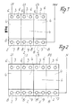
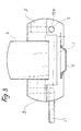
- Surge protection devices are shown in the drawing. They consist of several side-by-side overvoltage protection elements, each overvoltage protection element having a U-shaped lower housing part 1 with contact tongues or similar contact parts, which are arranged within the hollow legs 2, 3, and a rectangular upper part 4 with contact rails or knives emerging on the narrow sides , which is inserted between the legs 2,3.
- the lower parts 1 are fastened, for example, on a top-hat rail 5 and arranged closely next to one another, as can be seen from the top views according to FIGS. 1 and 2.
- the contact tongues and the access slots for this in the legs 2 and 3 and the contact rails in the upper parts 4 are not shown.
- two contact terminals are provided for connecting leads to be connected, for example L 1 , L 2 , L 3 or PE, the respective connecting lead being insertable into an opening in the hollow leg 3, which is open from the side of the legs 3 opens out, which faces away from the narrow side of the upper part 4.
- the respective connecting lead By screws accessible from the head side of the lower part 1, which are arranged in the upwardly open channels 6, clamping screws can be tightened after the introduction of the corresponding conductor into the terminals, so that the conductors are fixed in the terminal.
- the second legs 2 have openings for inserting the N or PEN conductor, which open out from the side surfaces of the leg 2 and run coaxially to the corresponding openings of adjacent lower housing parts 1, so that a continuous insertion channel 7 for the N or PEN Conductor is formed by all legs 2 and corresponding contact terminals.
- a clamping screw can be actuated to close the respective contact terminal through channels 8 opening out at the head side of the lower part 1. In this way, all overvoltage protection elements are bridged together by the PEN conductor or the N conductor, it being only necessary to remove insulation from the corresponding conductor over the entire insertion length, so that correct contacting is made possible.
- the invention is not based on the embodiment limited, but within the scope of the revelation often variable.
Landscapes
- Emergency Protection Circuit Devices (AREA)
Applications Claiming Priority (2)
| Application Number | Priority Date | Filing Date | Title |
|---|---|---|---|
| DE10011249 | 2000-03-08 | ||
| DE2000111249 DE10011249B4 (de) | 2000-03-08 | 2000-03-08 | Vorrichtung zum Schutz gegen Überspannungen |
Publications (2)
| Publication Number | Publication Date |
|---|---|
| EP1134860A1 true EP1134860A1 (fr) | 2001-09-19 |
| EP1134860B1 EP1134860B1 (fr) | 2003-04-09 |
Family
ID=7633948
Family Applications (1)
| Application Number | Title | Priority Date | Filing Date |
|---|---|---|---|
| EP20010100547 Expired - Lifetime EP1134860B1 (fr) | 2000-03-08 | 2001-01-10 | Dispositif de protection contre les surtensions |
Country Status (2)
| Country | Link |
|---|---|
| EP (1) | EP1134860B1 (fr) |
| DE (1) | DE10011249B4 (fr) |
Families Citing this family (1)
| Publication number | Priority date | Publication date | Assignee | Title |
|---|---|---|---|---|
| DE102005026714B3 (de) * | 2005-06-09 | 2006-12-14 | Siemens Ag | Schutzeinrichtung mit einer Schutzschaltereinheit und mit einer Überspannungsschutzeinheit |
Citations (2)
| Publication number | Priority date | Publication date | Assignee | Title |
|---|---|---|---|---|
| DE3837051C1 (en) * | 1988-10-31 | 1990-03-01 | Phoenix Elektrizitaetsgesellschaft H. Knuemann Gmbh & Co Kg, 4933 Blomberg, De | Overvoltage protection plug for a plurality of cables which are to be protected against overvoltages |
| DE4236584A1 (en) * | 1991-12-17 | 1993-06-24 | Phoenix Contact Gmbh & Co | Overload voltage protector e.g. for use with control and instrumentation equipment - has modular structure with overload elements in housing interconnected by bridging strips. |
Family Cites Families (2)
| Publication number | Priority date | Publication date | Assignee | Title |
|---|---|---|---|---|
| US4159500A (en) * | 1977-11-17 | 1979-06-26 | Reliable Electric Company | Modular line protector |
| DE3639533A1 (de) * | 1986-11-20 | 1988-06-01 | Bettermann Obo Ohg | Steckbarer ueberspannungsableiter fuer elektrische anlagen |
-
2000
- 2000-03-08 DE DE2000111249 patent/DE10011249B4/de not_active Expired - Lifetime
-
2001
- 2001-01-10 EP EP20010100547 patent/EP1134860B1/fr not_active Expired - Lifetime
Patent Citations (2)
| Publication number | Priority date | Publication date | Assignee | Title |
|---|---|---|---|---|
| DE3837051C1 (en) * | 1988-10-31 | 1990-03-01 | Phoenix Elektrizitaetsgesellschaft H. Knuemann Gmbh & Co Kg, 4933 Blomberg, De | Overvoltage protection plug for a plurality of cables which are to be protected against overvoltages |
| DE4236584A1 (en) * | 1991-12-17 | 1993-06-24 | Phoenix Contact Gmbh & Co | Overload voltage protector e.g. for use with control and instrumentation equipment - has modular structure with overload elements in housing interconnected by bridging strips. |
Also Published As
| Publication number | Publication date |
|---|---|
| DE10011249A1 (de) | 2001-09-27 |
| EP1134860B1 (fr) | 2003-04-09 |
| DE10011249B4 (de) | 2005-04-28 |
Similar Documents
| Publication | Publication Date | Title |
|---|---|---|
| DE69712414T2 (de) | Verfahren und Anordung zum schnellen Anschliessen zweier elektrischen Käbel | |
| DE102011113333B4 (de) | Elektrische Reihenklemme und Reihenklemmenblock | |
| DE19959823C2 (de) | Verbindungskabel mit elektrischer Steckverbindung | |
| DE102006003064A1 (de) | Elektrischer Reihenklemmenblock | |
| DE2814069B2 (de) | Vorrichtung und Verfahren zur Herstellung eines löt-, schraub- und abisolierfreien Kontaktes an einem feststehenden Anschlußelement, insbesondere für die Fernmeldelinientechnik | |
| WO2012163716A1 (fr) | Ensemble dispositif de contrôle et de connexion et dispositif de contrôle | |
| DE19617114C2 (de) | Erdungsmodul | |
| DE4127899A1 (de) | Elektrische steckvorrichtung mit phasenwahl | |
| DE19603960A1 (de) | Mehrpoliger Abzweig-Steckverbinder | |
| DE10001553A1 (de) | Vorrichtung zur Schirmung für Anschlussleisten | |
| DE102007026102B3 (de) | Steckverbinder für Leiterplatten | |
| DE2251020C3 (de) | Anschlußvorrichtung | |
| DE3934981C2 (fr) | ||
| DE102004040859B4 (de) | Elektrische Reihenklemme und Prüfstecker zur Verwendung bei einer elektrischen Klemme | |
| DE202006016424U1 (de) | Elektrische Kontaktvorrichtung | |
| DE102014116811A1 (de) | Reihenklemme | |
| EP1134860B1 (fr) | Dispositif de protection contre les surtensions | |
| DE102021134322B4 (de) | Drahtverriegelnder Klemmenblock vom Schraubenfedertyp | |
| DE2320202A1 (de) | Anordnung zur wechselseitigen elektrischen verbindung einer mehrzahl von bauteiletraegern (z.b. von gedruckten leiterplatten) | |
| DE69411294T2 (de) | Anschlussblock für elektrisches Geräte und Leistungsumformer mit einem derartigen Anschlu block | |
| DE3721837C2 (fr) | ||
| DE3209279C2 (fr) | ||
| DE2350775C3 (de) | Drahtwickel-Anschluß für mehrpolige Steckvorrichtungen | |
| DE19507791C1 (de) | Doppel-Steckverbinder | |
| DE2816061A1 (de) | Sockel fuer ein mit steckkontakten versehenes geraet, insbesondere fuer ein relais |
Legal Events
| Date | Code | Title | Description |
|---|---|---|---|
| PUAI | Public reference made under article 153(3) epc to a published international application that has entered the european phase |
Free format text: ORIGINAL CODE: 0009012 |
|
| AK | Designated contracting states |
Kind code of ref document: A1 Designated state(s): FR GB IT Kind code of ref document: A1 Designated state(s): AT BE CH CY DE DK ES FI FR GB GR IE IT LI LU MC NL PT SE TR |
|
| AX | Request for extension of the european patent |
Free format text: AL;LT;LV;MK;RO;SI |
|
| 17P | Request for examination filed |
Effective date: 20010823 |
|
| GRAG | Despatch of communication of intention to grant |
Free format text: ORIGINAL CODE: EPIDOS AGRA |
|
| 17Q | First examination report despatched |
Effective date: 20020107 |
|
| GRAG | Despatch of communication of intention to grant |
Free format text: ORIGINAL CODE: EPIDOS AGRA |
|
| GRAH | Despatch of communication of intention to grant a patent |
Free format text: ORIGINAL CODE: EPIDOS IGRA |
|
| GRAH | Despatch of communication of intention to grant a patent |
Free format text: ORIGINAL CODE: EPIDOS IGRA |
|
| AKX | Designation fees paid |
Free format text: FR GB IT |
|
| REG | Reference to a national code |
Ref country code: DE Ref legal event code: 8566 |
|
| GRAA | (expected) grant |
Free format text: ORIGINAL CODE: 0009210 |
|
| AK | Designated contracting states |
Designated state(s): FR GB IT |
|
| PG25 | Lapsed in a contracting state [announced via postgrant information from national office to epo] |
Ref country code: GB Free format text: LAPSE BECAUSE OF FAILURE TO SUBMIT A TRANSLATION OF THE DESCRIPTION OR TO PAY THE FEE WITHIN THE PRESCRIBED TIME-LIMIT Effective date: 20030409 |
|
| REG | Reference to a national code |
Ref country code: GB Ref legal event code: FG4D Free format text: NOT ENGLISH |
|
| GBV | Gb: ep patent (uk) treated as always having been void in accordance with gb section 77(7)/1977 [no translation filed] |
Effective date: 20030409 |
|
| ET | Fr: translation filed | ||
| PLBE | No opposition filed within time limit |
Free format text: ORIGINAL CODE: 0009261 |
|
| STAA | Information on the status of an ep patent application or granted ep patent |
Free format text: STATUS: NO OPPOSITION FILED WITHIN TIME LIMIT |
|
| 26N | No opposition filed |
Effective date: 20040112 |
|
| PGFP | Annual fee paid to national office [announced via postgrant information from national office to epo] |
Ref country code: IT Payment date: 20120126 Year of fee payment: 12 |
|
| PG25 | Lapsed in a contracting state [announced via postgrant information from national office to epo] |
Ref country code: IT Free format text: LAPSE BECAUSE OF NON-PAYMENT OF DUE FEES Effective date: 20130110 |
|
| PGFP | Annual fee paid to national office [announced via postgrant information from national office to epo] |
Ref country code: FR Payment date: 20140123 Year of fee payment: 14 |
|
| REG | Reference to a national code |
Ref country code: FR Ref legal event code: ST Effective date: 20150930 |
|
| PG25 | Lapsed in a contracting state [announced via postgrant information from national office to epo] |
Ref country code: FR Free format text: LAPSE BECAUSE OF NON-PAYMENT OF DUE FEES Effective date: 20150202 |