EP1134868A2 - Appareil et procédé pour faire fonctionner un stockage d'énergie électrique rechargeable - Google Patents
Appareil et procédé pour faire fonctionner un stockage d'énergie électrique rechargeable Download PDFInfo
- Publication number
- EP1134868A2 EP1134868A2 EP00119190A EP00119190A EP1134868A2 EP 1134868 A2 EP1134868 A2 EP 1134868A2 EP 00119190 A EP00119190 A EP 00119190A EP 00119190 A EP00119190 A EP 00119190A EP 1134868 A2 EP1134868 A2 EP 1134868A2
- Authority
- EP
- European Patent Office
- Prior art keywords
- memory
- data
- module
- model
- during operation
- Prior art date
- Legal status (The legal status is an assumption and is not a legal conclusion. Google has not performed a legal analysis and makes no representation as to the accuracy of the status listed.)
- Granted
Links
Images


Classifications
-
- H—ELECTRICITY
- H02—GENERATION; CONVERSION OR DISTRIBUTION OF ELECTRIC POWER
- H02J—ELECTRIC POWER NETWORKS; CIRCUIT ARRANGEMENTS OR SYSTEMS FOR SUPPLYING OR DISTRIBUTING ELECTRIC POWER; SYSTEMS FOR STORING ELECTRIC ENERGY
- H02J7/00—Circuit arrangements for charging or discharging batteries or for supplying loads from batteries
- H02J7/90—Regulation of charging or discharging current or voltage
- H02J7/92—Regulation of charging or discharging current or voltage with prioritisation of loads or sources
Definitions
- the present invention relates to an apparatus and a method for operating a rechargeable storage for electrical energy.
- fuzzy logic methodology From “Determination of state-of-charge and state-of-health of batteries by fuzzy logic methodology "by Salkind et al., Journal of Power Sources 80, 1999, pages 293 to 300, it is known to use fuzzy logic to charge a state of charge electrochemical accumulator based on frequency-dependent Resistance measurements (electrochemical impedance spectroscopy) of the battery to predict. Finding the membership functions and the rules of fuzzy logic takes place by means of a neural network.
- the adaptive model is preferably implemented using neural networkers and / or fuzzy logic implemented.
- Fig. 1 the overall concept of a charging system is shown schematically, with a Rechargeable storage 10 for electrical energy with a consumer 12 electrical energy.
- a charging module 14 is provided for electrical power to charge the memory 10.
- a combined tax and Prediction module 16 is used based on available data relating to the history and presence of memory 10 forecasts of the current state and create future states of memory 10 which will be used to create the select current loading strategy for the memory 10 and. the charging module 14 to control accordingly.
- the control and prediction module 16 When the memory 10 is started up, the control and prediction module 16 is open Data instructed, which is determined, for example, during the manufacture of the memory 10 were and describe the state of the memory 10 before commissioning. in the In operation, the module 16 then continuously collects current measurement data, i.e. the one from the Energy storage 10 withdrawn or supplied to him, the voltage of the Energy storage 10 and variables derived therefrom, in particular the temporal Change in current and voltage, with this captured data in the forecasts are used to update and optimize them. For data collection is included a data acquisition module 22 is provided, which is not shown in FIG. 1.
- An essential aspect is that the predictions of the prediction module 16 be created using an adaptive model, the model being designed such that it continuously on the basis of those recorded by the data acquisition module during operation Measurement data is optimized.
- the adaptive model is preferably based on one So-called neuro-fuzzy logic, as will be explained in more detail below.
- the Information regarding the operating history of the memory 10 is therefore in the continuous improvement of the model for the special memory 10 by the Continuous adaptation via the current measured values, so that the operating history of the Memory 10 is automatically taken into account when creating state forecasts.
- an interface indicated by 18 in FIG. 1 is provided, so that on the one hand from the prediction module 16 predicts the energy storage 10 can be output and, on the other hand, the user can access the charging system can, for example, to implement an emergency stop function or special updated To enter data relating to the energy store 10 so that it can be used by the adaptive Model can be considered.
- electrochemical batteries such as NiCd, NiMH, Li-ion, Li, Pb, AgMH, Zn / MnO 2 cells
- fuel cells such as AFC (alkali fuel cell), PEM (polymer electrolyte fuel cell) ), DMFC (direct methanol fuel cell), PAFC (phosphoric acid fuel cell), MCFC (liquid carbonate fuel cell), SOFC (solid oxide fuel cell), passive components such as special capacitors, and combinations thereof.
- a Control logic 40 controls the output of the charging module 14 to the energy store 10, by passing the flow via a driver / limiter 42 which has a switch-off facility controls electrical power via an energy interface 44, the can be wired or wired, is provided.
- a direct current generator 46 to create the control signals for the driver / limiter are provided.
- the switch 56 is, for example, for pulsed Signals or to switch off.
- the DC generator 46, the AC generator 48, the frequency synthesizer 50 and the switch 56 are controlled directly by the control logic 40.
- the charging module is for great flexibility designed and can DC and AC signals with constant current or constant Deliver voltage that can be pulsed and / or modulated.
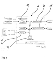
- FIG. 3 schematically shows an example of the structure of the control and prediction module 16.
- the core is formed by a neuro-fuzzy logic, designated 20, which is designed in this way may be that the membership functions and the rules are found by means of a or several neural networks. Examples of the use of neuro-fuzzy logic can be found in the article by Salkind et al. It there are various software toolboxes for neural networks and fuzzy logic, e.g. in the programming language Matlab, whereby many of these toolboxes were obtained from the Internet can be. Among them is a number of toolboxes, one combined use of fuzzy logic and neural networks in the sense of a Allow neuro-fuzzy logic.
- a hybrid neuro-fuzzy logic can also be used, which can be designed for example in two stages, the Input data, for example, fed into two different neuro-fuzzy logics into a third neuro-fuzzy logic as Input values are fed in, whereby their output values ultimately the desired Deliver result.
- An example of a hybrid system is in K. M. Bossley, Neurofuzzy Modeling Approaches in System Identification, Ph.D. Thesis. University of Victoria, Department of Electronics and Computer Science, 1997.
- An essential task of the prediction module 16 consists of known data for the energy store 10, which represent the operating history of the same, Forecasts regarding the current storage status as well as regarding the Development of the storage state to win in the future. It should from the an accurate forecast can be made for existing data records.
- Changes in the properties of the accumulator occur, which are slow develop and move in very small sizes, such as Corrosion reactions or slow changes in mechanical and geometric properties.
- the commonly used simple analytical Accumulator models are unable to make such changes in accumulator properties to model with sufficient accuracy. In particular, they are unable to from the easily accessible measurands, i.e.
- type data i.e. Data specific to the type of energy storage 10 are, be or specific data for the special energy storage 10, such as For example, data that were determined during the manufacture of the energy store 10. This is physical or chemical data, for example the mass, Dimensions or geometric parameters, the porosity and grain sizes including their spatial distributions as well as electrical characteristics like that frequency-dependent impedance of the memory 10.
- a start configuration the neuro-fuzzy logic 20 is preset.
- the prediction module 16 can be recorded by means of a measurement module 22 current measurement data, for example for the current from or to the memory 10 and the voltage present at the memory connections, in each case as a function of time, gain which as data records for later use in a data storage 24 can be saved.
- the neuro-fuzzy logic 20 undergoes regular post-training in order to Continuously improve prediction accuracy for the special energy store 10, i.e. the model of the memory 10 becomes more precise as the operating time increases.
- An essential aspect of the invention is that in this way not only current measured values are used for forecasts regarding the storage state, but rather the entire operating history of the store 10 long-term forecasts in the future, for example regarding the lifespan of the Memory 10.
- the measurement data records obtained are expediently processed prior to processing processed by the neuro-fuzzy logic 20. It can for example a wavelet transform can be used to add noise eliminate and without significant loss of accuracy a data compression to make. However, statistical methods can also be used.
- the neuro-fuzzy logic 20 operates an action predictor module 26 and an information prediction module 28.
- the action prediction module 26 serves the Predictions of neuro-fuzzy logic 20 in short and long-term control of the Implement charging module 14, such a charging strategy being chosen, for example can be that the life expectancy of the energy storage 10 is optimized.
- the Information predictor module 28 serves as an interface 18 with the user for example the current prognosis for the life expectancy of the energy store 10 and help for its maintenance or until the next necessary Charging time remaining at the current load by the Spend consumer 12. It is also possible, for example, to output how long the charging process is still ongoing.
- the user can use this interface also influence the control of the charging module 14, for example by giving an emergency stop signal enters.
- the user can also update, for example Enter expert knowledge regarding the type of energy storage used, what is of particular interest if the service life of the energy store 10 is over spans many years.
- the energy store 10 is preferably the energy supply part an implant in the human body, for example a hearing system.
- the energy store is charged by transcutaneously transmitting electrical energy Energy which from an energy transmission part of the charging module 14 to a corresponding one Energy receiving part of the energy store 10 is sent out.
- FIG. 4 shows the data flow of the neuro-fuzzy logic 20 of the prediction module 16 schematically.
- the Available data is divided into learning data, validation data and test data.
- the learning data are fed into the neuro-fuzzy logic and the Parameters of the same changed until the corresponding to the input data associated target values are reproduced as well as possible.
- Validation data can then be used to check the learning success.
- learning and validation can also take place simultaneously.
- a final review of the model can be made.
- the initial parameters of the neuro-fuzzy logic can also be determined externally and then transferred to the charge control.
Landscapes
- Engineering & Computer Science (AREA)
- Power Engineering (AREA)
- Charge And Discharge Circuits For Batteries Or The Like (AREA)
- Secondary Cells (AREA)
Applications Claiming Priority (2)
| Application Number | Priority Date | Filing Date | Title |
|---|---|---|---|
| DE10012964A DE10012964A1 (de) | 2000-03-16 | 2000-03-16 | Vorrichtung und Verfahren zum Betreiben eines wiederaufladbaren Speichers für elektrische Energie |
| DE10012964 | 2000-03-16 |
Publications (3)
| Publication Number | Publication Date |
|---|---|
| EP1134868A2 true EP1134868A2 (fr) | 2001-09-19 |
| EP1134868A3 EP1134868A3 (fr) | 2003-10-22 |
| EP1134868B1 EP1134868B1 (fr) | 2007-11-21 |
Family
ID=7635051
Family Applications (1)
| Application Number | Title | Priority Date | Filing Date |
|---|---|---|---|
| EP00119190A Expired - Lifetime EP1134868B1 (fr) | 2000-03-16 | 2000-09-05 | Appareil pour faire fonctionner un stockage d'énergie électrique rechargeable |
Country Status (3)
| Country | Link |
|---|---|
| US (1) | US6392386B2 (fr) |
| EP (1) | EP1134868B1 (fr) |
| DE (2) | DE10012964A1 (fr) |
Cited By (2)
| Publication number | Priority date | Publication date | Assignee | Title |
|---|---|---|---|---|
| US7425832B2 (en) | 2003-02-04 | 2008-09-16 | Hydrogenics Corporation | System and method for measuring internal resistance of electrochemical devices |
| DE102019208071A1 (de) * | 2019-06-04 | 2020-12-10 | Robert Bosch Gmbh | Verfahren und Vorrichtung zur Durchführung einer Ladestrategie für Energiespeicher |
Families Citing this family (25)
| Publication number | Priority date | Publication date | Assignee | Title |
|---|---|---|---|---|
| WO1998040951A1 (fr) * | 1997-03-12 | 1998-09-17 | Us Nanocorp. | Procede pour determiner l'etat de sante au moyen d'un systeme intelligent |
| US6879809B1 (en) * | 1998-04-16 | 2005-04-12 | Motorola, Inc. | Wireless electrostatic charging and communicating system |
| US6928371B1 (en) * | 2000-02-08 | 2005-08-09 | Paul T. Roshau | Monitoring system of VRLA battery capacitance |
| TW539932B (en) * | 2000-08-11 | 2003-07-01 | Nisource Energy Technologies | Energy management system and methods for the optimization of distributed generation |
| US20040202900A1 (en) * | 2003-04-09 | 2004-10-14 | Pavio Jeanne S. | Dual power source switching control |
| DE102004025123A1 (de) † | 2004-05-21 | 2005-07-21 | Siemens Audiologische Technik Gmbh | Hörhilfegerät oder Hörgerätesystem mit akustischer Batterieanzeige |
| KR100793616B1 (ko) * | 2005-06-13 | 2008-01-10 | 주식회사 엘지화학 | 배터리 잔존량 추정 장치 및 방법 |
| KR100911316B1 (ko) * | 2007-08-23 | 2009-08-11 | 주식회사 엘지화학 | 배터리의 장기 특성 예측 시스템 및 방법 |
| KR100936892B1 (ko) * | 2007-09-13 | 2010-01-14 | 주식회사 엘지화학 | 배터리의 장기 특성 예측 시스템 및 방법 |
| US20090112395A1 (en) * | 2007-10-31 | 2009-04-30 | Toyota Motor Engineering & Manufacturing North America, Inc.. | System for detecting a battery malfunction and performing battery mitigation for an hev |
| CN101656425B (zh) * | 2009-06-23 | 2011-07-20 | 南京师范大学 | 电动车蓄电池远距离充电装置 |
| DE102009042193A1 (de) * | 2009-09-18 | 2011-03-31 | Bayerische Motoren Werke Aktiengesellschaft | Verfahren zur Schätzung des Innenwiderstands- bzw. Impedanzwerts einer Batterie |
| US8594806B2 (en) | 2010-04-30 | 2013-11-26 | Cyberonics, Inc. | Recharging and communication lead for an implantable device |
| DE102012204828B4 (de) * | 2012-03-26 | 2021-03-18 | Vitesco Technologies GmbH | Steuern eines Niedervolt- und eines Hochvolt-Bordnetzes in einem elektromobilen Kraftfahrzeug |
| US9316699B2 (en) * | 2012-04-05 | 2016-04-19 | Samsung Sdi Co., Ltd. | System for predicting lifetime of battery |
| US9343923B2 (en) | 2012-08-23 | 2016-05-17 | Cyberonics, Inc. | Implantable medical device with backscatter signal based communication |
| US9935498B2 (en) | 2012-09-25 | 2018-04-03 | Cyberonics, Inc. | Communication efficiency with an implantable medical device using a circulator and a backscatter signal |
| JP6277864B2 (ja) * | 2014-05-26 | 2018-02-14 | 株式会社デンソー | 電池内部状態推定装置 |
| WO2016001931A1 (fr) * | 2014-07-02 | 2016-01-07 | Humavox Ltd. | Système de gestion de puissance basé sur l'informatique en nuage pour dispositifs électroniques |
| US10288548B2 (en) * | 2015-04-17 | 2019-05-14 | Hamilton Sundstrand Corporation | Wavelet-based analysis for fouling diagnosis of an aircraft heat exchanger |
| RU2624640C1 (ru) * | 2016-04-25 | 2017-07-05 | ФЕДЕРАЛЬНОЕ ГОСУДАРСТВЕННОЕ КАЗЕННОЕ ВОЕННОЕ ОБРАЗОВАТЕЛЬНОЕ УЧРЕЖДЕНИЕ ВЫСШЕГО ОБРАЗОВАНИЯ "Военная академия Ракетных войск стратегического назначения имени Петра Великого" МИНИСТЕРСТВА ОБОРОНЫ РОССИЙСКОЙ ФЕДЕРАЦИИ | Устройство регулирования балластной нагрузкой аккумуляторных батарей на основе искусственной нейронечеткой сети |
| KR102768452B1 (ko) * | 2019-04-05 | 2025-02-13 | 주식회사 엘지에너지솔루션 | 배터리 관리 장치 및 방법 |
| KR102424916B1 (ko) * | 2021-10-14 | 2022-07-22 | 모나일렉트릭 주식회사 | 배터리 진단 방법 및 그 장치 |
| CN114509637B (zh) * | 2022-04-19 | 2022-08-16 | 深圳市森树强电子科技有限公司 | 一种充电器充放电评估方法 |
| DE102023130120A1 (de) * | 2023-10-31 | 2025-04-30 | reLi Energy GmbH | System und Verfahren zum optimierten Steuern einer Batterie |
Family Cites Families (8)
| Publication number | Priority date | Publication date | Assignee | Title |
|---|---|---|---|---|
| AU630603B2 (en) | 1988-03-11 | 1992-11-05 | Gerhard Wiesspeiner | Process and circuit versions for charging accumulators |
| DE4104359A1 (de) * | 1991-02-13 | 1992-08-20 | Implex Gmbh | Ladesystem fuer implantierbare hoerhilfen und tinnitus-maskierer |
| US5714866A (en) * | 1994-09-08 | 1998-02-03 | National Semiconductor Corporation | Method and apparatus for fast battery charging using neural network fuzzy logic based control |
| FR2740555A1 (fr) * | 1995-10-31 | 1997-04-30 | Philips Electronique Lab | Systeme de controle des cycles de charge-decharge d'une batterie rechargeable, et dispositif hote muni d'une batterie intelligente |
| FR2740554A1 (fr) * | 1995-10-31 | 1997-04-30 | Philips Electronique Lab | Systeme de controle de la phase de decharge des cycles de charge-decharge d'une batterie rechargeable, et dispositif hote muni d'une batterie intelligente |
| US5739672A (en) * | 1996-05-08 | 1998-04-14 | United Continental | Method and apparatus for charging batteries |
| US6064180A (en) * | 1996-10-29 | 2000-05-16 | General Motors Corporation | Method and apparatus for determining battery state-of-charge using neural network architecture |
| US6011379A (en) * | 1997-03-12 | 2000-01-04 | U.S. Nanocorp, Inc. | Method for determining state-of-charge using an intelligent system |
-
2000
- 2000-03-16 DE DE10012964A patent/DE10012964A1/de not_active Withdrawn
- 2000-09-05 EP EP00119190A patent/EP1134868B1/fr not_active Expired - Lifetime
- 2000-09-05 DE DE50014798T patent/DE50014798D1/de not_active Expired - Lifetime
-
2001
- 2001-03-16 US US09/809,087 patent/US6392386B2/en not_active Expired - Lifetime
Cited By (2)
| Publication number | Priority date | Publication date | Assignee | Title |
|---|---|---|---|---|
| US7425832B2 (en) | 2003-02-04 | 2008-09-16 | Hydrogenics Corporation | System and method for measuring internal resistance of electrochemical devices |
| DE102019208071A1 (de) * | 2019-06-04 | 2020-12-10 | Robert Bosch Gmbh | Verfahren und Vorrichtung zur Durchführung einer Ladestrategie für Energiespeicher |
Also Published As
| Publication number | Publication date |
|---|---|
| US20010022509A1 (en) | 2001-09-20 |
| EP1134868A3 (fr) | 2003-10-22 |
| EP1134868B1 (fr) | 2007-11-21 |
| US6392386B2 (en) | 2002-05-21 |
| DE50014798D1 (de) | 2008-01-03 |
| DE10012964A1 (de) | 2001-10-04 |
Similar Documents
| Publication | Publication Date | Title |
|---|---|---|
| EP1134868B1 (fr) | Appareil pour faire fonctionner un stockage d'énergie électrique rechargeable | |
| DE102020212299A1 (de) | Verfahren und Vorrichtung zum Betreiben eines Systems zum Bereitstellen von prädizierten Alterungszuständen von elektrischen Energiespeichern für ein Gerät mithilfe von maschinellen Lernverfahren | |
| DE102020215297A1 (de) | Verfahren und Vorrichtung zum Betreiben eines Systems zum Bereitstellen von prädizierten Alterungszuständen von elektrischen Energiespeichern für ein Gerät mithilfe von maschinellen Lernverfahren | |
| EP2997637B1 (fr) | Procédé et dispositif de charge d'éléments accumulateurs rechargeables | |
| DE102020206592A1 (de) | Verfahren und Vorrichtung zum Betreiben eines elektrisch antreibbaren Kraftfahrzeugs abhängig von einem prädizierten Alterungszustands eines elektrischen Energiespeichers | |
| DE102022212239A1 (de) | Verfahren und Vorrichtung zur prädiktiven Diagnose einer Gerätebatterie eines technischen Geräts mithilfe eines multivariaten Transformer-Modells | |
| DE102017125274B3 (de) | Verfahren zur Erfassung des Gesundheitszustands einer Batterie, zugehörige Einrichtung, zugehöriges System und Speichermedium | |
| DE102019111979A1 (de) | Charakterisierung von wiederaufladbaren Batterien | |
| DE102022200008A1 (de) | Verfahren und System zum effizienten Überwachen von Batteriezellen einer Gerätebatterie in einer geräteexternen Zentraleinheit mithilfe eines digitalen Zwillings | |
| EP3978306A1 (fr) | Procédé et dispositif d'amélioration spécifique à une machine de la durée de vie d'une batterie dans une machine fonctionnant sur batterie | |
| EP3974246A1 (fr) | Procédé et dispositif de prédiction solide du comportement de vieillissement d'un accumulateur d'énergie dans une machine fonctionnant sur batterie | |
| DE102019202014A1 (de) | Vorrichtung und Verfahren zur Berechnung einer Ladedauer und Verfahren zur Optimierung einer Route | |
| DE102021212689A1 (de) | Verfahren und Vorrichtung zum Bereitstellen eines prädizierten Alterungszustands einer Gerätebatterie basierend auf einem prädizierten Nutzungsmuster | |
| DE102022202882A1 (de) | Verfahren und Vorrichtung zum Bereitstellen eines prädizierten Alterungszustands einer Gerätebatterie basierend auf einem prädizierten Nutzungsmuster | |
| DE102022200006A1 (de) | Verfahren und Vorrichtung zum Betreiben einer Vielzahl von batteriebetriebenen Geräten mit austauschbaren Gerätebatterien sowie Batteriewechselstation mit vorausschauender Zuweisung | |
| DE102021208340A1 (de) | Verfahren und Vorrichtung zum Bereitstellen eines berechneten und prädizierten Alterungszustands eines elektrischen Energiespeichers mit einem mithilfe von maschinellen Lernverfahren und Active Learning-Methoden ermittelten Alterungszustandsmodell | |
| DE102021213948A1 (de) | Verfahren und Vorrichtung zum Bereitstellen eines datenbasierten Alterungszustandsmodells zum Bestimmen eines Alterungszustands eines elektrischen Energiespeichers für ein Gerät mithilfe von maschinellen Lernverfahren | |
| DE102020124096A1 (de) | Verfahren und vorrichtung zum ladungsausgleich von batteriezellen | |
| DE102020212236A1 (de) | Verfahren und Vorrichtung zum Betreiben eines Systems zum Bereitstellen von Alterungszuständen von elektrischen Energiespeichern für eine Vielzahl von Geräten mithilfe von maschinellen Lernverfahren | |
| DE102021214154A1 (de) | Computerimplementiertes Verfahren zum Bereitstellen eines Alterungszustandsmodells zur Bestimmung eines aktuellen und prädizierten Alterungszustands eines elektrischen Energiespeichers mithilfe von maschinellen Lernverfahren | |
| DE102021205879A1 (de) | Verfahren und Vorrichtung zum Betreiben eines Systems zum Bereitstellen von prädizierten Alterungszuständen von elektrischen Energiespeichern für ein Gerät mithilfe von maschinellen Lernverfahren | |
| DE102023202789A1 (de) | Verfahren und Vorrichtung zum Bereitstellen von geeigneten Ladeprofilen für Gerätebatterien von batteriebetriebenen Geräten | |
| WO2014166666A1 (fr) | Procédé et dispositif de détermination d'une variable d'état d'un élément de batterie | |
| WO2021073964A1 (fr) | Procédé de réglage d'une surtension d'anode d'une batterie lithium-ion, procédé d'amélioration d'un état de capacité de santé de la batterie lithium-ion | |
| BE1030866B1 (de) | Computerprogramm und Verfahren zur Analyse von Inhomogenitäten sowie Anomaliedetektion und -vorhersage von elektrischen Energiespeichern |
Legal Events
| Date | Code | Title | Description |
|---|---|---|---|
| PUAI | Public reference made under article 153(3) epc to a published international application that has entered the european phase |
Free format text: ORIGINAL CODE: 0009012 |
|
| AK | Designated contracting states |
Kind code of ref document: A2 Designated state(s): AT BE CH CY DE DK ES FI FR GB GR IE IT LI LU MC NL PT SE |
|
| AX | Request for extension of the european patent |
Free format text: AL;LT;LV;MK;RO;SI |
|
| RAP1 | Party data changed (applicant data changed or rights of an application transferred) |
Owner name: COCHLEAR LIMITED |
|
| PUAL | Search report despatched |
Free format text: ORIGINAL CODE: 0009013 |
|
| AK | Designated contracting states |
Kind code of ref document: A3 Designated state(s): AT BE CH CY DE DK ES FI FR GB GR IE IT LI LU MC NL PT SE |
|
| AX | Request for extension of the european patent |
Extension state: AL LT LV MK RO SI |
|
| RIC1 | Information provided on ipc code assigned before grant |
Ipc: 7G 01R 31/36 B Ipc: 7H 02J 7/00 A Ipc: 7A 61N 1/378 B Ipc: 7G 05B 13/02 B |
|
| 17P | Request for examination filed |
Effective date: 20040408 |
|
| AKX | Designation fees paid |
Designated state(s): AT BE CH CY DE DK ES FI FR GB GR IE IT LI LU MC NL PT SE |
|
| 17Q | First examination report despatched |
Effective date: 20050221 |
|
| RTI1 | Title (correction) |
Free format text: APPARATUS FOR OPERATION OF A RECHARGEABLE ELECTRICAL ENERGY STORAGE DEVICE |
|
| GRAP | Despatch of communication of intention to grant a patent |
Free format text: ORIGINAL CODE: EPIDOSNIGR1 |
|
| GRAS | Grant fee paid |
Free format text: ORIGINAL CODE: EPIDOSNIGR3 |
|
| GRAA | (expected) grant |
Free format text: ORIGINAL CODE: 0009210 |
|
| AK | Designated contracting states |
Kind code of ref document: B1 Designated state(s): AT BE CH CY DE DK ES FI FR GB GR IE IT LI LU MC NL PT SE |
|
| REG | Reference to a national code |
Ref country code: GB Ref legal event code: FG4D Free format text: NOT ENGLISH |
|
| REG | Reference to a national code |
Ref country code: IE Ref legal event code: FG4D Free format text: LANGUAGE OF EP DOCUMENT: GERMAN |
|
| REG | Reference to a national code |
Ref country code: CH Ref legal event code: EP |
|
| REF | Corresponds to: |
Ref document number: 50014798 Country of ref document: DE Date of ref document: 20080103 Kind code of ref document: P |
|
| GBT | Gb: translation of ep patent filed (gb section 77(6)(a)/1977) |
Effective date: 20080123 |
|
| PG25 | Lapsed in a contracting state [announced via postgrant information from national office to epo] |
Ref country code: NL Free format text: LAPSE BECAUSE OF FAILURE TO SUBMIT A TRANSLATION OF THE DESCRIPTION OR TO PAY THE FEE WITHIN THE PRESCRIBED TIME-LIMIT Effective date: 20071121 Ref country code: ES Free format text: LAPSE BECAUSE OF FAILURE TO SUBMIT A TRANSLATION OF THE DESCRIPTION OR TO PAY THE FEE WITHIN THE PRESCRIBED TIME-LIMIT Effective date: 20080304 Ref country code: SE Free format text: LAPSE BECAUSE OF FAILURE TO SUBMIT A TRANSLATION OF THE DESCRIPTION OR TO PAY THE FEE WITHIN THE PRESCRIBED TIME-LIMIT Effective date: 20080221 |
|
| NLV1 | Nl: lapsed or annulled due to failure to fulfill the requirements of art. 29p and 29m of the patents act | ||
| PG25 | Lapsed in a contracting state [announced via postgrant information from national office to epo] |
Ref country code: FI Free format text: LAPSE BECAUSE OF FAILURE TO SUBMIT A TRANSLATION OF THE DESCRIPTION OR TO PAY THE FEE WITHIN THE PRESCRIBED TIME-LIMIT Effective date: 20071121 |
|
| ET | Fr: translation filed | ||
| PG25 | Lapsed in a contracting state [announced via postgrant information from national office to epo] |
Ref country code: DK Free format text: LAPSE BECAUSE OF FAILURE TO SUBMIT A TRANSLATION OF THE DESCRIPTION OR TO PAY THE FEE WITHIN THE PRESCRIBED TIME-LIMIT Effective date: 20071121 |
|
| PLBE | No opposition filed within time limit |
Free format text: ORIGINAL CODE: 0009261 |
|
| STAA | Information on the status of an ep patent application or granted ep patent |
Free format text: STATUS: NO OPPOSITION FILED WITHIN TIME LIMIT |
|
| PG25 | Lapsed in a contracting state [announced via postgrant information from national office to epo] |
Ref country code: PT Free format text: LAPSE BECAUSE OF FAILURE TO SUBMIT A TRANSLATION OF THE DESCRIPTION OR TO PAY THE FEE WITHIN THE PRESCRIBED TIME-LIMIT Effective date: 20080421 |
|
| REG | Reference to a national code |
Ref country code: IE Ref legal event code: FD4D |
|
| 26N | No opposition filed |
Effective date: 20080822 |
|
| PG25 | Lapsed in a contracting state [announced via postgrant information from national office to epo] |
Ref country code: IE Free format text: LAPSE BECAUSE OF FAILURE TO SUBMIT A TRANSLATION OF THE DESCRIPTION OR TO PAY THE FEE WITHIN THE PRESCRIBED TIME-LIMIT Effective date: 20071121 |
|
| PG25 | Lapsed in a contracting state [announced via postgrant information from national office to epo] |
Ref country code: GR Free format text: LAPSE BECAUSE OF FAILURE TO SUBMIT A TRANSLATION OF THE DESCRIPTION OR TO PAY THE FEE WITHIN THE PRESCRIBED TIME-LIMIT Effective date: 20080222 |
|
| BERE | Be: lapsed |
Owner name: COCHLEAR LTD Effective date: 20080930 |
|
| PG25 | Lapsed in a contracting state [announced via postgrant information from national office to epo] |
Ref country code: MC Free format text: LAPSE BECAUSE OF NON-PAYMENT OF DUE FEES Effective date: 20080930 |
|
| REG | Reference to a national code |
Ref country code: CH Ref legal event code: PL |
|
| PG25 | Lapsed in a contracting state [announced via postgrant information from national office to epo] |
Ref country code: BE Free format text: LAPSE BECAUSE OF NON-PAYMENT OF DUE FEES Effective date: 20080930 Ref country code: CY Free format text: LAPSE BECAUSE OF FAILURE TO SUBMIT A TRANSLATION OF THE DESCRIPTION OR TO PAY THE FEE WITHIN THE PRESCRIBED TIME-LIMIT Effective date: 20071121 |
|
| PG25 | Lapsed in a contracting state [announced via postgrant information from national office to epo] |
Ref country code: LI Free format text: LAPSE BECAUSE OF NON-PAYMENT OF DUE FEES Effective date: 20080930 Ref country code: CH Free format text: LAPSE BECAUSE OF NON-PAYMENT OF DUE FEES Effective date: 20080930 |
|
| PG25 | Lapsed in a contracting state [announced via postgrant information from national office to epo] |
Ref country code: LU Free format text: LAPSE BECAUSE OF NON-PAYMENT OF DUE FEES Effective date: 20080905 |
|
| PG25 | Lapsed in a contracting state [announced via postgrant information from national office to epo] |
Ref country code: IT Free format text: LAPSE BECAUSE OF NON-PAYMENT OF DUE FEES Effective date: 20080930 |
|
| PGFP | Annual fee paid to national office [announced via postgrant information from national office to epo] |
Ref country code: AT Payment date: 20120829 Year of fee payment: 13 |
|
| REG | Reference to a national code |
Ref country code: AT Ref legal event code: MM01 Ref document number: 379301 Country of ref document: AT Kind code of ref document: T Effective date: 20130905 |
|
| PG25 | Lapsed in a contracting state [announced via postgrant information from national office to epo] |
Ref country code: AT Free format text: LAPSE BECAUSE OF NON-PAYMENT OF DUE FEES Effective date: 20130905 |
|
| REG | Reference to a national code |
Ref country code: FR Ref legal event code: PLFP Year of fee payment: 16 |
|
| PGFP | Annual fee paid to national office [announced via postgrant information from national office to epo] |
Ref country code: GB Payment date: 20150902 Year of fee payment: 16 Ref country code: DE Payment date: 20150902 Year of fee payment: 16 |
|
| PGFP | Annual fee paid to national office [announced via postgrant information from national office to epo] |
Ref country code: FR Payment date: 20150908 Year of fee payment: 16 |
|
| REG | Reference to a national code |
Ref country code: DE Ref legal event code: R119 Ref document number: 50014798 Country of ref document: DE |
|
| GBPC | Gb: european patent ceased through non-payment of renewal fee |
Effective date: 20160905 |
|
| REG | Reference to a national code |
Ref country code: FR Ref legal event code: ST Effective date: 20170531 |
|
| PG25 | Lapsed in a contracting state [announced via postgrant information from national office to epo] |
Ref country code: FR Free format text: LAPSE BECAUSE OF NON-PAYMENT OF DUE FEES Effective date: 20160930 Ref country code: GB Free format text: LAPSE BECAUSE OF NON-PAYMENT OF DUE FEES Effective date: 20160905 Ref country code: DE Free format text: LAPSE BECAUSE OF NON-PAYMENT OF DUE FEES Effective date: 20170401 |