EP1134874A1 - Läufer einer rotierenden elektrischen Maschine mit integriertem Kommutator - Google Patents
Läufer einer rotierenden elektrischen Maschine mit integriertem Kommutator Download PDFInfo
- Publication number
- EP1134874A1 EP1134874A1 EP01105044A EP01105044A EP1134874A1 EP 1134874 A1 EP1134874 A1 EP 1134874A1 EP 01105044 A EP01105044 A EP 01105044A EP 01105044 A EP01105044 A EP 01105044A EP 1134874 A1 EP1134874 A1 EP 1134874A1
- Authority
- EP
- European Patent Office
- Prior art keywords
- armature
- commutator
- armature core
- conductor segments
- anchoring
- Prior art date
- Legal status (The legal status is an assumption and is not a legal conclusion. Google has not performed a legal analysis and makes no representation as to the accuracy of the status listed.)
- Granted
Links
- 239000004020 conductor Substances 0.000 claims abstract description 42
- 238000004873 anchoring Methods 0.000 claims abstract description 21
- 230000008602 contraction Effects 0.000 abstract description 2
- 238000009413 insulation Methods 0.000 description 8
- 125000006850 spacer group Chemical group 0.000 description 6
- 239000007858 starting material Substances 0.000 description 5
- 238000003825 pressing Methods 0.000 description 4
- 238000004519 manufacturing process Methods 0.000 description 3
- XEEYBQQBJWHFJM-UHFFFAOYSA-N Iron Chemical compound [Fe] XEEYBQQBJWHFJM-UHFFFAOYSA-N 0.000 description 2
- 241000361919 Metaphire sieboldi Species 0.000 description 1
- 229910052742 iron Inorganic materials 0.000 description 1
- 230000001788 irregular Effects 0.000 description 1
- 230000033001 locomotion Effects 0.000 description 1
- 238000012986 modification Methods 0.000 description 1
- 230000004048 modification Effects 0.000 description 1
- 230000002093 peripheral effect Effects 0.000 description 1
- 239000012260 resinous material Substances 0.000 description 1
Images

Classifications
-
- H—ELECTRICITY
- H02—GENERATION; CONVERSION OR DISTRIBUTION OF ELECTRIC POWER
- H02K—DYNAMO-ELECTRIC MACHINES
- H02K3/00—Details of windings
- H02K3/04—Windings characterised by the conductor shape, form or construction, e.g. with bar conductors
- H02K3/12—Windings characterised by the conductor shape, form or construction, e.g. with bar conductors arranged in slots
-
- H—ELECTRICITY
- H02—GENERATION; CONVERSION OR DISTRIBUTION OF ELECTRIC POWER
- H02K—DYNAMO-ELECTRIC MACHINES
- H02K13/00—Structural associations of current collectors with motors or generators, e.g. brush mounting plates or connections to windings; Disposition of current collectors in motors or generators; Arrangements for improving commutation
- H02K13/04—Connections between commutator segments and windings
- H02K13/08—Segments formed by extensions of the winding
-
- H—ELECTRICITY
- H02—GENERATION; CONVERSION OR DISTRIBUTION OF ELECTRIC POWER
- H02K—DYNAMO-ELECTRIC MACHINES
- H02K3/00—Details of windings
- H02K3/46—Fastening of windings on the stator or rotor structure
- H02K3/48—Fastening of windings on the stator or rotor structure in slots
- H02K3/487—Slot-closing devices
Definitions
- the present invention relates to a rotary electric machine and, particularly, an armature having an integrated commutator at an end thereof.
- U.S.P. 5,739,617 or its corresponding Japanese Patent Application JP-A-9-51645 discloses an armature of a rotary electric machine.
- the armature has an integrated commutator at an end of an armature coil.
- Upper-layer conductor segments and a generally disk-like insulation spacer, which s made of a hard resinous material, are fitted to each other on the end of the armature adjacent a commutator so that axial position of the upper-layer conductor segments can be fixed. Therefore, the commutator surface in contact with the brush can be maintained flat.
- the brush may wear away. As a result, the lifetime of the brush shortens, and electric resistance loss between the commutator and the brush increases.
- the present invention is to provide an armature that has more flat commutator surface.
- upper layer conductor segments are heated in a short time and the temperature thereof rises sharply, difference in thermal expansion are generated between the upper-layer conductor segment and the armature core.
- the upper-layer conductor segments which form the commutator, expand and slide on the armature core due to the thermal expansion. If the upper-layer conductor segments expand uniformly, there is no difference in height on the commutator surface. The difference in height on the commutator surface is generated if the upper-layer conductor segments expand diversely, thereby causing the upper-layer conductor segments to shift diversely.
- positions of the upper-layer conductor segments when thermally expanding may be different from positions thereof when thermally contracting.
- each upper-layer conductor segment moves like an earthworm on the armature core every time it thermally expands and contracts, or shifts as a result of repeated random motions in a certain distance.
- an armature core has an anchoring portion, disposed near the commutator, for anchoring a part of each the conductor segment more strongly than the rest thereof.
- each conductor segment Because a part of each conductor segment is tightly fixed to the anchoring portion, there is no shift of each conductor segment at the anchoring portion relative to the armature core even if each conductor segment thermally expands or contracts. Even if the conductor segments repeats thermal expansion and thermal contraction while the rotary electric machine is operating, the anchored parts of the conductor segments relative to the armature core do not shift. Accordingly, even if the rotary electric machine operates for a long time, there is no height difference on the commutator segment of the armature.
- the lifetime of the brushes is increased and the service cost thereof is reduced.
- the connection resistance between the commutator and the brushes is reduced, thereby improving the performance of the rotary electric machine.
- Each anchored part of the conductor segment is preferably fixed to the armature core at a distance from the commutator as short as possible. If the distance is not short enough, there is some possibility of the height difference on the commutator surface due to irregular friction and others generated between the armature core and the conductor segments . However, it may be disposed at a distance less than a half of the length of the armature core from the end thereof adjacent to the commutator.
- the anchoring portion may be disposed at a space corresponding to one of the laminated sheets of the armature core. If the anchoring portion is disposed at the extreme end of the armature core adjacent to the commutator, there is some possibility of inconvenience. For example, if the anchoring portion is formed by pressing the outer periphery of the armature core, insulation paper sheets that insulate the conductor segments may be broken because a large centrifugal force of the commutator is applied to the anchoring portion. In order to avoid the above problem, the anchoring portion is formed at not the extreme end of the armature core but at least a pace of the laminated sheet from the end.
- the anchoring portion can be formed very easily by a roller.
- the roller is pressed against the outer periphery of the armature core while the armature is being turned.
- the pressed portion has an outside diameter 0.08 % - 0.6 % less than the outside diameter of other portion of the armature core. Therefore, the pressed portion can be formed without severe accuracy of the size, so that the production cost of the armature can be maintained at a low level.
- the pressed portion is formed at the step of applying a stepped punch on the outer periphery of the armature core that is the last step in manufacturing process of the armature, the pressed portion can be formed easily at a low cost. Almost the all parts except the spacer are well known and almost all the steps except the pressing step for forming the pressed portion 22 are well known. As a result, the production cost does not increase very much.
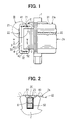
- the armature coil 3 is comprised of a plurality of respectively connected upper conductor segments 4 and lower conductor segments 5 having in-slot portions 40 and 50 inserted into the slots 20 of the armature core 2.
- the armature coil 3 forms a commutator 31 adjacent an axial end of the armature core 2.
- a commutator end 41 has a disk-like commutator surface 31a on a plane that has the axis of the rotary shaft 1 as the normal line thereof, and a plurality of brushes are disposed to be in contact with the commutator surface 31a.
- the upper and lower conductor segments 4 and 5, respectively, have commutator ends 41 and 51 welded to each other at one end of the in-slot portion 40 and 50 and coil ends 42 and 52 at the other end of the in-slot portion 40 and 50.
- the in-slot portion 40 of each upper conductor segment 4 is fitted to resinous insulation spacers 71 and 72 at opposite ends thereof to restrict the axial shift thereof.
- the opposite ends of the in-slot portions 40 of the upper conductor segments 4 fitted to the spacer 71 and 72 are disclosed in U.S.P. 5,739,617 or JP-A-9-51645. Because the opposite ends of the in-slot portions 40 of each upper conductor segment 4 are fitted to the spacer 71 and 72, the height difference is reduced at the opposite ends of the armature coil 3.
- the armature is assembled and the outer surface 2a is formed cylindrical, the armature is rotated with the shaft 1 being supported. Then, a well-known roller (not shown) is pressed against a belt-like portion of the outer surface 2a of the armature core 2 near the commutator 31, thereby forming the pressed portion 22.
Landscapes
- Engineering & Computer Science (AREA)
- Power Engineering (AREA)
- Motor Or Generator Current Collectors (AREA)
- Insulation, Fastening Of Motor, Generator Windings (AREA)
- Manufacture Of Motors, Generators (AREA)
- Dc Machiner (AREA)
- Iron Core Of Rotating Electric Machines (AREA)
Applications Claiming Priority (2)
| Application Number | Priority Date | Filing Date | Title |
|---|---|---|---|
| JP2000070688A JP3644344B2 (ja) | 2000-03-14 | 2000-03-14 | 電機子 |
| JP2000070688 | 2000-03-14 |
Publications (2)
| Publication Number | Publication Date |
|---|---|
| EP1134874A1 true EP1134874A1 (de) | 2001-09-19 |
| EP1134874B1 EP1134874B1 (de) | 2004-10-06 |
Family
ID=18589389
Family Applications (1)
| Application Number | Title | Priority Date | Filing Date |
|---|---|---|---|
| EP01105044A Expired - Lifetime EP1134874B1 (de) | 2000-03-14 | 2001-03-01 | Läufer einer rotierenden elektrischen Maschine mit integriertem Kommutator |
Country Status (4)
| Country | Link |
|---|---|
| US (1) | US6806613B2 (de) |
| EP (1) | EP1134874B1 (de) |
| JP (1) | JP3644344B2 (de) |
| DE (1) | DE60106118T2 (de) |
Families Citing this family (5)
| Publication number | Priority date | Publication date | Assignee | Title |
|---|---|---|---|---|
| WO2011003178A1 (en) | 2009-07-10 | 2011-01-13 | National Research Council Of Canada | Novel pulsed power supply for plasma electrolytic deposition and other processes |
| JP2011036010A (ja) * | 2009-07-31 | 2011-02-17 | Hitachi Ltd | 回転電機 |
| JP5537964B2 (ja) * | 2010-01-19 | 2014-07-02 | 株式会社日立製作所 | 回転電機 |
| CN102270889B (zh) * | 2011-06-21 | 2013-11-06 | 裴亚军 | 一种用于起动机中的电枢 |
| WO2016093267A1 (ja) * | 2014-12-09 | 2016-06-16 | 三菱電機株式会社 | 固定子の製造方法、回転電機の製造方法、および鉄心ブロック |
Citations (5)
| Publication number | Priority date | Publication date | Assignee | Title |
|---|---|---|---|---|
| DE2627647A1 (de) * | 1975-07-11 | 1977-01-27 | Nippon Denso Co | Rotor fuer eine elektrische maschine |
| DE2848618A1 (de) * | 1978-11-09 | 1980-05-22 | Bosch Gmbh Robert | Elektrische maschine und verfahren zu ihrer herstellung |
| DE3230296A1 (de) * | 1982-08-14 | 1984-02-16 | Robert Bosch Gmbh, 7000 Stuttgart | Verfahren zum sichern der wicklung im rotor elektrischer maschinen |
| JPS62247736A (ja) * | 1986-04-18 | 1987-10-28 | Hitachi Ltd | 小型回転電機の電機子及びその製造方法 |
| US5739617A (en) * | 1994-12-14 | 1998-04-14 | Nippondenso Co., Ltd. | Rotary electric machine |
Family Cites Families (8)
| Publication number | Priority date | Publication date | Assignee | Title |
|---|---|---|---|---|
| US4433262A (en) * | 1978-11-30 | 1984-02-21 | General Electric Company | Method of locking conductors in a dynamoelectric machine rotor and rotor having locked conductors |
| US4616151A (en) * | 1984-12-07 | 1986-10-07 | General Motors Corporation | Armature with quiet core construction |
| JPH0732573B2 (ja) * | 1987-06-03 | 1995-04-10 | 株式会社日立製作所 | 回転電機子の製造方法 |
| US5650683A (en) * | 1993-10-15 | 1997-07-22 | Nippondenso Co., Ltd. | Electric rotating machine |
| AU674784B2 (en) * | 1993-10-15 | 1997-01-09 | Nippondenso Co. Ltd. | Electric rotating machine |
| FR2721769B1 (fr) * | 1994-06-22 | 1996-07-26 | Valeo Equip Electr Moteur | Procédé de sertissage de conducteur dans des encoches ouvertes d'un induit de machine électrique tournante et machine électrique, notamment un démarreur de véhicule automobile, comportant un induit selon le procédé. |
| FR2759506B1 (fr) * | 1997-02-07 | 2003-08-15 | Jeumont Ind | Arbre de rotor d'une machine electrique |
| JP3234791B2 (ja) * | 1997-03-06 | 2001-12-04 | マブチモーター株式会社 | 小型モータ |
-
2000
- 2000-03-14 JP JP2000070688A patent/JP3644344B2/ja not_active Expired - Fee Related
-
2001
- 2001-03-01 DE DE60106118T patent/DE60106118T2/de not_active Expired - Lifetime
- 2001-03-01 EP EP01105044A patent/EP1134874B1/de not_active Expired - Lifetime
- 2001-03-13 US US09/803,979 patent/US6806613B2/en not_active Expired - Fee Related
Patent Citations (5)
| Publication number | Priority date | Publication date | Assignee | Title |
|---|---|---|---|---|
| DE2627647A1 (de) * | 1975-07-11 | 1977-01-27 | Nippon Denso Co | Rotor fuer eine elektrische maschine |
| DE2848618A1 (de) * | 1978-11-09 | 1980-05-22 | Bosch Gmbh Robert | Elektrische maschine und verfahren zu ihrer herstellung |
| DE3230296A1 (de) * | 1982-08-14 | 1984-02-16 | Robert Bosch Gmbh, 7000 Stuttgart | Verfahren zum sichern der wicklung im rotor elektrischer maschinen |
| JPS62247736A (ja) * | 1986-04-18 | 1987-10-28 | Hitachi Ltd | 小型回転電機の電機子及びその製造方法 |
| US5739617A (en) * | 1994-12-14 | 1998-04-14 | Nippondenso Co., Ltd. | Rotary electric machine |
Non-Patent Citations (1)
| Title |
|---|
| PATENT ABSTRACTS OF JAPAN vol. 12, no. 118 (E - 600) 13 April 1988 (1988-04-13) * |
Also Published As
| Publication number | Publication date |
|---|---|
| DE60106118T2 (de) | 2005-03-03 |
| US20010022481A1 (en) | 2001-09-20 |
| JP3644344B2 (ja) | 2005-04-27 |
| DE60106118D1 (de) | 2004-11-11 |
| EP1134874B1 (de) | 2004-10-06 |
| JP2001258194A (ja) | 2001-09-21 |
| US6806613B2 (en) | 2004-10-19 |
Similar Documents
| Publication | Publication Date | Title |
|---|---|---|
| EP0649213B1 (de) | Rotierende elektrische Maschine | |
| US4307314A (en) | Barrel-shaped claw-pole rotor for induction type AC generator | |
| JP2003164088A (ja) | 電動機の固定子構造 | |
| CN107546924A (zh) | 电机以及制造该电机的方法 | |
| JP2004201446A (ja) | ステータコア用のウェッジ | |
| US6806613B2 (en) | Commutator integrated armature of electric rotary machine | |
| KR100586784B1 (ko) | 전동파워스티어링 장치용 브러시 모터 | |
| KR100633573B1 (ko) | 회전전기장치의 전기자 및 그의 제조방법 | |
| JP3468809B2 (ja) | 電気機械に用いられるドラム形コレクタ | |
| CN113904512A (zh) | 定子和用于制造电动机器的定子的方法 | |
| CA2199006A1 (en) | Rotary switch | |
| US12500469B2 (en) | Stator for an electric drive unit and method for producing a stator for an electric drive unit | |
| US5739617A (en) | Rotary electric machine | |
| US20090066182A1 (en) | Stator winding assembly and method | |
| US6724124B2 (en) | Rotary electric machine having collar for restricting coil end expansion | |
| KR100386008B1 (ko) | 보강링을 구비한 정류자 | |
| US7877857B2 (en) | Manufacturing method of electric motor | |
| JP2006087172A (ja) | 回転電機の固定子 | |
| JPS5826546A (ja) | スリツプリング装置 | |
| JP3771875B2 (ja) | 回転電機の固定子 | |
| JP4600155B2 (ja) | 電動機 | |
| ZA200204561B (en) | Armature for an electric machine and method for producing the same. | |
| EP1439612B1 (de) | Elektrisches Kontaktelement | |
| US5604391A (en) | Armature | |
| KR20070084528A (ko) | 정류자의 제조 방법 및 정류자 |
Legal Events
| Date | Code | Title | Description |
|---|---|---|---|
| PUAI | Public reference made under article 153(3) epc to a published international application that has entered the european phase |
Free format text: ORIGINAL CODE: 0009012 |
|
| AK | Designated contracting states |
Kind code of ref document: A1 Designated state(s): DE FR IT Kind code of ref document: A1 Designated state(s): AT BE CH CY DE DK ES FI FR GB GR IE IT LI LU MC NL PT SE TR |
|
| AX | Request for extension of the european patent |
Free format text: AL;LT;LV;MK;RO;SI |
|
| 17P | Request for examination filed |
Effective date: 20011015 |
|
| AKX | Designation fees paid |
Free format text: DE FR IT |
|
| 17Q | First examination report despatched |
Effective date: 20021031 |
|
| GRAP | Despatch of communication of intention to grant a patent |
Free format text: ORIGINAL CODE: EPIDOSNIGR1 |
|
| GRAS | Grant fee paid |
Free format text: ORIGINAL CODE: EPIDOSNIGR3 |
|
| GRAA | (expected) grant |
Free format text: ORIGINAL CODE: 0009210 |
|
| AK | Designated contracting states |
Kind code of ref document: B1 Designated state(s): DE FR IT |
|
| REF | Corresponds to: |
Ref document number: 60106118 Country of ref document: DE Date of ref document: 20041111 Kind code of ref document: P |
|
| ET | Fr: translation filed | ||
| PLBE | No opposition filed within time limit |
Free format text: ORIGINAL CODE: 0009261 |
|
| STAA | Information on the status of an ep patent application or granted ep patent |
Free format text: STATUS: NO OPPOSITION FILED WITHIN TIME LIMIT |
|
| 26N | No opposition filed |
Effective date: 20050707 |
|
| PGFP | Annual fee paid to national office [announced via postgrant information from national office to epo] |
Ref country code: FR Payment date: 20100324 Year of fee payment: 10 |
|
| PGFP | Annual fee paid to national office [announced via postgrant information from national office to epo] |
Ref country code: DE Payment date: 20100312 Year of fee payment: 10 |
|
| PGFP | Annual fee paid to national office [announced via postgrant information from national office to epo] |
Ref country code: IT Payment date: 20100313 Year of fee payment: 10 |
|
| REG | Reference to a national code |
Ref country code: FR Ref legal event code: ST Effective date: 20111130 |
|
| PG25 | Lapsed in a contracting state [announced via postgrant information from national office to epo] |
Ref country code: DE Free format text: LAPSE BECAUSE OF NON-PAYMENT OF DUE FEES Effective date: 20111001 Ref country code: FR Free format text: LAPSE BECAUSE OF NON-PAYMENT OF DUE FEES Effective date: 20110331 |
|
| REG | Reference to a national code |
Ref country code: DE Ref legal event code: R119 Ref document number: 60106118 Country of ref document: DE Effective date: 20111001 |
|
| PG25 | Lapsed in a contracting state [announced via postgrant information from national office to epo] |
Ref country code: IT Free format text: LAPSE BECAUSE OF NON-PAYMENT OF DUE FEES Effective date: 20110301 |