EP1134883A2 - Vibrationsmotoren - Google Patents
Vibrationsmotoren Download PDFInfo
- Publication number
- EP1134883A2 EP1134883A2 EP01400606A EP01400606A EP1134883A2 EP 1134883 A2 EP1134883 A2 EP 1134883A2 EP 01400606 A EP01400606 A EP 01400606A EP 01400606 A EP01400606 A EP 01400606A EP 1134883 A2 EP1134883 A2 EP 1134883A2
- Authority
- EP
- European Patent Office
- Prior art keywords
- frequency
- motor according
- resonance mode
- main
- normal
- Prior art date
- Legal status (The legal status is an assumption and is not a legal conclusion. Google has not performed a legal analysis and makes no representation as to the accuracy of the status listed.)
- Granted
Links
Images


Classifications
-
- H—ELECTRICITY
- H02—GENERATION; CONVERSION OR DISTRIBUTION OF ELECTRIC POWER
- H02N—ELECTRIC MACHINES NOT OTHERWISE PROVIDED FOR
- H02N2/00—Electric machines in general using piezoelectric effect, electrostriction or magnetostriction
- H02N2/10—Electric machines in general using piezoelectric effect, electrostriction or magnetostriction producing rotary motion, e.g. rotary motors
-
- H—ELECTRICITY
- H02—GENERATION; CONVERSION OR DISTRIBUTION OF ELECTRIC POWER
- H02N—ELECTRIC MACHINES NOT OTHERWISE PROVIDED FOR
- H02N2/00—Electric machines in general using piezoelectric effect, electrostriction or magnetostriction
- H02N2/02—Electric machines in general using piezoelectric effect, electrostriction or magnetostriction producing linear motion, e.g. actuators; Linear positioners ; Linear motors
Definitions
- the present invention relates to vibration motors.
- Vibration motors are also known as ultrasonic motors to refer to their preferred frequency of use or of piezoactive motors to refer to their material favorite excitement.
- the invention is particularly applicable advantageous in the case of rotary vibration motors, but may also be applied for linear actuators, the term motor to vibrations designating in this text both the rotary motors and the linear actuators.
- a rotary vibration motor comprises at least a stator and a rotor, as well as excitation means for deforming said stator and / or said rotor according to vibratory modes combining vibrations tangential and normal vibrations able to drive the rotor according to a continuous rotational movement.
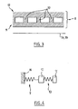
- Such an engine comprises, in a carcass 2, two discs of rotor 1 integral with a shaft 3 and stator plates 4 between which said discs 1 are arranged.
- Each stator plate 4 is made up of a plurality of contact sectors 6 (called stator petals) which are distributed annularly and which are separated two by two by active elements of tangential deformation 7 (piezoelectric elements or others).
- the contact sectors 6 of the two interior plates 4 are on the right of each other.
- Active elements 8 piezoelectric elements or other
- Means 9 forming a spring are interposed between the carcass 2 and the contact sectors 6 of the outer plates 4.
- Active elements 8 for the generation of a normal force and the active elements 7 of deformation tangential are controlled synchronously to drive the rotors 1 in rotation.
- shape memory alloys which are materials exhibiting nonlinear superelasticity and which, with respect to conventional materials, have the advantage of allowing large deformations for smaller quantities of material.
- super-elasticity By super-elasticity is meant here and throughout this text the property for a material to accept reversible elongations of 1% or higher. It is also recalled that the non-linear nature of a super-elasticity results in the presence of a phase change stage on the curve giving the deformation as a function of the tensile force.
- An object of the invention is to further increase the yield of vibration motors.
- EP 0 543 114 already discloses an actuator in which the support contacts between the fixed part and the mobile part are limited at the maximum, so that the energy losses by friction are minimized.
- the surface of contact of the fixed part which constitutes the stator is not rigid, but is deformed by the propagation of a progressive wave which drives the part mobile which constitutes the rotor. Only the top of the continuous deformation is then in contact with the driven part.
- the invention provides a solution which allows to increase the efficiency of vibration motors of the type comprising minus a fixed part and a part driven in movement relative to said fixed part, as well as excitation means capable of exerting forces tending to move rigid contact sectors exhibited by said fixed part and / or said moving part and making these sectors vibrate rigid according to vibratory modes combining tangential vibrations and normal vibrations causing the part to move in movement.
- Said motor having, for tangential vibrations or normal vibrations, a main resonance mode and at least one mode secondary resonance, the proposed solution is that the mode secondary resonance is at a frequency substantially equal to one harmonic frequency of the main resonance mode.
- the moving part can be a disc rotor rigid, said motor comprising a stator which comprises at least one pair of stator trays, each tray having rigid petals suitable for receiving means for moving said rigid petals tangentially and normally.
- the motor can be a linear actuator.
- At least one element having elastic deformation properties is included in the moving part and / or the fixed part, said element being separated from the contact face of said moving part and / or said part.
- fixed by a part forming a pad and the part (s) in which the elastic deformation element (s) are included is (are) dimensioned so that the frequency of the secondary tangential resonance mode - which is the mode of resonance where the shoe part and the rest of the part oscillate in phase opposition - is substantially equal to a frequency which is a harmonic frequency of the main tangential resonance mode - where the shoe part and the rest of the part oscillate in phase .
- the engine has a secondary normal resonant frequency which is substantially a harmonic frequency of the resonant frequency main normal and the excitation means include means for generate normal vibrations at either of these two frequencies of resonance.
- FIG. 3 shows an example of a possible structure. for a petal 6 of a structure of the type of those represented on the Figures 1 and 2.
- This petal 6 is constituted by a metal block which has a main part 12, a contact pad 11 and a field of elements intermediaries 10 interposed between the part 12 and the contact pad 11.
- the intermediate elements 10 are for example pawns, of cylindrical or other shape, suitable in particular for accepting deformations in bending.
- lamellae in particular lamellae of generally flat shape, which extend at rest perpendicular to the general plane of part 12 and which are in particular able to deform elastically in bending under the effect of a force moving the contact pad 11 relative to the part 12 parallel to the general plan in relation to which they extend.
- the elements 10 which constitute the elastic part interposed between the shoe part 11 and the rest of the stator (part 12) is advantageously in a semi-crystalline polymer and in particular polyether-ether-acetone (PEEK).
- PEEK polyether-ether-acetone
- Semi-crystalline polymers and especially PEEK have the advantage of a low modulus of elasticity, a great elongation, a excellent resistance to fatigue and good temperature resistance.
- the elastic intermediate layer can with these materials be consisting of a solid layer which makes it easy to achieve.
- the main part 12, the contact pad 11 and the elements 10 can be molded in one piece from a material allowing the elements 10 to have elastic properties, such as steel.
- the elements 10 are not directly in contact with the rotor 1a or 1b, the petal 6 having a part 11 constituting a contact pad separating said elements 10 of the rotor 1a or 1b on which said petal 6 comes to bear.
- Such a structure is in fact preferable to a structure in which the pins or lamellae 10 would be in direct contact with the rotor, which would pose problems of tribology and in which the contact surface would be reduced.
- shoe-forming part 11 changes the dynamic behavior of the engine due to its mass.
- Sizing includes the choice of geometry and masses of the different parts of the petals, the distribution of these and in particular the distribution of elements 10, etc.
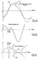
- the curve Xt 12 represents the tangential displacement of the part 12 of a petal 6 and the curve Xt 11 the tangential displacement of the corresponding shoe 11.
- FIG. 5c the evolution of the friction force has been represented. between the stator and the rotor.
- the pins or strips 10 are advantageously in materials having a super-elasticity and including linear super-elasticity.
- the vibration motor which is shown in Figure 7 has a structure similar to that shown in Figures 1 and 2 and we have resumed for the elements of the structure shown in FIGS. 1 and 2 which are find in this figure 3 the same reference numberings increased by 100.
- the structure shown in FIG. 7 comprises, in a carcass 102, two rotor plates 101 each interposed between two stator plates 104.
- the stator plates 104 consist of metallic petals 106 separated by active tangential deformation elements 107.
- a petal 106 is advantageously a metallic petal in which at least one elastically deformable element is included.
- the petal 106 included in the vicinity of its contact surface a field elements 122 such as pins or lamellae, these elements 122 being preferably separated from the contact surface of the petal by a part of it which forms skate.
- Active elements 108 of normal deformation are interposed between the petals 106 of the two internal stator plates 104 (i.e. two stator plates which are included between the two others, which constitute the external stator plates).
- Spring means 109 are interposed between the carcass 102 of the motor and the petals 106 of the two external stator plates 104.
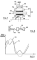
- each petal 106 of the external stator plates carries a complementary mass 120 which is mounted on said petal by through an active element of normal deformation 121 (in a material piezoelectric for example), the means 109 forming a spring coming in support on said mass 120.
- the mass 120 and the active element 121 are dimensioned (geometry, mass, material, etc.) so that the frequency F2 is equal to N * F1, where N is a number, while the motor includes means for exciting said element active 121 at this frequency F2.
- N is chosen to be odd.
- the downforce then obtained is that shown on the Figure 5 (curve C1 in solid lines) and which is substantially clipped by compared to that obtained with the only excitation of the active elements 107 and 108 at frequency F1 (curve C2 in dashed lines).
- a variant of the solution described above consists of replace the paving stone or active element 121 with an equivalent passive stiffness and to supply the main actuator with a frequency excitation N F1 adding to the fundamental excitement at frequency F1.
- a mass 120 and the rest of a petal 106 can be provided between a mass 120 and the rest of a petal 106 a plurality of elements 109 with elastic deformation having different stiffnesses and therefore corresponding to secondary resonance modes different, these elements being chosen so that their frequency corresponds to a harmonic of the main frequency.
Landscapes
- General Electrical Machinery Utilizing Piezoelectricity, Electrostriction Or Magnetostriction (AREA)
- Apparatuses For Generation Of Mechanical Vibrations (AREA)
Applications Claiming Priority (2)
| Application Number | Priority Date | Filing Date | Title |
|---|---|---|---|
| FR0003084A FR2806225B1 (fr) | 2000-03-10 | 2000-03-10 | Moteurs a vibrations |
| FR0003084 | 2000-03-10 |
Publications (3)
| Publication Number | Publication Date |
|---|---|
| EP1134883A2 true EP1134883A2 (de) | 2001-09-19 |
| EP1134883A3 EP1134883A3 (de) | 2001-09-26 |
| EP1134883B1 EP1134883B1 (de) | 2009-10-28 |
Family
ID=8847947
Family Applications (1)
| Application Number | Title | Priority Date | Filing Date |
|---|---|---|---|
| EP01400606A Expired - Lifetime EP1134883B1 (de) | 2000-03-10 | 2001-03-08 | Vibrationsmotoren |
Country Status (7)
| Country | Link |
|---|---|
| US (1) | US6628044B2 (de) |
| EP (1) | EP1134883B1 (de) |
| JP (1) | JP2001298968A (de) |
| CA (1) | CA2340520C (de) |
| DE (1) | DE60140282D1 (de) |
| ES (1) | ES2333198T3 (de) |
| FR (1) | FR2806225B1 (de) |
Families Citing this family (10)
| Publication number | Priority date | Publication date | Assignee | Title |
|---|---|---|---|---|
| JP2001136761A (ja) * | 1999-11-02 | 2001-05-18 | Minolta Co Ltd | アクチュエータ |
| US7161580B2 (en) * | 2002-04-25 | 2007-01-09 | Immersion Corporation | Haptic feedback using rotary harmonic moving mass |
| US7369115B2 (en) | 2002-04-25 | 2008-05-06 | Immersion Corporation | Haptic devices having multiple operational modes including at least one resonant mode |
| FR2844933B1 (fr) * | 2002-09-20 | 2004-11-26 | Sagem | Perfectionnements aux moteurs hautes puissances. |
| DE10301818A1 (de) * | 2003-01-20 | 2004-07-29 | Carl Zeiss Smt Ag | Piezo-Linearantrieb mit einer Gruppe von Piezostapelaktuatoren |
| US7221076B2 (en) * | 2005-07-15 | 2007-05-22 | Avago Technologies General Ip (Singapore) Pte. Ltd. | Multiple movements harmonic frequency actuator system |
| GB2446428B (en) * | 2006-12-02 | 2010-08-04 | Nanomotion Ltd | Controllable coupling force |
| RU2684395C1 (ru) * | 2018-03-26 | 2019-04-09 | Федеральное государственное автономное образовательное учреждение высшего образования "Национальный исследовательский Томский государственный университет" (НИ ТГУ) | Линейный реверсивный вибродвигатель |
| JP7111956B2 (ja) * | 2018-06-13 | 2022-08-03 | 日本電信電話株式会社 | 伝搬環境認識方法及び伝搬環境認識装置 |
| CN112903477B (zh) * | 2021-01-25 | 2022-08-26 | 华东交通大学 | 一种测定及计算颗粒材料系统剪切强度的方法 |
Family Cites Families (10)
| Publication number | Priority date | Publication date | Assignee | Title |
|---|---|---|---|---|
| DE3650562T2 (de) * | 1985-04-11 | 1997-03-20 | Toyo Communication Equip | Piezoelektrischer resonator zur erzeugung von oberschwingungen |
| KR910008932A (ko) * | 1989-10-20 | 1991-05-31 | 야마무라 가쯔미 | 초음파 스텝 모터용 구동 제어 장치 |
| EP0543114A1 (de) * | 1991-11-18 | 1993-05-26 | Rockwell International Corporation | Multiresonanter Antrieb |
| EP0674350B1 (de) * | 1994-03-23 | 2000-05-31 | Nikon Corporation | Ultraschallmotor |
| DE19605214A1 (de) * | 1995-02-23 | 1996-08-29 | Bosch Gmbh Robert | Ultraschallantriebselement |
| FR2742011B1 (fr) | 1995-11-30 | 1998-02-20 | Sfim Ind | Moteur a vibrations a interface rotor/stator a alliage a memoire de forme |
| US5783898A (en) * | 1996-02-26 | 1998-07-21 | Mcdonnell Douglas Corporation | Piezoelectric shunts for simultaneous vibration reduction and damping of multiple vibration modes |
| FR2767980B1 (fr) * | 1997-09-03 | 1999-11-26 | Sfim Ind | Perfectionnements aux moteurs a vibrations |
| FR2782420B1 (fr) * | 1998-08-13 | 2003-01-17 | Sfim Ind | Perfectionnements aux moteurs a vibrations |
| JP3324536B2 (ja) * | 1998-12-18 | 2002-09-17 | 株式会社村田製作所 | 厚み縦圧電共振子及び圧電共振部品 |
-
2000
- 2000-03-10 FR FR0003084A patent/FR2806225B1/fr not_active Expired - Fee Related
-
2001
- 2001-03-08 EP EP01400606A patent/EP1134883B1/de not_active Expired - Lifetime
- 2001-03-08 ES ES01400606T patent/ES2333198T3/es not_active Expired - Lifetime
- 2001-03-08 DE DE60140282T patent/DE60140282D1/de not_active Expired - Lifetime
- 2001-03-09 US US09/803,323 patent/US6628044B2/en not_active Expired - Lifetime
- 2001-03-09 CA CA2340520A patent/CA2340520C/fr not_active Expired - Fee Related
- 2001-03-12 JP JP2001069079A patent/JP2001298968A/ja not_active Withdrawn
Also Published As
| Publication number | Publication date |
|---|---|
| DE60140282D1 (de) | 2009-12-10 |
| EP1134883A3 (de) | 2001-09-26 |
| EP1134883B1 (de) | 2009-10-28 |
| CA2340520A1 (fr) | 2001-09-10 |
| FR2806225A1 (fr) | 2001-09-14 |
| US20010035722A1 (en) | 2001-11-01 |
| CA2340520C (fr) | 2010-08-03 |
| US6628044B2 (en) | 2003-09-30 |
| JP2001298968A (ja) | 2001-10-26 |
| ES2333198T3 (es) | 2010-02-18 |
| FR2806225B1 (fr) | 2006-12-29 |
Similar Documents
| Publication | Publication Date | Title |
|---|---|---|
| FR2850218A1 (fr) | Actionneur piezoactif a deplacement amplifie amorti | |
| CA2340520C (fr) | Moteurs a vibrations | |
| EP2673873B1 (de) | Optimierte vorrichtung zur umwandlung von mechanischer energie in elektrische energie | |
| EP0643427B1 (de) | Elektrischer Motor mit Vibrationselementen und elastischer Kupplung | |
| FR2477310A1 (fr) | Dispositif pour deplacer une tete de lecture/ecriture sur la surface d'un support d'enregistrement magnetique | |
| FR2913829A1 (fr) | Systeme de positionnement fin par moteur inertiel a base d'amplificateur mecanique | |
| EP2911012A1 (de) | Oszillator einer Uhr | |
| FR2968135A1 (fr) | Dispositif de conversion d'énergie mécanique en énergie électrique | |
| EP0777278B1 (de) | Vibrationsangetriebener Motor mit Rotor/Stator-Zwischenschicht aus Formgedächtnislegierung | |
| CA2280415C (fr) | Perfectionnements aux moteurs a vibrations | |
| WO2013186308A1 (fr) | Actionneur pour moteur ultrasonique et moteur ultrasonique comportant au moins un tel actionneur | |
| EP1902453B1 (de) | Kapazitive vorrichtung mit optimiertem kapazitivem volumen | |
| FR2690018A1 (fr) | Moteur piézoélectrique modulaire comportant un stator à deux faces actives. | |
| EP0907213B1 (de) | Verbesserungen an Vibrationswellenmotoren | |
| EP0360350A1 (de) | Fluidfilmlager und Verfahren zu dessen Herstellung | |
| FR2479034A1 (fr) | Systeme vibrant electromagnetique pouvant fonctionner a de grandes amplitudes | |
| EP0702420A1 (de) | Akustischer Oberflächenwellenmotor | |
| EP4075422A1 (de) | Mikrometrischer lautsprecher | |
| WO2011006987A1 (fr) | Structure d'actionneurs pas a pas du type chenille | |
| FR2844114A1 (fr) | Moteur electroactif monophase | |
| FR2805344A1 (fr) | Transducteur de force a vibration de flexion | |
| CH683578A5 (fr) | Résonateur piézoélectrique. | |
| FR2847738A1 (fr) | Moteur deux axes a plots | |
| FR2611038A1 (fr) | Gyrometre laser, dispositif d'elimination des rotations parasites des miroirs piezoelectriques | |
| WO1988006275A2 (fr) | Gyrometre laser, dispositif d'elimination des rotations parasites des miroirs piezoelectriques |
Legal Events
| Date | Code | Title | Description |
|---|---|---|---|
| PUAI | Public reference made under article 153(3) epc to a published international application that has entered the european phase |
Free format text: ORIGINAL CODE: 0009012 |
|
| PUAL | Search report despatched |
Free format text: ORIGINAL CODE: 0009013 |
|
| AK | Designated contracting states |
Kind code of ref document: A2 Designated state(s): DE ES FR GB IT Kind code of ref document: A2 Designated state(s): AT BE CH CY DE DK ES FI FR GB GR IE IT LI LU MC NL PT SE TR |
|
| AX | Request for extension of the european patent |
Free format text: AL;LT;LV;MK;RO;SI |
|
| AK | Designated contracting states |
Kind code of ref document: A3 Designated state(s): AT BE CH CY DE DK ES FI FR GB GR IE IT LI LU MC NL PT SE TR |
|
| AX | Request for extension of the european patent |
Free format text: AL;LT;LV;MK;RO;SI |
|
| 17P | Request for examination filed |
Effective date: 20020311 |
|
| AKX | Designation fees paid |
Free format text: DE ES FR GB IT |
|
| RAP1 | Party data changed (applicant data changed or rights of an application transferred) |
Owner name: SAGEM DEFENSE SECURITE |
|
| GRAP | Despatch of communication of intention to grant a patent |
Free format text: ORIGINAL CODE: EPIDOSNIGR1 |
|
| GRAS | Grant fee paid |
Free format text: ORIGINAL CODE: EPIDOSNIGR3 |
|
| GRAA | (expected) grant |
Free format text: ORIGINAL CODE: 0009210 |
|
| AK | Designated contracting states |
Kind code of ref document: B1 Designated state(s): DE ES FR GB IT |
|
| REG | Reference to a national code |
Ref country code: GB Ref legal event code: FG4D Free format text: NOT ENGLISH |
|
| REF | Corresponds to: |
Ref document number: 60140282 Country of ref document: DE Date of ref document: 20091210 Kind code of ref document: P |
|
| REG | Reference to a national code |
Ref country code: ES Ref legal event code: FG2A Ref document number: 2333198 Country of ref document: ES Kind code of ref document: T3 |
|
| PLBE | No opposition filed within time limit |
Free format text: ORIGINAL CODE: 0009261 |
|
| STAA | Information on the status of an ep patent application or granted ep patent |
Free format text: STATUS: NO OPPOSITION FILED WITHIN TIME LIMIT |
|
| 26N | No opposition filed |
Effective date: 20100729 |
|
| PGFP | Annual fee paid to national office [announced via postgrant information from national office to epo] |
Ref country code: IT Payment date: 20120225 Year of fee payment: 12 |
|
| PGFP | Annual fee paid to national office [announced via postgrant information from national office to epo] |
Ref country code: ES Payment date: 20130305 Year of fee payment: 13 |
|
| REG | Reference to a national code |
Ref country code: FR Ref legal event code: PLFP Year of fee payment: 15 |
|
| PG25 | Lapsed in a contracting state [announced via postgrant information from national office to epo] |
Ref country code: IT Free format text: LAPSE BECAUSE OF NON-PAYMENT OF DUE FEES Effective date: 20140308 |
|
| REG | Reference to a national code |
Ref country code: ES Ref legal event code: FD2A Effective date: 20150428 |
|
| PGFP | Annual fee paid to national office [announced via postgrant information from national office to epo] |
Ref country code: DE Payment date: 20150219 Year of fee payment: 15 |
|
| PGFP | Annual fee paid to national office [announced via postgrant information from national office to epo] |
Ref country code: GB Payment date: 20150226 Year of fee payment: 15 Ref country code: FR Payment date: 20150319 Year of fee payment: 15 |
|
| PG25 | Lapsed in a contracting state [announced via postgrant information from national office to epo] |
Ref country code: ES Free format text: LAPSE BECAUSE OF NON-PAYMENT OF DUE FEES Effective date: 20140309 |
|
| REG | Reference to a national code |
Ref country code: DE Ref legal event code: R119 Ref document number: 60140282 Country of ref document: DE |
|
| GBPC | Gb: european patent ceased through non-payment of renewal fee |
Effective date: 20160308 |
|
| REG | Reference to a national code |
Ref country code: FR Ref legal event code: ST Effective date: 20161130 |
|
| PG25 | Lapsed in a contracting state [announced via postgrant information from national office to epo] |
Ref country code: GB Free format text: LAPSE BECAUSE OF NON-PAYMENT OF DUE FEES Effective date: 20160308 Ref country code: FR Free format text: LAPSE BECAUSE OF NON-PAYMENT OF DUE FEES Effective date: 20160331 Ref country code: DE Free format text: LAPSE BECAUSE OF NON-PAYMENT OF DUE FEES Effective date: 20161001 |