EP1135009A2 - Appareil d'amorçage d'une lampe à décharge - Google Patents
Appareil d'amorçage d'une lampe à décharge Download PDFInfo
- Publication number
- EP1135009A2 EP1135009A2 EP01100615A EP01100615A EP1135009A2 EP 1135009 A2 EP1135009 A2 EP 1135009A2 EP 01100615 A EP01100615 A EP 01100615A EP 01100615 A EP01100615 A EP 01100615A EP 1135009 A2 EP1135009 A2 EP 1135009A2
- Authority
- EP
- European Patent Office
- Prior art keywords
- electrode
- starting
- bobbin
- high voltage
- discharge lamp
- Prior art date
- Legal status (The legal status is an assumption and is not a legal conclusion. Google has not performed a legal analysis and makes no representation as to the accuracy of the status listed.)
- Withdrawn
Links
Images


Classifications
-
- H—ELECTRICITY
- H05—ELECTRIC TECHNIQUES NOT OTHERWISE PROVIDED FOR
- H05B—ELECTRIC HEATING; ELECTRIC LIGHT SOURCES NOT OTHERWISE PROVIDED FOR; CIRCUIT ARRANGEMENTS FOR ELECTRIC LIGHT SOURCES, IN GENERAL
- H05B41/00—Circuit arrangements or apparatus for igniting or operating discharge lamps
- H05B41/02—Details
- H05B41/04—Starting switches
- H05B41/042—Starting switches using semiconductor devices
Definitions
- the present invention relates to a starting device for discharge lamp, particularly suitable to a lamp lighting device for vehicle headlights.
- the Lamp lighting device for vehicle headlights having a starting transformer equipped with a core is now widely used.
- a volume of the core has to be increased.
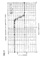
- inductance value in the ordinary transformer, usually equipped with the core reaches a saturated value (corresponding to the inductance value of a core-less transformer), at a certain electric current value, as shown in FIG. 11 where inductance characteristic curves against electric current value are depicted.
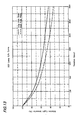
- FIG.12 depicts relations between initial permeability ( ⁇ i) of A type and B type cores used at a relatively lower temperature (below 100°C) and at a relatively higher temperature (below 150 °C) respectively, and temperature T (°C) so as to determine Curie temperatures in the respective core types.
- the Curie temperature of A type is 174°C for a lower temperature use and that of B type is 200°C for a higher temperature use. Since a ferrite core has a critical temperature (Curie temperature) where the core transforms from ferromagnetic to paramagnetic, the ferrite core with the higher Curie temperature should be used at a higher temperature range (100°C ⁇ 200°C).
- the core with Curie temperature above 200 °C should be selected for the starting transformer from a safety point, since heat from the lamp raises the temperature of the core up to ca. 150°C when a starting circuit is arranged in a lamp socket due to a short distance between the lamp and the core.
- the higher Curie temperature of the core is, the lower an initial permeability ( ⁇ i) of the core is (i.e. a lower inductance value when coil turns are kept constant), which means lower performance.
- ⁇ i initial permeability
- ⁇ i initial permeability
- the core When ferrite type cores are molded by an epoxy resin etc. for insulation, fatal defects such as ruptures or cracks are sometimes formed due to a shrinkage difference between the core and the molded resin.
- the core In order to avoid the above-mentioned defects caused by the shrinkage of the molded resin, the core has to be closed in a bobbin etc. or the core with a simple shape (round or rectangular rod etc.) has to be employed.
- the present invention is carried out in view of the above-mentioned problems so as to provide an inexpensively constituted, small sized and light weighed device free from breakage due to vibrations and impacts.
- the device attains electrical and structural connections simultaneously between high voltage electrodes and coils equipped in a starting transformer.
- the present invention also provides a starting device for discharge lamp having a function where a power is supplied only when the lamp is mounted.
- the starting device for discharge lamp is constituted as follows:
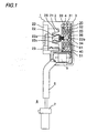
- FIG.1 is a cross sectional view depicting a constitution of a first embodiment according to the present invention.
- FIG.2 is an enlarged view of the main portion of FIG. 1.
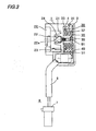
- FIG.3 is a cross sectional view depicting a constitution of a second embodiment according to the present invention.
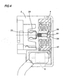
- FIG.4 is an enlarged view of the main portion of FIG.3.
- FIGs.5A to 5D show a constitution of a third embodiment having a direct coupler according to the present invention.
- FIG.5A is a front view.
- FIG.5B is a side view.
- FIG.5C is a cross sectional view along the B-B line in FIG.5A.
- FIG.5D is a back view with socket case removed.
- FIGs.6A to 6C show a constitution of a fourth embodiment according to the present invention.
- FIG.6A is a front view.
- FIG.5B is a cross sectional view along A-A line in FIG.6A.
- FIG.6C is a cross sectional view with a lamp base fitted in the socket shown in FIG.6B.
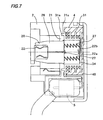
- FIG.7 is an enlarged view of FIG.6B.
- FIGs.8A and 8B show a constitution of a fifth embodiment according to the present invention.
- FIG.8A is a front view.
- FIG.8B is a side view.
- FIGs.9A and 9B show cross sectional views along line C-C in FIG.8A.
- FIG.9A is a view with a socket case removed.
- FIG.9B is a view with the socket case fitted.
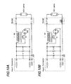
- FIGs.10A and 10B show starting circuit diagrams.
- FIG.10A is a circuit diagram employed in the first, second, third and fifth embodiments.
- FIG10B is a circuit diagram employed in the fourth embodiment.
- FIG.11 depicts inductance characteristic curves against electric current of starting transformers with/without core.
- FIG.12 depicts initial permeability curves of ferrite cores against temperature (Curie point determination curve).
- FIG.13 depicts HID lamp intensity curves against duration in relation to pulse widths.
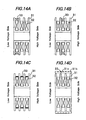
- FIGS.14A to 14D show winding manners in primary and secondary coils.
- FIGS.14A to 14D show a first, a second, a third and a fourth methods respectively.
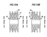
- FIGS.15A and 15B show winding manners in secondary coils.
- FIG.15A shows a manner of the equal winding turns in each section of the bobbin.
- FIG.15B shows a manner of decreased winding turns toward a high voltage side in the bobbin.
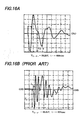
- FIGs.16A and 16B show transient curves of starting pulses.
- FIG.16A shows a curve of the present embodiments.
- FIG.16B shows a curve of the conventional starting device.
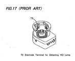
- FIG.17 shows a conventional lamp socket fitted with check terminals (detecting terminals) so as to detect whether the lamp is mounted or not.
- FIG.1 to FIG.16A Hereinafter detailed description of embodiments according to the present invention is explained by referring to FIG.1 to FIG.16A.
- the first embodiment according to the present invention shown in FIG.1 and FIG.2 is explained.
- This embodiment relates to a starting device for lamp lighting equipped in a lamp lighting device for an HID lamp.
- the lamp lighting device includes power sources for the HID lamp and for a trigger element to generate a starting pulse etc. equipped in a main body (not shown) of the lamp lighting device.
- the starting device for lamp lighting is consisted of structural members such as parts for starting, an HID lamp socket etc..
- the main body of the lamp lighting device and the starting device for lamp lighting is electrically connected between a connector 7 equipped to the starting device for lamp lighting via a harness 6 and a direct coupler equipped to the main body of the lightning device.
- a socket case 2 of a starting device 1 for lamp lighting for car use has a high voltage electrode 22 and a GND (grounding) electrode 23 formed by an insert molding or a direct insertion.
- Protruded portions 2a (quantity varies case by case) formed on the socket case 2 are fitted in cutout openings 3a formed on a rear socket case 3. (See FIG.5B.)
- An insulating wall 28 for insulation between the high voltage electrode 22 and the GND electrode 23 is formed, since a voltage between them reaches up to 20-odd kV.
- a high voltage leading electrode led out from a high voltage lamp receiving electrodes 22a of the high voltage electrode 22 surrounded by the insulating wall 28 is connected to a screw electrode 61.
- the screw electrode 61 extends thorough a separating wall 21 of the socket to a starting transformer accommodating space 4, namely to a center of the transformer, a core-less portion 34 (a hole accommodating a leading electrode 22c of the high voltage electrode 22 with a circular or rectangular cross-section of 1 to 10mm in diameter).
- a high voltage transformer connecting electrode 22b formed at the end of the screw electrode is connected to a leading wire 36 at high voltage side a secondary coil 32.
- a female screw is formed while at one end of the screw electrode 61 built in the core-less portion of a bobbin 31 a male screw is formed.
- the leading wire 36 at high voltage side is connected to the other end of the electrode 61 by a welding or a high temperature soldering method.
- a coil 35 having a primary coil 33 and the secondary coil 32 is fixed by mating with the above-mentioned female screw formed on the high voltage electrode 22.
- a power output of a starting transformer 30 from the high voltage electrode 22 is attained via the above-explained mated screws (made of conductive materials). In other words the fixing (holding the starting transformer 30) and electrical connection are attained simultaneously.
- the starting transformer 30 is consisted of the bobbin 31 (having a circular cross section in accordance with a geometry of the socket; Coil winding portions with a circular cross section are employed from a point of winding efficiency. Winding portions are divided into 3 to 6 sections.) in which the secondary coil 32 (100 to 400 turns, with 0.1 to 1.0mm wire in diameter, in experiments 300 turns and 0.3mm in diameter are employed.) is evenly wound around each winding section or more turns at a low voltage side than a high voltage side (See FIG.15B where insulating property is improved by gradated turns.) A distributed capacity of the secondary coil 32 is increased by divided turns explained above.
- the peak value can be decreased (to around limited value 20kV) by increasing the pulse width. Namely, a boosted voltage ratio (turning number of primary coil/turning number of secondary coil) can be kept lower. As a result advantages such as obtaining a small sized transformer and an efficient transformer with less copper loss are attained by decreased turning number of the secondary coil.
- the distributed capacity of the secondary coil with one rowed non-divided turn is ca. 0.001pF, on condition that the turning number is kept constant (a starting circuit constant is kept as the same value by employing a flat wire with layered winding due to a dimensional restriction of the bobbin).
- the starting pulse width is ca. 0.2 ⁇ sec and shows a steep starting curve. (See FIG.16A and 16B.)
- a wire with a circular cross section is wound in stead of a wire with a rectangular cross section considering a winding efficiency.
- the wire with the circular section has the lowest copper loss when a cross sectional area and the number of the turn are kept constant due to the fact that the outer diameter of the wire, namely, a length of the wound wire amounts to the shortest.
- a width of each divided section of the bobbin 31 is set several (an integer) times of the outer diameter (0.5 ⁇ 5.0mm) of the wire so as to attain the most efficient winding.
- a wall thickness between the sections is set 0.5 to 2.0mm.
- the primary coil 33 (1 to 10 turns, 0.1 to 1.0 in diameter.
- FIG.14D The another alternative shown in FIG.14D is constituted as follows:
- a bobbin case 31b is used as an insulating wall for preventing a leakage between the primary and secondary coils.
- On the primary coil a wire with a circular or rectangular cross-section is uniformly and sparsely wound around the outer diameter of the bobbin case 31b.
- the wire is wound densely on the center section of the bobbin case 31b.
- On the bobbin case a groove 31c is formed spirally on the outer surface of the bobbin case 31b so as to ensure firm winding of the coil.
- a leading wire 37 at a lower voltage side (see FIG.2) of the secondary coil 32 and two leading wires 38 (see FIG.5D) of the primary coil 33 are connected to three leading wire connecting points 50 (number is adjustable) formed on the bobbin 31. And these leading wires are lead to parts accommodating compartment 5 for the starting device via three slits 2b (see FIG.5D) so as to trail on the side wall of a starting transformer accommodating compartment 4.
- Parts for a starting circuit accommodated in the parts accommodating compartment 5 for the starting device are connected to a connecting board 29 (See FIG.5D) connected to the starting transformer and a harness assembly 8, by welding or high temperature soldering. (Since this portion is located near the HID lamp so that the ambient temperature reaches ca. 150 °C, a low temperature solder usually employed in organic circuit boards is not suitable.)
- leading wires 37 and 38 are contacted with the starting transformer accommodating compartment 4 closely via a clip 51 in order to avoid these leading wires from contacting the coil 35 (particularly the secondary coil 32, to ensure insulation).
- the starting transformer 30 After accommodating the starting transformer in the accommodating compartment 4, only the starting transformer 30 is molded with a molding material. (an epoxy resin, a urethane resin, a silicon resin and the like) Sometimes the parts accommodating compartment 5 for starting device is molded after arranging parts for the starting circuit in it for ensuring insulation, protection against humidity and vibration, and a stable fixture of parts.
- a molding material an epoxy resin, a urethane resin, a silicon resin and the like
- a GND electrode 23 is connected to the parts accommodating compartment 5 for the starting device via inner portion of a separating wall 21 of the socket.
- the electrode is finally connected to the harness assembly 8, which leads to the main body of the starting apparatus via the inputting connector 7.
- a male screw is formed at the bottom portion of a high voltage electrode 22.
- a female screw is formed at one end of a screw electrode 61 built in the core-less portion 34 (a central portion of the bobbin 31, i.e., a central portion of the socket 20) of the bobbin 31. Since this constitution is quite the same as the embodiment 1 except that the male screw and the female screw are replaced each other, further detailed explanation is omitted.
- a leading wire 36 is welded to the other end (with no screw formed) of the screw electrode 61 to form as an electrode rod.
- An electrical connection between the main body of the starting device and starting device for lamp lighting is attained by connecting a direct coupler equipped on the main body of the starting device to a direct coupler 81 equipped on the starting device for lamp lighting, via a harness having a connector (not shown).
- Input terminals 82 (3 terminals +400V, -600V and GND in FIG.10A and 10B) equipped in the direct coupler 81 are metal electrodes formed in one pieced member (formed in the socket case 2 or 3 by an insert molding) combined with a HID-GND electrode and an electrode 23 at a low voltage side of the secondary coil 32 or formed in separated members. Since only this forming method of the metal electrodes is different from those of preceding embodiments 1 and 2, further detailed explanation is omitted.
- a high voltage electrode 22 is formed at a central axis of the bobbin 31 of the above-mentioned core-less transformer 30 in the device. It has an insulating wall 28, a portion of a movable high voltage electrode holder 26 with a circular or rectangular cross-section.
- the socket case 2 and the bobbin 31 are molded into one piece.
- the above-mentioned constitution realizes a smaller and lighter apparatus which attains simultaneous electrical and structural connections between the high voltage electrode 22 and the secondary coil 32 of the transformer 30 for preventing damages caused by vibrations and impacts etc..
- the movable high voltage electrode holder 26 equipped with a switch is used so as to prevent generating the starting pulse, when there are no or incomplete connections between the lamp and socket even if a power is applied between them.
- the movable high voltage electrode holder 26 is protruded by springs 27 (consisted of 1 to 4 springs or the like having spring property), where a switch comprised by one end 22a of the high voltage electrode 22 and a high voltage electrode 22b of the starting transformer functions as "off" (22a and 22b are apart from each other), as a result no starting pulses are generated even if power is applied.
- the movable high voltage electrode holder 26 is pushed into the core-less space 34 of the transformer 30 so that 22a contacts to 22b. (a state of "on") Due to the core-less space 34, the above-explained structure can be realized.
- the bobbin 31 has an opening on only one side facing the socket separating wall 21.
- FIGs.8A, 8B and FIGs.9A, 9B show a structure to reduce parts number and manufacturing cost, where the socket case 2 and the bobbin 31 are formed in one piece.
- the wall enclosing the starting transformer accommodating compartment 4, formed at the rear side of the socket 2 in the embodiments 1 to 4, is abolished so as to wind coil around the bobbin 31 even after assembling the socket and the bobbin together. Therefore the connecting line i.e. the parting line 9 between the socket cases 2 and 3 is formed at a different position from preceding embodiments. (Compare FIG.8A with FIG.5B.)
- a molding material 40 is poured via openings 41 (In FIG.8A, 4 circular openings are illustrated, but different number and shape are also employable.) formed in the vicinity of the insulating wall 28 of the socket case 2. In some cases, a vacuum casting method is employed to remove bubbles to ensure further insulation.
- Input powers supplied from the main body of the starting device are +400V, GND as main powers and -600V as a power for SG (spark gap), a trigger element for high voltage pulse.
- the SG having a break down point of 800kV is selected among SGs for car use having the break down points between 400V and 3kV.
- the power -600V is supplied to the starting device circuit via resistance (not shown) connected in series to the output terminal.
- a constant determining a pulse cycle (usually between 30 to 150Hz) is determined by applying 1kV (voltage between the two terminals -600V and 400V) to a circuit where the above-mentioned resistance (not shown) and a charging/discharging capacitor C2 are connected in series.
- FIG.11 an abscissa is electric current scale and an ordinate is inductance scale
- FIG.11 shows that in coils with core inductance value start decreasing from a certain electric current value (in this case 2.0A) and finally reach a constant value (saturated phenomena), in accordance with increasing electric current.
- the ambient temperature is raised (+100°C) the inductance value reaches the saturated phenomenon at a lower electric current value than that of the ordinary temperature (+25°C).
- the inductance keeps a constant value independent from changes of the electric current value and the ambient temperature.
- FIG.12 an abscissa is temperature scale and an ordinate is initial permeability scale
- initial permeability curves of cores (A and B types) against temperature for determining Curie point are plotted.
- Ni-ferrite cores are employed in both A and B types.
- a Curie point means a critical temperature where a magnetic property of a core changes from ferromagnetic to paramagnetic.
- the Curie point of the A type core is determined 174°C and that of the B type core is determined 200°C.
- a core with higher Curie point is favorable, but ⁇ i reciprocally decreases against the increased Curie point.
- a coil with more turns are needed to obtain a required inductance value when a core with higher Curie point is used.
- the coil occupies more space and results in a larger sized starting device.
- a resistance value in the coil is increased so that a power loss due to the increased resistance value is added to the circuit where the secondary coil N2 of the transformer T is directly connected to the power line +400V as shown in FIGs.10A and 10B.
- the coil with core-less structure employed in the present invention solves above-mentioned problems.
- the core-less structure according to the present invention has no electric current saturation and is not influenced by the ambient temperature, a smaller and lighter device can be realized.
- the following advantages are attained in producing the starting device for lamp lighting and its components.
- (a) Breakage of the device caused by vibrations and impacts etc. is prevented by arranging the starting transformer on the same central axis of the socket.
- (b) Life of the HID lamp is prolonged by employing divided winding around the bobbin of the transformer for increasing the distributed capacity.
- the device can be fitted to every type of cars by attaining various connecting methods between the main body of the lamp lighting device and the starting device for lamp lighting.
- the connecting structure employed screws in the terminal of the high voltage electrode and in the screw electrode connected to the secondary coil of the starting transformer.
Landscapes
- Circuit Arrangements For Discharge Lamps (AREA)
- Non-Portable Lighting Devices Or Systems Thereof (AREA)
Applications Claiming Priority (2)
| Application Number | Priority Date | Filing Date | Title |
|---|---|---|---|
| JP2000066434A JP2001257088A (ja) | 2000-03-10 | 2000-03-10 | 放電灯起動装置 |
| JP2000066434 | 2000-03-10 |
Publications (2)
| Publication Number | Publication Date |
|---|---|
| EP1135009A2 true EP1135009A2 (fr) | 2001-09-19 |
| EP1135009A3 EP1135009A3 (fr) | 2003-12-03 |
Family
ID=18585794
Family Applications (1)
| Application Number | Title | Priority Date | Filing Date |
|---|---|---|---|
| EP01100615A Withdrawn EP1135009A3 (fr) | 2000-03-10 | 2001-01-11 | Appareil d'amorçage d'une lampe à décharge |
Country Status (3)
| Country | Link |
|---|---|
| US (1) | US6404142B2 (fr) |
| EP (1) | EP1135009A3 (fr) |
| JP (1) | JP2001257088A (fr) |
Cited By (1)
| Publication number | Priority date | Publication date | Assignee | Title |
|---|---|---|---|---|
| DE102007025421A1 (de) * | 2007-05-31 | 2008-12-04 | Vogt Electronic Components Gmbh | Zündtransformator und Zündmodul |
Families Citing this family (9)
| Publication number | Priority date | Publication date | Assignee | Title |
|---|---|---|---|---|
| JP2001333434A (ja) * | 2000-05-19 | 2001-11-30 | Sony Corp | 画像処理装置および方法、並びに記録媒体 |
| US6624596B1 (en) * | 2000-08-17 | 2003-09-23 | Mitsubishi Denki Kabushiki Kaisha | Device for lighting discharge lamp |
| JP2003017283A (ja) * | 2001-06-29 | 2003-01-17 | Ushio Inc | 光源装置 |
| ITRM20020594A1 (it) * | 2002-11-25 | 2004-05-26 | Sisti Lighting S P A De | Dispositivo perfezionato per l'accensione e l'alimentazione |
| US7131183B2 (en) * | 2004-04-26 | 2006-11-07 | Ford Motor Company | Screw in high voltage housing terminal for ignition coil |
| JP4860546B2 (ja) * | 2007-05-23 | 2012-01-25 | ミネベア株式会社 | コイルボビンおよびその製造方法 |
| JP4541387B2 (ja) * | 2007-08-13 | 2010-09-08 | 株式会社小糸製作所 | 放電ランプ用ソケット |
| EP2725715B1 (fr) * | 2012-10-29 | 2018-12-12 | Optosys SA | Détecteur de proximité |
| ITRN20130039A1 (it) * | 2013-09-27 | 2015-03-28 | Demos Fuochi | Dispositivo di accensione per lampade a scarica. |
Citations (1)
| Publication number | Priority date | Publication date | Assignee | Title |
|---|---|---|---|---|
| JPH1050436A (ja) | 1996-08-02 | 1998-02-20 | Hirose Electric Co Ltd | ランプソケット |
Family Cites Families (10)
| Publication number | Priority date | Publication date | Assignee | Title |
|---|---|---|---|---|
| DE69007314T2 (de) * | 1989-04-04 | 1994-09-29 | Philips Nv | Schaltanordnung. |
| US4952847A (en) * | 1989-06-05 | 1990-08-28 | Lin Tieng Fu | Stable ignition means for fluorescent lamp or the like |
| US5072158A (en) * | 1990-10-16 | 1991-12-10 | Ilc Technology, Inc. | Silent lamp igniter |
| JPH08222380A (ja) | 1995-02-13 | 1996-08-30 | Matsushita Electric Ind Co Ltd | 自動車用高輝度放電灯点灯装置 |
| US6066921A (en) * | 1995-02-28 | 2000-05-23 | Matsushita Electric Works, Ltd. | Discharge lamp lighting device |
| JPH1035357A (ja) | 1996-07-19 | 1998-02-10 | Matsushita Electric Ind Co Ltd | 放電灯点灯装置 |
| EP0852455B1 (fr) * | 1996-12-07 | 2002-05-29 | NGK Spark Plug Co. Ltd. | Dispositif de commande de l'éclairage d'un véhicule |
| JP3632183B2 (ja) * | 1997-01-28 | 2005-03-23 | 東洋電装株式会社 | 放電灯ユニット |
| JPH118140A (ja) * | 1997-06-16 | 1999-01-12 | Ngk Spark Plug Co Ltd | 高圧トランス |
| JPH11260573A (ja) * | 1998-03-09 | 1999-09-24 | Toyo Denso Co Ltd | 車両用hid前照灯装置 |
-
2000
- 2000-03-10 JP JP2000066434A patent/JP2001257088A/ja not_active Withdrawn
-
2001
- 2001-01-02 US US09/754,233 patent/US6404142B2/en not_active Expired - Fee Related
- 2001-01-11 EP EP01100615A patent/EP1135009A3/fr not_active Withdrawn
Patent Citations (1)
| Publication number | Priority date | Publication date | Assignee | Title |
|---|---|---|---|---|
| JPH1050436A (ja) | 1996-08-02 | 1998-02-20 | Hirose Electric Co Ltd | ランプソケット |
Cited By (2)
| Publication number | Priority date | Publication date | Assignee | Title |
|---|---|---|---|---|
| DE102007025421A1 (de) * | 2007-05-31 | 2008-12-04 | Vogt Electronic Components Gmbh | Zündtransformator und Zündmodul |
| DE102007025421B4 (de) * | 2007-05-31 | 2009-07-30 | Vogt Electronic Components Gmbh | Zündtransformator und Zündmodul |
Also Published As
| Publication number | Publication date |
|---|---|
| JP2001257088A (ja) | 2001-09-21 |
| US6404142B2 (en) | 2002-06-11 |
| US20010020824A1 (en) | 2001-09-13 |
| EP1135009A3 (fr) | 2003-12-03 |
Similar Documents
| Publication | Publication Date | Title |
|---|---|---|
| EP0886286B1 (fr) | Transformateur à haute tension et dispositif d'éclairage à lampe pour véhicule l'utilisant | |
| US6404142B2 (en) | Starting device for discharge lamp | |
| US7528693B2 (en) | Transformer and starting device having a transformer, and high pressure discharge lamp having a transformer | |
| US8193891B2 (en) | High voltage transformer with space-saving primary windings | |
| KR100402387B1 (ko) | 방전등 점등장치 | |
| US6479948B2 (en) | Starting device for discharge lamp | |
| US7696699B2 (en) | Lamp base for a high-pressure discharge lamp and corresponding high-pressure discharge lamp | |
| EP1135010A2 (fr) | Dispositif d'amorçage pour une lampe à décharge | |
| EP1146779A2 (fr) | Dispositif d' amorçage pour une lampe à décharge | |
| JP4506078B2 (ja) | 電磁装置および高電圧発生装置 | |
| JP4283363B2 (ja) | 放電ランプの始動装置及び放電ランプ | |
| JP3962889B2 (ja) | Hidランプ点灯装置 | |
| JP4415574B2 (ja) | 電磁装置及び高電圧発生装置 | |
| JP4535579B2 (ja) | 放電灯起動装置 | |
| JP2008544460A (ja) | ランプシステム及びガス放電ランプ | |
| KR100715387B1 (ko) | 방전등 점등 장치 | |
| JP2004207404A (ja) | 電磁装置及び高電圧発生装置 | |
| CN101116378A (zh) | 高压放电灯的灯座和高压放电灯 | |
| JPH04303907A (ja) | 高輝度放電灯トリガ用トランス | |
| JP2007129241A (ja) | 放電灯点灯装置 | |
| JP2005019611A (ja) | 電磁装置及び高電圧発生装置 | |
| JP2010218731A (ja) | 放電灯始動装置、並びにそれを用いたソケット及び車両用前照灯 | |
| JPH04307716A (ja) | 高輝度放電灯トリガ用トランス |
Legal Events
| Date | Code | Title | Description |
|---|---|---|---|
| PUAI | Public reference made under article 153(3) epc to a published international application that has entered the european phase |
Free format text: ORIGINAL CODE: 0009012 |
|
| AK | Designated contracting states |
Kind code of ref document: A2 Designated state(s): AT BE CH CY DE DK ES FI FR GB GR IE IT LI LU MC NL PT SE TR |
|
| AX | Request for extension of the european patent |
Free format text: AL;LT;LV;MK;RO;SI |
|
| PUAL | Search report despatched |
Free format text: ORIGINAL CODE: 0009013 |
|
| AK | Designated contracting states |
Kind code of ref document: A3 Designated state(s): AT BE CH CY DE DK ES FI FR GB GR IE IT LI LU MC NL PT SE TR |
|
| AX | Request for extension of the european patent |
Extension state: AL LT LV MK RO SI |
|
| RIC1 | Information provided on ipc code assigned before grant |
Ipc: 7H 01R 13/629 B Ipc: 7H 01R 33/46 B Ipc: 7H 01F 27/40 B Ipc: 7H 05B 41/04 A |
|
| 17P | Request for examination filed |
Effective date: 20040115 |
|
| AKX | Designation fees paid |
Designated state(s): DE FR GB |
|
| RBV | Designated contracting states (corrected) |
Designated state(s): DE FR GB |
|
| 17Q | First examination report despatched |
Effective date: 20050209 |
|
| STAA | Information on the status of an ep patent application or granted ep patent |
Free format text: STATUS: THE APPLICATION HAS BEEN WITHDRAWN |
|
| 18W | Application withdrawn |
Effective date: 20051129 |