EP1135565B1 - Triangulierte holzbauweisen, wie gitterträger, brücke, decken - Google Patents
Triangulierte holzbauweisen, wie gitterträger, brücke, decken Download PDFInfo
- Publication number
- EP1135565B1 EP1135565B1 EP99950859A EP99950859A EP1135565B1 EP 1135565 B1 EP1135565 B1 EP 1135565B1 EP 99950859 A EP99950859 A EP 99950859A EP 99950859 A EP99950859 A EP 99950859A EP 1135565 B1 EP1135565 B1 EP 1135565B1
- Authority
- EP
- European Patent Office
- Prior art keywords
- planks
- reinforcement
- wooden
- beams
- panel
- Prior art date
- Legal status (The legal status is an assumption and is not a legal conclusion. Google has not performed a legal analysis and makes no representation as to the accuracy of the status listed.)
- Expired - Lifetime
Links
- 230000002787 reinforcement Effects 0.000 claims abstract description 25
- 230000003014 reinforcing effect Effects 0.000 claims description 11
- 230000000063 preceeding effect Effects 0.000 claims 1
- 238000010008 shearing Methods 0.000 abstract description 5
- 239000007787 solid Substances 0.000 abstract description 4
- 239000011120 plywood Substances 0.000 abstract description 3
- 239000002023 wood Substances 0.000 description 8
- 238000005452 bending Methods 0.000 description 7
- 238000004519 manufacturing process Methods 0.000 description 6
- 239000000463 material Substances 0.000 description 3
- 230000000712 assembly Effects 0.000 description 2
- 238000000429 assembly Methods 0.000 description 2
- 150000001875 compounds Chemical class 0.000 description 2
- 238000010276 construction Methods 0.000 description 2
- 229910052751 metal Inorganic materials 0.000 description 2
- 239000002184 metal Substances 0.000 description 2
- 229910052782 aluminium Inorganic materials 0.000 description 1
- XAGFODPZIPBFFR-UHFFFAOYSA-N aluminium Chemical compound [Al] XAGFODPZIPBFFR-UHFFFAOYSA-N 0.000 description 1
- 230000006835 compression Effects 0.000 description 1
- 238000007906 compression Methods 0.000 description 1
- 239000000470 constituent Substances 0.000 description 1
- 230000001419 dependent effect Effects 0.000 description 1
- 238000010586 diagram Methods 0.000 description 1
- 238000001035 drying Methods 0.000 description 1
- 239000000835 fiber Substances 0.000 description 1
- 238000000034 method Methods 0.000 description 1
- 238000005457 optimization Methods 0.000 description 1
- 210000004258 portal system Anatomy 0.000 description 1
- 238000005728 strengthening Methods 0.000 description 1
Images


Classifications
-
- E—FIXED CONSTRUCTIONS
- E04—BUILDING
- E04C—STRUCTURAL ELEMENTS; BUILDING MATERIALS
- E04C3/00—Structural elongated elements designed for load-supporting
- E04C3/02—Joists; Girders, trusses, or trusslike structures, e.g. prefabricated; Lintels; Transoms; Braces
- E04C3/12—Joists; Girders, trusses, or trusslike structures, e.g. prefabricated; Lintels; Transoms; Braces of wood, e.g. with reinforcements, with tensioning members
- E04C3/16—Joists; Girders, trusses, or trusslike structures, e.g. prefabricated; Lintels; Transoms; Braces of wood, e.g. with reinforcements, with tensioning members with apertured web, e.g. trusses
-
- E—FIXED CONSTRUCTIONS
- E04—BUILDING
- E04C—STRUCTURAL ELEMENTS; BUILDING MATERIALS
- E04C3/00—Structural elongated elements designed for load-supporting
- E04C3/02—Joists; Girders, trusses, or trusslike structures, e.g. prefabricated; Lintels; Transoms; Braces
- E04C3/12—Joists; Girders, trusses, or trusslike structures, e.g. prefabricated; Lintels; Transoms; Braces of wood, e.g. with reinforcements, with tensioning members
- E04C3/17—Joists; Girders, trusses, or trusslike structures, e.g. prefabricated; Lintels; Transoms; Braces of wood, e.g. with reinforcements, with tensioning members with non-parallel upper and lower edges, e.g. roof trusses
Definitions
- Wood is a material widely used in construction, and with which it is possible to make a whole series of load-bearing systems with properties clean mechanics, and allowing to support all levels and all types of loads.
- the different wooden load-bearing systems are posts and beams, triangulated systems, articulated systems, portal frames, beam grids, shells and elements functioning as plates.
- the triangulated system is the most universal, because it allows to take up very heavy loads, while being very simple to build. As an indication, the triangulated system is causing farm systems used in Europe and which have been developed since the 12th century and are still used today.
- the triangulated wooden systems are to be classified into two main families illustrated schematically by Figures 1 to 6 attached.
- the first system called “parallel frame system”, illustrated by Figures 1 to 3, is used for example for bridges or floor systems horizontal.
- the assembly thus produced rests on at least two supports (5). To reduce internal efforts, we can sometimes add support inside the system, but this is not always possible.
- the “triangle-shaped” systems as illustrated in FIGS. 4 to 6, are generally used to make roof structures and allow give the slope to the latter.
- Such assemblies rest on supports (5) arranged at each end the tie rod (7).
- the invention relates to this technical sector and relates more particularly to the realization of a new type of load-bearing system both with parallel members in the shape of a triangle, which, while having mechanical characteristics high, reduce production costs and is easily adaptable depending on the characteristics desired for each particular application (load to be supported, system dimensions ).
- the first node in the case of frames, links, tie rods (7), crossbowmen (6) and diagonals (8), is made with wooden parts solid or glued laminated wood, depending on the section needs and the knot is made by means of metal fittings for systems with high inertia, or even sometimes simply glued for lower inertia floor systems.
- a system with triangulated wooden structures, with frames parallel or triangle-shaped, for the production of frames, bridges and floors consists of beams forming between them junction zones and being constructed at from at least three boards, a central board forming a core and at least two side planks, all planks having the same thickness and being nailed to each other.
- the system is characterized in that the board center is offset from the ends of the two side boards, so that form mortises at this level, which include, at the level of the junction zones between the beams, a reinforcement panel positioned in the core, the shear surfaces of the reinforcement panel corresponding to the lateral surfaces of the two boards lateral at each junction zone, said reinforcing panel being in microlame or plywood.
- the solution according to the invention also makes it possible to reduce the bending moments in the joint since the reinforcement itself absorbs the bending since the “plate” type reinforcement has a very high rigidity since he works in both directions of his plan.
- Such reinforcement allows resume the shear forces of the internal beams, such as for example the shear between a compressed diagonal and a tensioned beam, at the level of the node, by mechanically relieving the external beam accordingly.
- This reinforcement can be more or less isotropic depending on the forces to be resume.
- the beams involved in the realization of a system according to the invention will consist of at least three layers, the reinforcements being therefore positioned at the level of the central layer, which allows a double shearing of the through nails relative to the reinforcement which would be exposed to outside the system, as is often the case.
- the two end posts will also consist of three layers nailed together, the central layer not being constituted by a board, but by a wooden structural element of the microlame type extending beyond the ends of the two lateral boards as well as towards the inside of the structure in order to form tenons capable of receiving the mortises of the other beams of the system.
- the reinforcement can either be positioned only in the central position, or can be doubled and then being positioned in the layers (two) and (four).
- the structural system according to the invention is characterized in that the number of boards used in the constitution of each layer is odd and is greater than three, five for example, a reinforcement being positioned at each node in the even layers.
- the ribs or reinforcing plates are arranged at least at the support zones where the forces are maximum. Possibly, the internal forces being lower in the uprights and diagonals, the assemblies of the triangulated system can possibly be carried out conventionally by a simple assembly of the “tenon / mortise” type, the tenon being formed by the offset towards the outside of the board. central, and the mortise by the spacing between two elementary boards constituting the central board. It is however advantageous to also reinforce these zones by fitting a reinforcing plate at this level making it possible to directly absorb the shear between the compressed diagonal and the tensioned post or vice versa.
- the reinforcement or rib is fixed over its entire perimeter to other beams (tie rods, rafters, uprights or diagonals) by simple nailing, which is the most economical solution and which presents as advantage of being semi-rigid allowing the entire plate to be stressed, after deformation of the edge connectors.
- the elementary planks entering the constitution of each beam are massive planks whose section is generally between 10 and 30 cm in width for 3 to 8 cm in thickness.
- the length of said boards can be variable and depends on the systems to achieve and will for example be between four to eight meters.
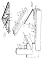
- Such a system is of the type shown in FIG. 1.
- each beam consists of three elementary planks (10,11,12).
- the board intermediate (10) is offset from the ends of the side boards (11,12), and this, in this case, from a distance of about 50 cm thus allowing to provide at each end a recess forming a mortise (13).
- the diagonals (4) are made in a similar way from three boards and also have a mortise at their end.
- the internal uprights (M) are made in a similar way.
- the post (3) consists of two external planks (14) between which is inserted, over its entire length, a third board (15), intended to constitute the reinforcement of the panel type positioned in the core and which is formed by a microlame type structural panel having a thickness of 4 cm, the external boards (14) also having a thickness of 4 cm.
- This panel (15) projects at each end relative to the boards lateral (14,15) and forms a tenon having a height of 20 cm corresponding therefore the width of the boards (10,11,12) constituting the dies, and a length of 50 cm corresponding to the length of the mortise (13) provided at the ends of the beams constituting the dies.
- the reinforcing plate (15) extends over the entire system surface at each end at the supports (5), it could possibly consider making reinforcing plates only at each of the ends, the central part of the post (3) then being constituted by an additional board, set back from the ends of the boards side.
- connection is also made by inserting, at the junction zones, additional plates.
- Each of the elements therefore comprises at the junction zone a mortise intended to receive the reinforcing element.
- the assembly could be carried out without reinforcing element and the ends of the uprights (M) and diagonals (4) will have the shape of a tenon formed by the offset towards the outside of the central board while the dies or members (1,2) will have, along their length, mortises obtained in producing the internal board (10) by means of elementary boards spaced apart each other of a length corresponding to the tenon of the ends.
- FIGS. 9 and 10 Such an embodiment according to the invention is illustrated by the FIGS. 9 and 10 and corresponds to the general structure which is the subject of FIG. 4, it being understood that structures of the type illustrated by figures 5 and 6.
- This structure is also produced from boards having a cross section 20 cm x 4 cm.
- all of the beams entering the constitution of such a system consists of three elementary boards (21,22,23) nailed together.
- the central plate (21) is, at the ends, set back from the ends of the side boards, so forming at this level a mortise (24) capable of receiving a reinforcing element.
- the reinforcement insert (20) is triangular in shape, the base of which has a length of 700 mm and a height of 400 mm.
- mortises are provided at each end of the diagonals (8) and uprights (9), and this by offset of the inner layer relative to the ends of the side boards, the mortise in the tie rod (7) being, in turn, obtained by making the central board from elementary boards spaced from each other other.
- connection between the different constituents is obtained by nailing and reinforcements (20) of the nodes whose junction is made from a panel consisting of a wooden structural element of the type microblades having a thickness of 4 cm.
- the reinforcement panels positioned in the core of each beam make it possible to increase the surface of the nailing zones reinforcing the structure.
- Such an interfaced panel also regulates the bending moments in the articulation on the dies in the case of a system with parallel members or triangulated since the reinforcement itself absorbs bending; it thus absorbs the shear between the internal beams arriving in the node by relieving mechanically the external beam.
Landscapes
- Engineering & Computer Science (AREA)
- Architecture (AREA)
- Life Sciences & Earth Sciences (AREA)
- Wood Science & Technology (AREA)
- Civil Engineering (AREA)
- Structural Engineering (AREA)
- Rod-Shaped Construction Members (AREA)
- Joining Of Building Structures In Genera (AREA)
- Panels For Use In Building Construction (AREA)
- Floor Finish (AREA)
- Bridges Or Land Bridges (AREA)
Claims (4)
- System mit dreieckförmig angeordneten Strukturen aus Holz, mit parallelem oder dreieckförmigem Fachwerk für die Herstellung von Dachgebälken, Dachböden und Decken, bestehend aus Balken (1, 2, 3, 4, 6, 7, 8, 9), welche zwischen einander Anschlusszonen bilden und aus wenigstens aus drei Brettern (10, 11, 12, 21, 22, 23) hergestellt sind, nämlich einem zentralen Brett, das den Kern (10, 21) bildet, und mindestens zwei Seitenbrettern (11, 12, 22, 23), wobei alle Bretter (10, 11, 12, 21, 22, 23) die gleiche Dicke haben und miteinander durch Nägel verbunden sind, dadurch gekennzeichnet, dass:das zentrale Brett (10, 21) derart gegenüber den Enden der beiden Seitenbretter (11, 12, 22, 23) versetzt ist, dass in diesem Bereich Ausklinkungen (13, 24) gebildet werden, welche im Bereich der Anschlusszonen zwischen den Balken (1, 2, 3, 4, 6, 7, 8, 9) ein im Kern angeordnetes Versteifungsbrett (15, 20) aufnimmt, wobei die Schneidflächen des Versteifungsbretts (15, 20) den Seitenflächen der beiden Bretter (11, 12, 22, 23) im Bereich jeder Anschlusszone entsprechen und das Versteifungsbrett aus lamelliertem Holz oder Sperrholz besteht.
- System nach Anspruch 1, dadurch gekennzeichnet, dass das zentrale Brett (10, 21) aus Einzelbrettern besteht, die aneinander grenzend oder derart beabstandet angeordnet sind, dass sie einen Ausklinkung bilden, die eine plattenartige Verstärkung aufnehmen kann.
- System nach Anspruch 1 oder 2, dadurch gekennzeichnet, dass die Anzahl der Bretter, die jeden Balken bilden, ungerade und größer als drei ist, wobei im Bereich jedes Knotens in den geradzahligen Schichten eine Verstärkung angeordnet ist.
- System nach einem der vorhergehenden Ansprüche, dadurch gekennzeichnet, dass die Verstärkungsplatte bestehend aus einer Holzstruktur-Platte das zentrale Brett (15) der Balken bildet, welche die Balken, welche die Pfosten (3) eines Systems mit dreieckförmig angeordneten Strukturen mit parallelem Fachwerk bilden.
Applications Claiming Priority (3)
| Application Number | Priority Date | Filing Date | Title |
|---|---|---|---|
| FR9815456A FR2786796B1 (fr) | 1998-12-03 | 1998-12-03 | Systemes structurels triangules en bois, tels que charpentes , ponts, planchers |
| FR9815456 | 1998-12-03 | ||
| PCT/FR1999/002627 WO2000032891A1 (fr) | 1998-12-03 | 1999-10-28 | Systemes structurels triangules en bois, tels que charpentes, ponts, planchers |
Publications (2)
| Publication Number | Publication Date |
|---|---|
| EP1135565A1 EP1135565A1 (de) | 2001-09-26 |
| EP1135565B1 true EP1135565B1 (de) | 2003-09-03 |
Family
ID=9533699
Family Applications (1)
| Application Number | Title | Priority Date | Filing Date |
|---|---|---|---|
| EP99950859A Expired - Lifetime EP1135565B1 (de) | 1998-12-03 | 1999-10-28 | Triangulierte holzbauweisen, wie gitterträger, brücke, decken |
Country Status (9)
| Country | Link |
|---|---|
| US (1) | US20020124521A1 (de) |
| EP (1) | EP1135565B1 (de) |
| JP (1) | JP2002531731A (de) |
| AT (1) | ATE248965T1 (de) |
| AU (1) | AU3791000A (de) |
| BR (1) | BR9915894A (de) |
| DE (1) | DE69911055T2 (de) |
| FR (1) | FR2786796B1 (de) |
| WO (1) | WO2000032891A1 (de) |
Families Citing this family (8)
| Publication number | Priority date | Publication date | Assignee | Title |
|---|---|---|---|---|
| FR2831906B1 (fr) | 2001-11-06 | 2004-09-24 | Jean Luc Sandoz | Structure renforcee en bois, charpente, batiment ainsi equipe et procede de fabrication |
| JP4504781B2 (ja) * | 2004-10-22 | 2010-07-14 | 株式会社モリタホールディングス | 消防用梯子 |
| US20070227095A1 (en) * | 2006-03-16 | 2007-10-04 | Peter Warren Hubbe | Separated Member Wood Framing |
| FR2932828B1 (fr) * | 2008-06-21 | 2010-06-25 | Tecsan Sarl | Sous-ensemble de charpente de support d'une couverture de toit et charpente en comportant application. |
| JP5464350B2 (ja) * | 2010-03-03 | 2014-04-09 | 国立大学法人秋田大学 | プレストレス木床版を用いた木橋 |
| JP5856646B2 (ja) * | 2014-04-30 | 2016-02-10 | クリ英ター永和株式会社 | 木製トラス梁ユニット、及びその設置工法 |
| JP7426253B2 (ja) * | 2020-02-18 | 2024-02-01 | 三井住友建設株式会社 | トラス梁 |
| ES2957745B2 (es) * | 2021-12-23 | 2025-04-10 | Univ Del Pais Vasco / Euskal Herriko Unibertsitatea | Conjuntos de madera para uniones de estructura y estructura que contiene al menos uno o mas conjuntos |
Family Cites Families (8)
| Publication number | Priority date | Publication date | Assignee | Title |
|---|---|---|---|---|
| US2886857A (en) | 1953-12-14 | 1959-05-19 | Hyresgaesternas Sparkasse Och | Wooden beam constructions |
| FR1541776A (fr) * | 1967-08-30 | 1968-10-11 | Ferme de charpente | |
| CH467402A (de) * | 1967-12-15 | 1969-01-15 | Ringbau Ag | Gurt-Streben- Verbindung für Holz-Gitterträger |
| FR2303128A1 (fr) * | 1975-03-07 | 1976-10-01 | Habitat Communaute Travail | Perfectionnements aux procedes pour l'assemblage des elements de charpente |
| FR2367883A1 (fr) * | 1976-10-12 | 1978-05-12 | Uhalde Bernier Sa | Perfectionnements aux procedes de fabrication de charpentes en materiaux ligneux, procede tcp |
| DE3006404A1 (de) * | 1980-02-21 | 1981-08-27 | Streif Ohg, 5461 Vettelschoss | Geleimter holzfachwerk-schalungstraeger |
| FI69498C (fi) | 1983-10-07 | 1986-02-10 | Metsaeliiton Teollisuus Oy | Fog foer sammanfogning av traebalkar och fogens anvaendning vi takstolskonstruktionen |
| DE3910027A1 (de) | 1989-03-28 | 1990-10-04 | Wilhelm Patt | Vorgefertigtes, freitragendes dachelement fuer den hochbau |
-
1998
- 1998-12-03 FR FR9815456A patent/FR2786796B1/fr not_active Expired - Fee Related
-
1999
- 1999-10-28 WO PCT/FR1999/002627 patent/WO2000032891A1/fr not_active Ceased
- 1999-10-28 DE DE69911055T patent/DE69911055T2/de not_active Expired - Fee Related
- 1999-10-28 JP JP2000585512A patent/JP2002531731A/ja not_active Withdrawn
- 1999-10-28 EP EP99950859A patent/EP1135565B1/de not_active Expired - Lifetime
- 1999-10-28 BR BR9915894-9A patent/BR9915894A/pt active Search and Examination
- 1999-10-28 AU AU37910/00A patent/AU3791000A/en not_active Abandoned
- 1999-10-28 AT AT99950859T patent/ATE248965T1/de not_active IP Right Cessation
-
2001
- 2001-05-25 US US09/866,432 patent/US20020124521A1/en not_active Abandoned
Also Published As
| Publication number | Publication date |
|---|---|
| BR9915894A (pt) | 2001-08-21 |
| EP1135565A1 (de) | 2001-09-26 |
| AU3791000A (en) | 2000-06-19 |
| ATE248965T1 (de) | 2003-09-15 |
| US20020124521A1 (en) | 2002-09-12 |
| WO2000032891A1 (fr) | 2000-06-08 |
| FR2786796A1 (fr) | 2000-06-09 |
| DE69911055T2 (de) | 2004-04-01 |
| FR2786796B1 (fr) | 2001-01-26 |
| DE69911055D1 (de) | 2003-10-09 |
| JP2002531731A (ja) | 2002-09-24 |
Similar Documents
| Publication | Publication Date | Title |
|---|---|---|
| EP3102755B1 (de) | Verbundwand für gebäude sowie gebäudeeinheiten mit mindestens einer derartigen verbundwand | |
| FR2670523A1 (fr) | Element prefabrique de mur en beton arme. | |
| EP1135565A1 (de) | Triangulierte holzbauweisen, wie gitterträger, brücke, decken | |
| WO1998054418A1 (fr) | Ossature de batiment | |
| FR2656020A1 (fr) | Assemblage par emboitement de deux profiles a section droite en z, notamment pour la realisation d'une panne, d'une lisse ou d'un support de plancher. | |
| EP1451420B1 (de) | Holzverstärkte struktur, rahmen und mit einer solchen struktur ausgestattetes gebäude sowie herstellungsverfahren dafür | |
| EP2108758B1 (de) | Verfahren zur herstellung eines strukturelementes | |
| EP0440567A1 (de) | Einzelne und doppelte Träger und Pfosten, bestehend aus der Zusammensetzung von Z-Trägern, die insbesondere die Realisierung eines Rahmens oder einer Kniestütze für den Bau eines Gebäudes erlauben | |
| FR2760478A1 (fr) | Element de construction de type poutre | |
| EP0393740B1 (de) | Steife Knoten für Holzkonstruktionen und dreidimensionale Holzgerüste und mit solchen Knoten versehene Konstruktionen | |
| FR2846681A1 (fr) | Structure porteuse modulaire | |
| FR2940337A1 (fr) | Poutrelle metallique pour la fabrication de planchers | |
| FR3093119A1 (fr) | Structure métallique modulaire | |
| FR2862076A1 (fr) | Poutre de longue portee destinee a constituer un element porteur d'une superstructure modulaire | |
| FR3070407A1 (fr) | Structure porteuse a base de poutres de fort elancement et procede de montage associe | |
| EP0220256B1 (de) | Lamelliertes bauelement | |
| FR3145762A1 (fr) | Module de construction | |
| EP3317468A1 (de) | Verbundwand für eine konstruktion und konstruktionsanordnung mit mindestens einer solchen verbundwand | |
| FR2741100A1 (fr) | Combles d'une habitation, delimites par une charpente dont la structure permet un gain de volume utile, et procede de transformation de combles non amenageables en vue de les rendre habitables | |
| EP4062001A1 (de) | Modulare metallstruktur | |
| EP0260197A1 (de) | Stahlbetonbrücke mit integrierter Schalung | |
| EP1899544A1 (de) | Strukturbauelement aus glas | |
| FR2704886A1 (fr) | Elément de construction notamment en bois. | |
| EP1764452A1 (de) | Konstruktion mit einem vorgefertigten und vorbehandelten Gitterträger | |
| FR2536775A1 (fr) | Structure modulaire metallique pour charpente |
Legal Events
| Date | Code | Title | Description |
|---|---|---|---|
| PUAI | Public reference made under article 153(3) epc to a published international application that has entered the european phase |
Free format text: ORIGINAL CODE: 0009012 |
|
| 17P | Request for examination filed |
Effective date: 20010504 |
|
| AK | Designated contracting states |
Kind code of ref document: A1 Designated state(s): AT BE CH CY DE DK ES FI FR GB GR IE IT LI LU MC NL PT SE |
|
| 17Q | First examination report despatched |
Effective date: 20021016 |
|
| GRAH | Despatch of communication of intention to grant a patent |
Free format text: ORIGINAL CODE: EPIDOS IGRA |
|
| GRAS | Grant fee paid |
Free format text: ORIGINAL CODE: EPIDOSNIGR3 |
|
| GRAA | (expected) grant |
Free format text: ORIGINAL CODE: 0009210 |
|
| AK | Designated contracting states |
Kind code of ref document: B1 Designated state(s): AT BE CH CY DE DK ES FI FR GB GR IE IT LI LU MC NL PT SE |
|
| PG25 | Lapsed in a contracting state [announced via postgrant information from national office to epo] |
Ref country code: NL Free format text: LAPSE BECAUSE OF FAILURE TO SUBMIT A TRANSLATION OF THE DESCRIPTION OR TO PAY THE FEE WITHIN THE PRESCRIBED TIME-LIMIT Effective date: 20030903 Ref country code: IE Free format text: LAPSE BECAUSE OF FAILURE TO SUBMIT A TRANSLATION OF THE DESCRIPTION OR TO PAY THE FEE WITHIN THE PRESCRIBED TIME-LIMIT Effective date: 20030903 Ref country code: GB Free format text: LAPSE BECAUSE OF FAILURE TO SUBMIT A TRANSLATION OF THE DESCRIPTION OR TO PAY THE FEE WITHIN THE PRESCRIBED TIME-LIMIT Effective date: 20030903 Ref country code: FI Free format text: LAPSE BECAUSE OF FAILURE TO SUBMIT A TRANSLATION OF THE DESCRIPTION OR TO PAY THE FEE WITHIN THE PRESCRIBED TIME-LIMIT Effective date: 20030903 |
|
| REG | Reference to a national code |
Ref country code: GB Ref legal event code: FG4D Free format text: NOT ENGLISH |
|
| REG | Reference to a national code |
Ref country code: CH Ref legal event code: NV Representative=s name: BUGNION S.A. Ref country code: CH Ref legal event code: EP |
|
| REF | Corresponds to: |
Ref document number: 69911055 Country of ref document: DE Date of ref document: 20031009 Kind code of ref document: P |
|
| REG | Reference to a national code |
Ref country code: IE Ref legal event code: FG4D Free format text: FRENCH |
|
| PG25 | Lapsed in a contracting state [announced via postgrant information from national office to epo] |
Ref country code: LU Free format text: LAPSE BECAUSE OF NON-PAYMENT OF DUE FEES Effective date: 20031028 Ref country code: CY Free format text: LAPSE BECAUSE OF FAILURE TO SUBMIT A TRANSLATION OF THE DESCRIPTION OR TO PAY THE FEE WITHIN THE PRESCRIBED TIME-LIMIT Effective date: 20031028 |
|
| PG25 | Lapsed in a contracting state [announced via postgrant information from national office to epo] |
Ref country code: MC Free format text: LAPSE BECAUSE OF NON-PAYMENT OF DUE FEES Effective date: 20031031 Ref country code: BE Free format text: LAPSE BECAUSE OF NON-PAYMENT OF DUE FEES Effective date: 20031031 |
|
| PG25 | Lapsed in a contracting state [announced via postgrant information from national office to epo] |
Ref country code: SE Free format text: LAPSE BECAUSE OF FAILURE TO SUBMIT A TRANSLATION OF THE DESCRIPTION OR TO PAY THE FEE WITHIN THE PRESCRIBED TIME-LIMIT Effective date: 20031203 Ref country code: GR Free format text: LAPSE BECAUSE OF FAILURE TO SUBMIT A TRANSLATION OF THE DESCRIPTION OR TO PAY THE FEE WITHIN THE PRESCRIBED TIME-LIMIT Effective date: 20031203 Ref country code: DK Free format text: LAPSE BECAUSE OF FAILURE TO SUBMIT A TRANSLATION OF THE DESCRIPTION OR TO PAY THE FEE WITHIN THE PRESCRIBED TIME-LIMIT Effective date: 20031203 |
|
| PG25 | Lapsed in a contracting state [announced via postgrant information from national office to epo] |
Ref country code: ES Free format text: LAPSE BECAUSE OF FAILURE TO SUBMIT A TRANSLATION OF THE DESCRIPTION OR TO PAY THE FEE WITHIN THE PRESCRIBED TIME-LIMIT Effective date: 20031214 |
|
| NLV1 | Nl: lapsed or annulled due to failure to fulfill the requirements of art. 29p and 29m of the patents act | ||
| PG25 | Lapsed in a contracting state [announced via postgrant information from national office to epo] |
Ref country code: PT Free format text: LAPSE BECAUSE OF FAILURE TO SUBMIT A TRANSLATION OF THE DESCRIPTION OR TO PAY THE FEE WITHIN THE PRESCRIBED TIME-LIMIT Effective date: 20040203 |
|
| GBV | Gb: ep patent (uk) treated as always having been void in accordance with gb section 77(7)/1977 [no translation filed] |
Effective date: 20030903 |
|
| REG | Reference to a national code |
Ref country code: IE Ref legal event code: FD4D |
|
| BERE | Be: lapsed |
Owner name: *SANDOZ JEAN-LUC Effective date: 20031031 |
|
| PLBE | No opposition filed within time limit |
Free format text: ORIGINAL CODE: 0009261 |
|
| STAA | Information on the status of an ep patent application or granted ep patent |
Free format text: STATUS: NO OPPOSITION FILED WITHIN TIME LIMIT |
|
| 26N | No opposition filed |
Effective date: 20040604 |
|
| PGFP | Annual fee paid to national office [announced via postgrant information from national office to epo] |
Ref country code: DE Payment date: 20081010 Year of fee payment: 10 |
|
| PGFP | Annual fee paid to national office [announced via postgrant information from national office to epo] |
Ref country code: AT Payment date: 20080918 Year of fee payment: 10 |
|
| REG | Reference to a national code |
Ref country code: FR Ref legal event code: TP Ref country code: FR Ref legal event code: CL |
|
| PGFP | Annual fee paid to national office [announced via postgrant information from national office to epo] |
Ref country code: IT Payment date: 20081020 Year of fee payment: 10 |
|
| PG25 | Lapsed in a contracting state [announced via postgrant information from national office to epo] |
Ref country code: DE Free format text: LAPSE BECAUSE OF NON-PAYMENT OF DUE FEES Effective date: 20100501 |
|
| PG25 | Lapsed in a contracting state [announced via postgrant information from national office to epo] |
Ref country code: AT Free format text: LAPSE BECAUSE OF NON-PAYMENT OF DUE FEES Effective date: 20091028 |
|
| PG25 | Lapsed in a contracting state [announced via postgrant information from national office to epo] |
Ref country code: IT Free format text: LAPSE BECAUSE OF NON-PAYMENT OF DUE FEES Effective date: 20091028 |
|
| PGFP | Annual fee paid to national office [announced via postgrant information from national office to epo] |
Ref country code: CH Payment date: 20121019 Year of fee payment: 14 |
|
| REG | Reference to a national code |
Ref country code: CH Ref legal event code: PL |
|
| PG25 | Lapsed in a contracting state [announced via postgrant information from national office to epo] |
Ref country code: CH Free format text: LAPSE BECAUSE OF NON-PAYMENT OF DUE FEES Effective date: 20131031 Ref country code: LI Free format text: LAPSE BECAUSE OF NON-PAYMENT OF DUE FEES Effective date: 20131031 |
|
| REG | Reference to a national code |
Ref country code: FR Ref legal event code: PLFP Year of fee payment: 17 |
|
| PGFP | Annual fee paid to national office [announced via postgrant information from national office to epo] |
Ref country code: FR Payment date: 20151030 Year of fee payment: 17 |
|
| REG | Reference to a national code |
Ref country code: FR Ref legal event code: ST Effective date: 20170630 |
|
| PG25 | Lapsed in a contracting state [announced via postgrant information from national office to epo] |
Ref country code: FR Free format text: LAPSE BECAUSE OF NON-PAYMENT OF DUE FEES Effective date: 20161102 |