EP1135623B1 - Conduite flexible a enroulement de fil de forme en i - Google Patents
Conduite flexible a enroulement de fil de forme en i Download PDFInfo
- Publication number
- EP1135623B1 EP1135623B1 EP99936652A EP99936652A EP1135623B1 EP 1135623 B1 EP1135623 B1 EP 1135623B1 EP 99936652 A EP99936652 A EP 99936652A EP 99936652 A EP99936652 A EP 99936652A EP 1135623 B1 EP1135623 B1 EP 1135623B1
- Authority
- EP
- European Patent Office
- Prior art keywords
- wire
- pipe
- recesses
- wings
- vault
- Prior art date
- Legal status (The legal status is an assumption and is not a legal conclusion. Google has not performed a legal analysis and makes no representation as to the accuracy of the status listed.)
- Expired - Lifetime
Links
- 238000004804 winding Methods 0.000 title claims abstract description 15
- 229910052751 metal Inorganic materials 0.000 claims abstract description 12
- 239000002184 metal Substances 0.000 claims abstract description 12
- 238000007789 sealing Methods 0.000 claims description 10
- 230000001681 protective effect Effects 0.000 claims 1
- 238000009434 installation Methods 0.000 description 6
- 229910000831 Steel Inorganic materials 0.000 description 4
- 239000012530 fluid Substances 0.000 description 4
- 239000010959 steel Substances 0.000 description 4
- 238000004519 manufacturing process Methods 0.000 description 3
- 239000003208 petroleum Substances 0.000 description 3
- 229920000642 polymer Polymers 0.000 description 3
- 229910052782 aluminium Inorganic materials 0.000 description 2
- XAGFODPZIPBFFR-UHFFFAOYSA-N aluminium Chemical compound [Al] XAGFODPZIPBFFR-UHFFFAOYSA-N 0.000 description 2
- 238000005452 bending Methods 0.000 description 2
- 238000005096 rolling process Methods 0.000 description 2
- 230000003068 static effect Effects 0.000 description 2
- 241000219357 Cactaceae Species 0.000 description 1
- 239000004809 Teflon Substances 0.000 description 1
- 229920006362 Teflon® Polymers 0.000 description 1
- 230000015572 biosynthetic process Effects 0.000 description 1
- 230000000295 complement effect Effects 0.000 description 1
- 230000007423 decrease Effects 0.000 description 1
- 238000009826 distribution Methods 0.000 description 1
- 239000007789 gas Substances 0.000 description 1
- 230000005484 gravity Effects 0.000 description 1
- 239000000463 material Substances 0.000 description 1
- 238000000034 method Methods 0.000 description 1
- 239000004033 plastic Substances 0.000 description 1
- 230000002787 reinforcement Effects 0.000 description 1
- 239000000126 substance Substances 0.000 description 1
- 230000007704 transition Effects 0.000 description 1
- XLYOFNOQVPJJNP-UHFFFAOYSA-N water Substances O XLYOFNOQVPJJNP-UHFFFAOYSA-N 0.000 description 1
- 230000004584 weight gain Effects 0.000 description 1
- 235000019786 weight gain Nutrition 0.000 description 1
Images



Classifications
-
- F—MECHANICAL ENGINEERING; LIGHTING; HEATING; WEAPONS; BLASTING
- F16—ENGINEERING ELEMENTS AND UNITS; GENERAL MEASURES FOR PRODUCING AND MAINTAINING EFFECTIVE FUNCTIONING OF MACHINES OR INSTALLATIONS; THERMAL INSULATION IN GENERAL
- F16L—PIPES; JOINTS OR FITTINGS FOR PIPES; SUPPORTS FOR PIPES, CABLES OR PROTECTIVE TUBING; MEANS FOR THERMAL INSULATION IN GENERAL
- F16L11/00—Hoses, i.e. flexible pipes
- F16L11/14—Hoses, i.e. flexible pipes made of rigid material, e.g. metal or hard plastics
- F16L11/16—Hoses, i.e. flexible pipes made of rigid material, e.g. metal or hard plastics wound from profiled strips or bands
-
- F—MECHANICAL ENGINEERING; LIGHTING; HEATING; WEAPONS; BLASTING
- F16—ENGINEERING ELEMENTS AND UNITS; GENERAL MEASURES FOR PRODUCING AND MAINTAINING EFFECTIVE FUNCTIONING OF MACHINES OR INSTALLATIONS; THERMAL INSULATION IN GENERAL
- F16L—PIPES; JOINTS OR FITTINGS FOR PIPES; SUPPORTS FOR PIPES, CABLES OR PROTECTIVE TUBING; MEANS FOR THERMAL INSULATION IN GENERAL
- F16L11/00—Hoses, i.e. flexible pipes
- F16L11/04—Hoses, i.e. flexible pipes made of rubber or flexible plastics
- F16L11/08—Hoses, i.e. flexible pipes made of rubber or flexible plastics with reinforcements embedded in the wall
- F16L11/081—Hoses, i.e. flexible pipes made of rubber or flexible plastics with reinforcements embedded in the wall comprising one or more layers of a helically wound cord or wire
- F16L11/083—Hoses, i.e. flexible pipes made of rubber or flexible plastics with reinforcements embedded in the wall comprising one or more layers of a helically wound cord or wire three or more layers
Definitions
- the present invention relates to a flexible pipe for conveying over long distances a fluid under pressure and if necessary under high temperature, such as gas, petroleum, water, or other fluids.
- the invention particularly relates to a pipe intended for a offshore oil exploitation. It aims in particular: on the one hand to bottom lines, called “flow lines”, that is to say flexible lines unrolled from a boat to be placed generally on the bottom of the sea and connected to underwater installations, such pipes working mainly in static; on the other hand, the risers, said “risers”, that is to say flexible pipes unwound from a surface installation such as a platform and which are connected to underwater installations and the major part of which does not lie under the seabed, such pipes working mainly in dynamics.
- Such a structure is that of a smooth passage pipe, called “smooth bore”.
- a pipe with a non-smooth passage called “rough bore”
- the pressure vault nevertheless also contributes to resistance to crushing.
- the pressure vault consists of a shaped wire, usually of type in Z or T, or their derivatives (teta and zeta), wound at low pitch.
- the thread of shape is generally such that the ratio between its height and its width is less than 1, in order to avoid curling when the roof is rolled up.
- the petroleum industry is therefore looking for a wire of staplable shape having a significant Ixx inertia for a low weight.
- the object of the invention is therefore to propose a new type of profile staplable to very favorably increase the ratio inertia / weight.
- the invention achieves its object by proposing a tubular pipe flexible comprising at least, from the inside to the outside, a sheath internal sealing, a cylindrical pressure vault formed by the helical winding with short pitch of a stapled metal wire, at the minus a sheet of tensile armor wound in a long pitch and a sheath of external protection and sealing in polymer; characterized in that the wire of form constituting the vault is in section in I.
- Profiles in I have already been proposed in the context specific to flexoforage, for example by documents FR 2 210 267 A or FR 2 229 913 A.
- these profiles are used to carry out the tensile armor, i.e. in the form of long-pitch windings not stapled, while the pressure vault is always made with shaped wires stapled in S or Z.
- the proposed yarns have a height / width ratio greater than 1 and an Ixx / Iyy inertia ratio preferably between 1.5 and 2. Such a wire would neither allow the necessary bending nor the stability during a short pitch winding (curling phenomenon).
- the present invention differs in that it is a real thread shape, i.e. a relatively large section wire (average diameter generally greater than 10mm) not comparable to a simple strip.
- the ratio between the height and the width of the I is preferably between 0.5 and 1 and even between 0.7 and 0.8.
- the wire forms an I with thick wings, in which are formed recesses intended to accommodate at least partially staples, for example the wings of U-shaped staples.
- These recesses can be formed on the inner side of the wings, but are preferably formed on the outside of the wings, to facilitate stapling. They can be formed towards the ends of the wings, or even formed in the center of the wings.
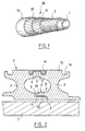
- Figure 1 is a schematic perspective view showing the successive layers of a pipe (here of the "smooth bore” type) to which the invention applies.
- Figure 2 is a partial view in longitudinal section of a first embodiment of a flexible pipe according to the invention, the vault metallic being formed of a metallic wire in I wound in helix stapled by the top.
- Figure 3 is a partial view in longitudinal section of a second embodiment of a metal vault according to the invention.
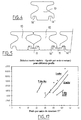
- Figures 4 to 16 show in schematic partial section five I-profile variants for form wire according to the invention combined if necessary, various stapling modes.
- Figure 17 is a graph illustrating for different types of wires form the relationship between the inertia * module and the weight per meter of pipe.
- a pipe "smooth bore” type includes a sheath from inside to outside internal polymeric seal 1, a metal vault 2 formed by the winding in a short pitch helix of at least one shaped metal wire, armor 30 resistant to axial traction in the longitudinal direction of the pipe and usually made up of one or more pairs of layers crossed 31, 32 of long-pitch winding in the opposite direction, and of a sheath polymeric external sealing 33.
- a hoop layer consisting of a short pitch winding of rectangular wire interposed between the pressure vault 2 and the first armor ply 31, and intermediate sheaths arranged between various armor layers.
- Figure 2 shows in longitudinal section an example of a vault pressure 2 according to the invention formed by a wire of form 10 of large section and therefore of great inertia, but lightened because made up of a profiled wire standing I section (or H lying) which has a web 3 and wings 4, 5, 6 and 7, the core 3 being wound substantially radially on and around the inner sheath 1 in a short pitch propeller, the outer wings 4, 5 and the wings internal 6, 7 of the consecutive turns facing and forming together a substantially confined volume 8 passing helically the vault 2.
- a profiled wire standing I section or H lying
- the shape of the wings can be very diverse, as we will see by the continuation, from the moment the wings on the internal side 6, 7 or external side 4, 5 allow the stapling of the wire. This is done either by self-stapling thanks to a special profile given to the form wire, either by an attached stapling wire that we generally prefer to have on the outside of the vault (stapling says "from above”) both for reasons of ease of manufacturing and better resistance of the pipe, especially for its dynamic use (riser).
- the wire metal 10 in I of the pressure vault 2 of the flexible pipe is stapled by a staple 11 at the level of the external face of the vault;
- clip 11 consists of a flat U-shaped wire helically wound in recesses 14 on the external face of the arch 2, that is to say at the level of the outer wings 4 and 5 of the metallic wire 10, and it connects the turns metal wire 10 wound helically at these wings 4 and 5.
- the clip 11 is advantageously arranged slightly recessed relative to the envelope volume of the external face so as to prevent the armor layers are not on the clip 11, causing risks of fatigue induced in dynamic use.
- the helical winding of the metal wire 10 is made leaving internal helical junctions and external at the level of the internal and external faces of the vault respectively pressure, these seals opening onto the internal volume 8.
- an anti-creep device is advantageously provided by a cover element 12 produced in FIG. 2 by the covering of parts 20, 21 of the asymmetrical wings 6, 7 opposite the internal sheath 1. These parts 20, 21 overlap longitudinally so that they admit the formation of the longitudinal gap 9, but on the other hand does not leave practically no passage in the thickness direction of the wings, so as to block access between the sheath 1 and the confined volume 8.
- FIG. 3 shows in more detail a preferred embodiment of I-shaped wire stapled from above by means of a staple 11 similar to that of the embodiment of FIG. 2, and intended for applications dynamic.
- the anti-creep cover element 12 here consists of a flat wire, for example in teflon-coated metal, helically wound in the face interior of the vault 2, at the level of the inner wings 6 and 7, symmetrical, metallic wire 3, thanks to recessed portions 13 facing formed on the length of the wings 6 and 7 of the consecutive turns of the most metallic wire 3 internal to the pipe.
- These recessed parts 13 are substantially in shape correspondence with said cover element 12 so that this the latter 12 can easily be accommodated there at least partially.
- the profile 10 in I has at its base of recesses 14 'intended for stapling from below by means of a staple 11 in U similar to that described in the previous embodiment.
- This mode stapling from below is in principle reserved for use of the pipe in static.
- Figures 6 to 9 illustrate possible profiles for wire 10, adjustments corresponding to the chosen stapling method that have not been shown in some of these figures.
- FIG. 6 the width of the upper wings 4 and 5 of the profile symmetrical 10 has been reduced.
- This profile is advantageously stapled from the interior as shown in Figure 13 by U-shaped clips 11 arranged in 14 "recesses formed on the upper part of the lower wings 6, 7, and an element such as a seal can be arranged above the clip 11.
- Figure 7 shows a profile similar to a basic I, the wings of which upper 4, 5 have been modified to include self-stapling hooks 18.
- Figure 8 shows a profile 10 with asymmetrical wings 4, 5 and 6, 7 allowing self-stapling from the top or from the bottom, the latter solution being illustrated in FIG. 14 which show self-stapling hooks 18 formed in a complementary manner on the wings 6, 7.
- FIG. 9 shows a profile 10 in I with very high inertia thanks to the strong thickness of the wings 4 to 7, which end in a flange 19.
- the flange 19 can be used for stapling, unless a stapling mode such as that of FIGS. 15 or 16 (described later) is chosen.
- a stapling by the wings has been described above, ie on the high side either on the bottom side, where the wings of the U-shaped clips 11 are housed in recesses 14 arranged entirely in the wings of the I-profile. allows the clip 11 to be completely retracted but requires a sufficient thickness for the wings which receive the recesses 14.
- the recesses 14 for receiving the staples are closer to the median plane of profile 10, even to the point of forming a single central groove receiving the wings of two adjacent U-shaped clips 11, as shown in Figures 10 (stapling from above) or 11 (stapling from the bottom). In this case, the clips 11 are no longer retracted.
- U-shaped staples have been described so far, but it goes without saying that we can adopt other staple profiles, for example in zeta as shown in FIG. 12 which shows an 11 '"zeta clip whose edges are housed in recesses 14 "'provided on the lower faces respectively and upper wings 6 and 7 (bottom stapling).
- Figure 15 shows an alternative stapling straddle, do not requiring no recess to accommodate the wings of the staples; here the staples 11 'in wide U spans two profiles 10 in I, the upper clips being offset from the lower staples so that the combination of the two staple wires effectively keeps the wings between their profiles 10.
- the staple clips 11 ′ are similar to those of the previous figure, except that they are housed in gorges central units 14, alternately at the top and bottom, profiles 10 similar to those of Figures 10 and 11.
Landscapes
- Engineering & Computer Science (AREA)
- General Engineering & Computer Science (AREA)
- Mechanical Engineering (AREA)
- Rigid Pipes And Flexible Pipes (AREA)
- Laying Of Electric Cables Or Lines Outside (AREA)
- Manufacturing Of Electric Cables (AREA)
- Storage Of Web-Like Or Filamentary Materials (AREA)
- Windings For Motors And Generators (AREA)
Description
- une gaine d'étanchéité interne réalisée en matière plastique, généralement polymère, résistant plus ou moins à l'action chimique du fluide à transporter ;
- une voûte de pression résistant principalement à la pression développée par le fluide dans la gaine d'étanchéité et constituée par l'enroulement en hélice à pas court (c'est-à-dire avec un angle d'enroulement voisin de 90°) autour de la gaine interne, d'un ou plusieurs fils métalliques de forme agrafés (auto-agrafables ou non) ;
- au moins une nappe (et généralement au moins deux nappes croisées) d'armures de traction dont l'angle d'armage mesuré sur l'axe longitudinal de la conduite est inférieur à 55° ; et
- une gaine de protection et d'étanchéité externe en polymère.
Claims (9)
- Conduite tubulaire flexible comprenant au moins, de l'intérieur vers l'extérieur, une gaine d'étanchéité interne (1), une voûte de pression cylindrique (2) constituée par l'enroulement en hélice à pas court d'un fil métallique de forme (10) agrafé, au moins une nappe (30) d'armures de traction enroulées à pas long et une gaine (33) de protection et d'étanchéité externe; caractérisée en ce que le fil de forme constituant la voûte est un fil à section en I ayant une âme centrale (3) d'épaisseur 1 et des ailes internes (6, 7) et externes (4, 5) de largeur égale ou différente L, avec 0,2 < 1/L < 0,6.
- Conduite selon la revendication 1, caractérisée en ce que le rapport de la hauteur H à la largeur L du fil (10) est inférieur à 1, et de préférence à 0,8.
- Conduite selon l'une quelconque des revendications 1 ou 2, caractérisée en ce que le rapport de la hauteur H à la largeur L du fil (10) est supérieur à 0,5 et de préférence à 0,7.
- Conduite selon l'une quelconque des revendications 1 à 3, caractérisée en ce que le rapport des inerties Ixx/Iyy du fil (10) est inférieur à 1.
- Conduite selon l'une quelconque des revendications 1 à 4, caractérisée en ce que le fil (10) est agrafé par le haut.
- Conduite selon l'une quelconque des revendications précédentes, caractérisée en ce que les ailes supérieures et/ou inférieures (4, 5, 6, 7) du fil (10) présentent des évidements (14).
- Conduite selon la revendication 6, caractérisée en ce que les évidements (14, 14', 18) sont formés du côté des ailes formant la face externe ou la face interne de la voûte (2).
- Conduite selon la revendication 7, caractérisée en ce que les évidements (14, 14', 18) reçoivent au moins partiellement une agrafe (11).
- Conduite selon la revendication 7, caractérisée en ce que les évidements (14, 14', 18) reçoivent au moins partiellement deux agrafes (11).
Applications Claiming Priority (5)
| Application Number | Priority Date | Filing Date | Title |
|---|---|---|---|
| FR9810254A FR2782141B1 (fr) | 1998-08-10 | 1998-08-10 | Conduite flexible resistante a fluage limite de la gaine d'etancheite |
| FR9810254 | 1998-08-10 | ||
| FR9815221 | 1998-12-02 | ||
| FR9815221A FR2782142B1 (fr) | 1998-08-10 | 1998-12-02 | Conduite flexible a enroulement de fil de forme en i |
| PCT/FR1999/001892 WO2000009899A2 (fr) | 1998-08-10 | 1999-07-30 | Conduite flexible a enroulement de fil de forme en i |
Publications (2)
| Publication Number | Publication Date |
|---|---|
| EP1135623A2 EP1135623A2 (fr) | 2001-09-26 |
| EP1135623B1 true EP1135623B1 (fr) | 2004-04-14 |
Family
ID=26234491
Family Applications (1)
| Application Number | Title | Priority Date | Filing Date |
|---|---|---|---|
| EP99936652A Expired - Lifetime EP1135623B1 (fr) | 1998-08-10 | 1999-07-30 | Conduite flexible a enroulement de fil de forme en i |
Country Status (9)
| Country | Link |
|---|---|
| US (1) | US6253793B1 (fr) |
| EP (1) | EP1135623B1 (fr) |
| AT (1) | ATE264466T1 (fr) |
| AU (1) | AU748814B2 (fr) |
| BR (1) | BR9911374A (fr) |
| DE (1) | DE69916491D1 (fr) |
| DK (1) | DK1135623T3 (fr) |
| FR (1) | FR2782142B1 (fr) |
| WO (1) | WO2000009899A2 (fr) |
Families Citing this family (41)
| Publication number | Priority date | Publication date | Assignee | Title |
|---|---|---|---|---|
| US7065462B2 (en) * | 1998-07-24 | 2006-06-20 | Merilab, Inc. | Vehicle wheel alignment by rotating vision sensor |
| BR9916335A (pt) * | 1998-12-16 | 2001-09-11 | Nkt Flexibles Is | Tubo flexìvel blindado e uso do mesmo |
| DK200001707A (da) * | 2000-04-25 | 2000-11-15 | Nkt Flexibles Is | Armeret fleksibelt rør samt anvendelse af samme |
| US6691743B2 (en) | 2000-05-10 | 2004-02-17 | Coflexip | Flexible pipe with wire or strip winding for maintaining armours |
| EP1154184B2 (fr) | 2000-05-10 | 2015-03-25 | Technip France | Conduite fléxible à enroulement de fil ou de bande pour le maintien des armures |
| FR2811055B1 (fr) | 2000-06-30 | 2003-05-16 | Coflexip | Conduite flexible a armures en feuillard |
| US7518724B2 (en) * | 2000-07-11 | 2009-04-14 | Maven Technologies | Image acquisition, processing, and display |
| FR2817318B1 (fr) | 2000-11-24 | 2002-12-27 | Coflexip | Conduite tubulaire flexible |
| FR2824890B1 (fr) * | 2001-05-18 | 2004-04-16 | Coflexip | Conduite flexible a voute agrafee par le bas |
| US6815026B2 (en) | 2002-11-07 | 2004-11-09 | Perry Philp | Helically-wound duct |
| GB0414837D0 (en) * | 2004-07-02 | 2004-08-04 | Booth John P | Improvements in or relating to tubular bodies and methods of forming same |
| FR2875285B1 (fr) * | 2004-09-13 | 2006-11-03 | Technip France Sa | Canalisations flexibles a conduites multiples preservees de la corrosion |
| US7867783B2 (en) | 2007-02-22 | 2011-01-11 | Maven Technologies, Llc | Apparatus and method for performing ligand binding assays on microarrays in multiwell plates |
| EP2129485B1 (fr) * | 2007-03-23 | 2015-04-22 | National Oilwell Varco Denmark I/S | Procédé de soudage d'une bande d'acier inoxydable duplex pour la production d'une couche d'armature d'un tuyau souple |
| US7863037B1 (en) | 2007-04-04 | 2011-01-04 | Maven Technologies, Llc | Ligand binding assays on microarrays in closed multiwell plates |
| US20090041633A1 (en) * | 2007-05-14 | 2009-02-12 | Dultz Shane C | Apparatus and method for performing ligand binding assays on microarrays in multiwell plates |
| US7799558B1 (en) | 2007-05-22 | 2010-09-21 | Dultz Shane C | Ligand binding assays on microarrays in closed multiwell plates |
| GB0712586D0 (en) | 2007-06-28 | 2007-08-08 | Wellstream Int Ltd | Flexible pipe |
| GB0800155D0 (en) * | 2008-01-07 | 2008-02-13 | Wellstream Int Ltd | Flexible pipe having pressure armour layer |
| US8276620B2 (en) * | 2008-03-05 | 2012-10-02 | Vo Dang The | Flexible pipe for offshore and other applications |
| US8039270B2 (en) * | 2008-05-22 | 2011-10-18 | Maven Technologies, Llc | Apparatus and method for performing ligand binding assays on microarrays in multiwell plates |
| US7981664B1 (en) | 2008-05-22 | 2011-07-19 | Maven Technologies, Llc | Apparatus and method for performing ligand binding assays on microarrays in multiwell plates |
| GB0820671D0 (en) | 2008-11-12 | 2008-12-17 | Wellstream Int Ltd | Armour reinforcement |
| US9562633B2 (en) | 2009-10-28 | 2017-02-07 | National Oilwell Varco Denmark I/S | Flexible pipe and a method of producing a flexible pipe |
| BR112012014653B1 (pt) | 2009-12-15 | 2020-11-10 | National Oilwell Varco Denmark I/S | tubo flexível não ligado, e, método para aumentar a rigidez de uma ou mais seções de comprimento enrijecidas de um tubo flexível não ligado |
| BR112012015987B1 (pt) | 2009-12-28 | 2020-11-10 | National Oilwell Varco Denmark I/S | tubo flexível não ligado |
| US8355133B2 (en) * | 2009-12-30 | 2013-01-15 | Maven Technologies, Llc | Biological testing with sawtooth-shaped prisms |
| FR2956183B1 (fr) | 2010-02-09 | 2012-03-16 | Technip France | Conduite flexible sous-marine comprenant une couche comprenant une resine polymere comprenant des nanoparticules de titane modifiees en surface |
| WO2011141033A1 (fr) | 2010-05-12 | 2011-11-17 | Nkt Flexibles I/S | Tuyau flexible à structure non liée |
| CA2805315A1 (fr) | 2010-07-14 | 2012-01-19 | National Oilwell Varco Denmark I/S | Tuyau souple sans liaison |
| US9188254B2 (en) | 2011-01-20 | 2015-11-17 | National Oilwell Varco Denmark I/S | Unbonded flexible pipe |
| US9458956B2 (en) | 2011-01-20 | 2016-10-04 | National Oilwell Varco Denmark I/S | Flexible armored pipe |
| GB201122472D0 (en) | 2011-12-30 | 2012-02-08 | Wellstream Int Ltd | Flexible pipe body and method of producing same |
| EP2825802A4 (fr) | 2012-03-13 | 2015-12-02 | Nat Oilwell Varco Denmark Is | Élément de renforcement pour tuyau flexible non lié |
| AU2013231726B2 (en) | 2012-03-13 | 2017-04-27 | National Oilwell Varco Denmark I/S | An unbonded flexible pipe with an optical fiber containing layer |
| BR112014025219A2 (pt) | 2012-04-12 | 2017-07-11 | Nat Oilwell Varco Denmark Is | método para produzir um tubo flexível não unido, e, tubo flexível não unido |
| US9574690B2 (en) | 2012-06-26 | 2017-02-21 | Ge Oil & Gas Uk Limited | Sleeve member, end fitting assembly and method of assembly of flexible pipe |
| DK177627B1 (en) | 2012-09-03 | 2013-12-16 | Nat Oilwell Varco Denmark Is | An unbonded flexible pipe |
| CN103644399B (zh) * | 2013-09-25 | 2015-11-18 | 中国海洋石油总公司 | 一种复合软管梯形截面嵌合抗压铠装层 |
| GB201615346D0 (en) | 2016-09-09 | 2016-10-26 | Ge Oil & Gas Uk Ltd | Interlocked layer and method of manufacture |
| CN108119708B (zh) * | 2018-01-17 | 2023-12-08 | 哈尔滨工程大学 | 一种非粘结柔性立管工型截面互锁抗压铠装层 |
Family Cites Families (13)
| Publication number | Priority date | Publication date | Assignee | Title |
|---|---|---|---|---|
| GB1081339A (en) | 1965-04-28 | 1967-08-31 | Angus George Co Ltd | Improvements in flexible ducting |
| FR2210267A5 (en) | 1972-12-08 | 1974-07-05 | Inst Francais Du Petrole | Flexible tube with spiral reinforcements - has cavities between shaped sections of spirals filled with an elastomer |
| CA1005366A (fr) * | 1972-12-08 | 1977-02-15 | Institut Francais Du Petrole | Conduite flexible etanche |
| FR2229913A2 (en) | 1973-05-16 | 1974-12-13 | Inst Francais Du Petrole | Flexible tube with spiral reinforcements - has cavities between shaped sections of spirals filled with an elastomer |
| DE3409734A1 (de) | 1984-03-20 | 1985-09-26 | The Furukawa Electric Co., Ltd., Tokio/Tokyo | Biegsame rohrleitung fuer den transport fliessender medien |
| CH673981A5 (fr) * | 1987-08-25 | 1990-04-30 | Ametex Ag | |
| US5275209A (en) * | 1988-05-09 | 1994-01-04 | Institut Francais Du Petrole | Hose including an aluminum alloy |
| FR2645795A1 (fr) | 1989-04-18 | 1990-10-19 | Gregoire Ets | Presse munie d'un obturateur pour vis d'archimede |
| FR2654795B1 (fr) | 1989-11-21 | 1992-03-06 | Coflexip | Conduite tubulaire flexible. |
| FR2727738A1 (fr) | 1994-12-05 | 1996-06-07 | Coflexip | Conduite tubulaire flexible comportant une nappe d'armure agrafee |
| FR2744511B1 (fr) | 1996-02-02 | 1998-03-06 | Coflexip | Conduite flexible a fluage limite de la gaine d'etancheite interne dans des armures |
| US5730188A (en) * | 1996-10-11 | 1998-03-24 | Wellstream, Inc. | Flexible conduit |
| FR2756605B1 (fr) | 1996-12-04 | 1998-12-31 | Coflexip | Conduite flexible a tube interne metallique ondule etanche au gaz |
-
1998
- 1998-12-02 FR FR9815221A patent/FR2782142B1/fr not_active Expired - Lifetime
-
1999
- 1999-07-30 DE DE69916491T patent/DE69916491D1/de not_active Expired - Lifetime
- 1999-07-30 EP EP99936652A patent/EP1135623B1/fr not_active Expired - Lifetime
- 1999-07-30 BR BR9911374-0A patent/BR9911374A/pt not_active IP Right Cessation
- 1999-07-30 WO PCT/FR1999/001892 patent/WO2000009899A2/fr not_active Ceased
- 1999-07-30 US US09/719,618 patent/US6253793B1/en not_active Expired - Lifetime
- 1999-07-30 DK DK99936652T patent/DK1135623T3/da active
- 1999-07-30 AT AT99936652T patent/ATE264466T1/de not_active IP Right Cessation
- 1999-07-30 AU AU51676/99A patent/AU748814B2/en not_active Ceased
Also Published As
| Publication number | Publication date |
|---|---|
| WO2000009899A3 (fr) | 2001-07-05 |
| AU5167699A (en) | 2000-03-06 |
| AU748814B2 (en) | 2002-06-13 |
| ATE264466T1 (de) | 2004-04-15 |
| US6253793B1 (en) | 2001-07-03 |
| BR9911374A (pt) | 2001-03-13 |
| DE69916491D1 (de) | 2004-05-19 |
| FR2782142A1 (fr) | 2000-02-11 |
| DK1135623T3 (da) | 2004-08-09 |
| EP1135623A2 (fr) | 2001-09-26 |
| FR2782142B1 (fr) | 2000-09-08 |
| WO2000009899A2 (fr) | 2000-02-24 |
Similar Documents
| Publication | Publication Date | Title |
|---|---|---|
| EP1135623A2 (fr) | Conduite flexible a enroulement de fil de forme en i | |
| EP1104527B1 (fr) | Conduite flexible resistante a fluage limite de la gaine d'etancheite | |
| EP1395769B1 (fr) | Conduite flexible a voute de pression agrafee par le bas | |
| EP1119726B1 (fr) | Conduite flexible a frette de forte inertie | |
| EP1299669B1 (fr) | Conduite flexible a armures en feuillard | |
| EP1340013B1 (fr) | Conduite tubulaire flexible | |
| EP0877887B1 (fr) | Conduite flexible a tube interne metallique ondule etanche aux gaz | |
| FR2727738A1 (fr) | Conduite tubulaire flexible comportant une nappe d'armure agrafee | |
| WO2003036152A1 (fr) | Conduite tubulaire flexible pour le transport d'hydrocarbures a carcasse constituee d'un element allonge enroule agrafe par un feuillard | |
| CA2027568C (fr) | Tube flexible comportant au moins un element allonge de renfort ayant un profil en t | |
| EP0870144A1 (fr) | Utilisation d'une conduite flexible ensouillee | |
| EP1242765A1 (fr) | Conduite flexible sous-marine de grande longueur a structure evolutive | |
| FR2852658A1 (fr) | Conduite tubulaire flexible pour le transport d'un fluide | |
| FR3008763A1 (fr) | Ensemble pour la realisation d'un joint filete pour le forage et l'exploitation des puits d'hydrocarbures et joint filete resultant | |
| EP1154184B2 (fr) | Conduite fléxible à enroulement de fil ou de bande pour le maintien des armures | |
| EP3022477A1 (fr) | Embout de connexion d'une conduite flexible, et conduite flexible associée |
Legal Events
| Date | Code | Title | Description |
|---|---|---|---|
| PUAI | Public reference made under article 153(3) epc to a published international application that has entered the european phase |
Free format text: ORIGINAL CODE: 0009012 |
|
| AK | Designated contracting states |
Kind code of ref document: A2 Designated state(s): AT BE CH CY DE DK ES FI FR GB GR IE IT LI LU MC NL PT SE |
|
| 17P | Request for examination filed |
Effective date: 20010925 |
|
| RAP1 | Party data changed (applicant data changed or rights of an application transferred) |
Owner name: COFLEXIP |
|
| GRAP | Despatch of communication of intention to grant a patent |
Free format text: ORIGINAL CODE: EPIDOSNIGR1 |
|
| RAP1 | Party data changed (applicant data changed or rights of an application transferred) |
Owner name: TECHNIP FRANCE |
|
| GRAS | Grant fee paid |
Free format text: ORIGINAL CODE: EPIDOSNIGR3 |
|
| GRAA | (expected) grant |
Free format text: ORIGINAL CODE: 0009210 |
|
| AK | Designated contracting states |
Kind code of ref document: B1 Designated state(s): AT BE CH CY DE DK ES FI FR GB GR IE IT LI LU MC NL PT SE |
|
| PG25 | Lapsed in a contracting state [announced via postgrant information from national office to epo] |
Ref country code: NL Free format text: LAPSE BECAUSE OF FAILURE TO SUBMIT A TRANSLATION OF THE DESCRIPTION OR TO PAY THE FEE WITHIN THE PRESCRIBED TIME-LIMIT Effective date: 20040414 Ref country code: IT Free format text: LAPSE BECAUSE OF FAILURE TO SUBMIT A TRANSLATION OF THE DESCRIPTION OR TO PAY THE FEE WITHIN THE PRE;WARNING: LAPSES OF ITALIAN PATENTS WITH EFFECTIVE DATE BEFORE 2007 MAY HAVE OCCURRED AT ANY TIME BEFORE 2007. THE CORRECT EFFECTIVE DATE MAY BE DIFFERENT FROM THE ONE RECORDED.SCRIBED TIME-LIMIT Effective date: 20040414 Ref country code: IE Free format text: LAPSE BECAUSE OF FAILURE TO SUBMIT A TRANSLATION OF THE DESCRIPTION OR TO PAY THE FEE WITHIN THE PRESCRIBED TIME-LIMIT Effective date: 20040414 Ref country code: FI Free format text: LAPSE BECAUSE OF FAILURE TO SUBMIT A TRANSLATION OF THE DESCRIPTION OR TO PAY THE FEE WITHIN THE PRESCRIBED TIME-LIMIT Effective date: 20040414 Ref country code: CY Free format text: LAPSE BECAUSE OF FAILURE TO SUBMIT A TRANSLATION OF THE DESCRIPTION OR TO PAY THE FEE WITHIN THE PRESCRIBED TIME-LIMIT Effective date: 20040414 Ref country code: AT Free format text: LAPSE BECAUSE OF FAILURE TO SUBMIT A TRANSLATION OF THE DESCRIPTION OR TO PAY THE FEE WITHIN THE PRESCRIBED TIME-LIMIT Effective date: 20040414 |
|
| REG | Reference to a national code |
Ref country code: GB Ref legal event code: FG4D Free format text: NOT ENGLISH |
|
| XX | Miscellaneous (additional remarks) |
Free format text: DERZEIT SIND DIE WIPO-PUBLIKATIONSDATEN A3 NICHT VERFUEGBAR. |
|
| REG | Reference to a national code |
Ref country code: CH Ref legal event code: EP |
|
| REF | Corresponds to: |
Ref document number: 69916491 Country of ref document: DE Date of ref document: 20040519 Kind code of ref document: P |
|
| REG | Reference to a national code |
Ref country code: IE Ref legal event code: FG4D Free format text: FRENCH |
|
| PG25 | Lapsed in a contracting state [announced via postgrant information from national office to epo] |
Ref country code: SE Free format text: LAPSE BECAUSE OF FAILURE TO SUBMIT A TRANSLATION OF THE DESCRIPTION OR TO PAY THE FEE WITHIN THE PRESCRIBED TIME-LIMIT Effective date: 20040714 Ref country code: GR Free format text: LAPSE BECAUSE OF FAILURE TO SUBMIT A TRANSLATION OF THE DESCRIPTION OR TO PAY THE FEE WITHIN THE PRESCRIBED TIME-LIMIT Effective date: 20040714 |
|
| PG25 | Lapsed in a contracting state [announced via postgrant information from national office to epo] |
Ref country code: DE Free format text: LAPSE BECAUSE OF FAILURE TO SUBMIT A TRANSLATION OF THE DESCRIPTION OR TO PAY THE FEE WITHIN THE PRESCRIBED TIME-LIMIT Effective date: 20040715 |
|
| PG25 | Lapsed in a contracting state [announced via postgrant information from national office to epo] |
Ref country code: ES Free format text: LAPSE BECAUSE OF FAILURE TO SUBMIT A TRANSLATION OF THE DESCRIPTION OR TO PAY THE FEE WITHIN THE PRESCRIBED TIME-LIMIT Effective date: 20040725 |
|
| PG25 | Lapsed in a contracting state [announced via postgrant information from national office to epo] |
Ref country code: LU Free format text: LAPSE BECAUSE OF NON-PAYMENT OF DUE FEES Effective date: 20040730 |
|
| PG25 | Lapsed in a contracting state [announced via postgrant information from national office to epo] |
Ref country code: MC Free format text: LAPSE BECAUSE OF NON-PAYMENT OF DUE FEES Effective date: 20040731 Ref country code: LI Free format text: LAPSE BECAUSE OF NON-PAYMENT OF DUE FEES Effective date: 20040731 Ref country code: CH Free format text: LAPSE BECAUSE OF NON-PAYMENT OF DUE FEES Effective date: 20040731 Ref country code: BE Free format text: LAPSE BECAUSE OF NON-PAYMENT OF DUE FEES Effective date: 20040731 |
|
| REG | Reference to a national code |
Ref country code: DK Ref legal event code: T3 |
|
| GBT | Gb: translation of ep patent filed (gb section 77(6)(a)/1977) |
Effective date: 20040812 |
|
| NLV1 | Nl: lapsed or annulled due to failure to fulfill the requirements of art. 29p and 29m of the patents act | ||
| REG | Reference to a national code |
Ref country code: IE Ref legal event code: FD4D |
|
| BERE | Be: lapsed |
Owner name: *TECHNIP FRANCE Effective date: 20040731 |
|
| PLBE | No opposition filed within time limit |
Free format text: ORIGINAL CODE: 0009261 |
|
| STAA | Information on the status of an ep patent application or granted ep patent |
Free format text: STATUS: NO OPPOSITION FILED WITHIN TIME LIMIT |
|
| REG | Reference to a national code |
Ref country code: CH Ref legal event code: PL |
|
| 26N | No opposition filed |
Effective date: 20050117 |
|
| BERE | Be: lapsed |
Owner name: *TECHNIP FRANCE Effective date: 20040731 |
|
| PG25 | Lapsed in a contracting state [announced via postgrant information from national office to epo] |
Ref country code: PT Free format text: LAPSE BECAUSE OF NON-PAYMENT OF DUE FEES Effective date: 20040914 |
|
| REG | Reference to a national code |
Ref country code: FR Ref legal event code: PLFP Year of fee payment: 18 |
|
| REG | Reference to a national code |
Ref country code: FR Ref legal event code: PLFP Year of fee payment: 19 |
|
| REG | Reference to a national code |
Ref country code: FR Ref legal event code: PLFP Year of fee payment: 20 |
|
| PGFP | Annual fee paid to national office [announced via postgrant information from national office to epo] |
Ref country code: FR Payment date: 20180705 Year of fee payment: 20 |
|
| PGFP | Annual fee paid to national office [announced via postgrant information from national office to epo] |
Ref country code: GB Payment date: 20180718 Year of fee payment: 20 Ref country code: DK Payment date: 20180625 Year of fee payment: 20 |
|
| REG | Reference to a national code |
Ref country code: DK Ref legal event code: EUP Effective date: 20190730 |
|
| REG | Reference to a national code |
Ref country code: GB Ref legal event code: PE20 Expiry date: 20190729 |
|
| PG25 | Lapsed in a contracting state [announced via postgrant information from national office to epo] |
Ref country code: GB Free format text: LAPSE BECAUSE OF EXPIRATION OF PROTECTION Effective date: 20190729 |