EP1136143A2 - Dispositif de changement de cylindres pour cages de laminoir, en particulier cages de laminoir à six cylindres - Google Patents
Dispositif de changement de cylindres pour cages de laminoir, en particulier cages de laminoir à six cylindres Download PDFInfo
- Publication number
- EP1136143A2 EP1136143A2 EP01105232A EP01105232A EP1136143A2 EP 1136143 A2 EP1136143 A2 EP 1136143A2 EP 01105232 A EP01105232 A EP 01105232A EP 01105232 A EP01105232 A EP 01105232A EP 1136143 A2 EP1136143 A2 EP 1136143A2
- Authority
- EP
- European Patent Office
- Prior art keywords
- roll
- cassette
- rolls
- roller
- chocks
- Prior art date
- Legal status (The legal status is an assumption and is not a legal conclusion. Google has not performed a legal analysis and makes no representation as to the accuracy of the status listed.)
- Granted
Links
Images




Classifications
-
- B—PERFORMING OPERATIONS; TRANSPORTING
- B21—MECHANICAL METAL-WORKING WITHOUT ESSENTIALLY REMOVING MATERIAL; PUNCHING METAL
- B21B—ROLLING OF METAL
- B21B31/00—Rolling stand structures; Mounting, adjusting, or interchanging rolls, roll mountings, or stand frames
- B21B31/08—Interchanging rolls, roll mountings, or stand frames, e.g. using C-hooks; Replacing roll chocks on roll shafts
- B21B31/10—Interchanging rolls, roll mountings, or stand frames, e.g. using C-hooks; Replacing roll chocks on roll shafts by horizontally displacing, i.e. horizontal roll changing
- B21B31/103—Manipulators or carriages therefor
-
- B—PERFORMING OPERATIONS; TRANSPORTING
- B21—MECHANICAL METAL-WORKING WITHOUT ESSENTIALLY REMOVING MATERIAL; PUNCHING METAL
- B21B—ROLLING OF METAL
- B21B13/00—Metal-rolling stands, i.e. an assembly composed of a stand frame, rolls, and accessories
- B21B13/02—Metal-rolling stands, i.e. an assembly composed of a stand frame, rolls, and accessories with axes of rolls arranged horizontally
- B21B2013/028—Sixto, six-high stands
-
- B—PERFORMING OPERATIONS; TRANSPORTING
- B21—MECHANICAL METAL-WORKING WITHOUT ESSENTIALLY REMOVING MATERIAL; PUNCHING METAL
- B21B—ROLLING OF METAL
- B21B2203/00—Auxiliary arrangements, devices or methods in combination with rolling mills or rolling methods
- B21B2203/30—Quick or bayonet couplings
-
- B—PERFORMING OPERATIONS; TRANSPORTING
- B21—MECHANICAL METAL-WORKING WITHOUT ESSENTIALLY REMOVING MATERIAL; PUNCHING METAL
- B21B—ROLLING OF METAL
- B21B31/00—Rolling stand structures; Mounting, adjusting, or interchanging rolls, roll mountings, or stand frames
- B21B31/08—Interchanging rolls, roll mountings, or stand frames, e.g. using C-hooks; Replacing roll chocks on roll shafts
- B21B31/12—Interchanging rolls, roll mountings, or stand frames, e.g. using C-hooks; Replacing roll chocks on roll shafts by vertically displacing
Definitions
- the invention relates to a roll changing device for Roll stands, in particular sextowalt stands, with one Roller change car with a change cassette
- Running rails for the chocks of the lower work roll and the two intermediate rolls of the Roll set of a sexto roll stand is equipped, the arranged in pairs on top of each other in horizontal planes Rails of the exchangeable cassette when changing the rollers appropriate tracks for the lower work roll and the Intermediate rolls and their chocks in the roll stand correspond and the roller changing carriage with drives for Moving the interchangeable cassette parallel to the roll stand and transverse to the rolling direction and with a device for Pull the work rolls and intermediate rolls out of the Roll stand in the interchangeable cassette and for inserting the rolls from the interchangeable cassette into the rolling stand.
- the roller changing carriage one from DE 197 47 013 A1 known roller changing device of this type is with four Pliers manipulators for pulling out the two work rolls and the two intermediate rolls from a sexto roll stand into the Exchangeable cassette and for inserting the rollers from the Exchangeable cassette in the roll stand.
- the upper intermediate roller and the two can be reground Work rolls that together with the roll chocks a sex roll stand was transferred to the removable cassette, removed from the removable cassette with a crane become. Due to the large dimensions of the two chocks the lower intermediate roller extends the space between the Running rails built into the frame of the removable cassette to move the two work rolls and the upper one Intermediate roller not out to remove the lower intermediate roller from the To be able to lift the exchangeable cassette out with a crane.
- the lower intermediate roller is also available to enable the replacement cassette the two chocks in a separate intermediate frame Interchangeable cassette stored to release the lower one Intermediate roller by a motor drive on the undercarriage the roll changing device parallel to the rolling direction of the the intermediate frame locked with the undercarriage is moved away, to then use the two chocks with a crane from the intermediate frame to highlight.
- the roll changing device according to the invention stands out through the following advantages:
- the trolley for pulling out the work rolls and of the intermediate rolls from a sexto roll stand into the Exchangeable cassette and for inserting the rollers from the Interchangeable cassette in the roll stand is with a rotatable Coupling button equipped, which optionally the coupling of the Work rolls and / or the intermediate rolls on the transport car enables.
- Equipping the exchangeable cassette with running rails for the work rolls and the upper intermediate roll including the roll chocks that come from the shifting area of the rolls can be swung out, allows for roller processing, e.g. for smoothing, lifting the two work rolls and of the two support rollers with a crane upwards from the Interchangeable cassette and lifting the smoothed or new rollers with the crane in the change cassette.
- the roller changing carriage can be operated individually or by Coupling two cars together in tandem when changing the rollers be used.
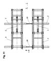
- roller changing device shown in Fig. 1 for Roll stands consist of two coupled roller changing car 1.1.
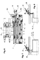
- Each roller change carriage 1 has one on the floor Rails on the roll stand can be moved parallel to the rolling direction a Base frame 2 with drive and one on the base frame 2 in Arrow direction b, c traversable transversely to rolling direction a a lifting cylinder 3 driven undercarriage 4 (FIGS. 6 and 11), on which a removable removable cassette 5 is placed.
- the exchangeable cassette 5 is provided with rails 6,6; 7.7; 8.8 for the chocks 10 - 12 of the lower ones provided with impellers 9 Work roll 13 and the upper and lower intermediate roll 15, 16 of the roller set of a sexto roll stand.
- Rails 6.6; 7.7; 8.8 of the exchangeable cassette 5 correspond when changing the roller with appropriate tracks for the Work rolls and intermediate rolls and their chocks in Mill stand.
- Each roller changing carriage 1 is motorized driven, on the rails 6.6 for the two Work rolls 13, 14 and their chocks 10, 17 between two End positions can be moved by the exchangeable cassette 5 Transport carriage 18 for pulling out the two work rolls 13, 14 and the two intermediate rollers 15, 16 together with their Chocks 10 - 12, 17 from a sexto roll stand into the Exchangeable cassette 5 and for inserting the rollers 13-16 with whose chocks 10 - 12, 17 from the removable cassette 5 in the Roll stand equipped (Figs. 2 and 6).
- Coupling 20 for optionally coupling the work rolls 13, 14 and / or the intermediate rollers 15, 16 when changing the rollers appropriate.
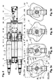
- the clutch 20 of the transport carriage 18 has one rotatable coupling head 21 with cams 23a, 23b, 24a, 24b, 29, 30, optionally by turning the coupling head 21 corresponding drivers 26, 27; 32, 33 on the chocks 11, 12 of the intermediate rolls 15, 16 and / or the chocks 10, 17 of the work rolls 13, 14 on the roll drive opposite side of the roll stand can be brought into engagement are.
- the coupling head 21 has two on an outer Turning circle 22 arranged to a certain angle of rotation ⁇ against each other twisted pairs of cams 23, 24, which by two diametrically opposed, spaced on the Rotation axis 25-25 of the coupling head 21 arranged cams 23a, 23a; 23b, 23b; 24a, 24a; 24b, 24b are formed and with diametrically opposite drivers 26, 27 to the Chocks 11, 12 of the intermediate rollers 15, 16 cooperate.
- the coupling head 21 is on an inner with two others Turning circle 28 diametrically opposed cam 29, 30 provided with a distance 31 to the pairs of cams 23, 24th on the outer turning circle 22 on the axis of rotation 25-25 of the Coupling head 21 are arranged and diametrically oppositely arranged drivers 32, 33 on the Chocks 10, 17 of the work rolls 13, 14 cooperate.
- the different coupling positions of the coupling head 21 of the trolley 18 are by the Figs. 3a - 3d illustrates, Fig. 3a, the coupling position for coupling the Work rolls 13, 14 and the intermediate rolls 15, 16, Fig. 3b a Intermediate position, Fig. 3c, the coupling position for coupling the Work rolls 13, 14 and Fig. 3d the coupling position of the Coupling head 21 for coupling the intermediate rollers 15, 16 shows.
- the in the change cassette 5 of a roller change carriage 1 built-in two tracks 6, 6 for the lower work roll 13 and their two chocks 10 and the two Running rails 7, 7 for the upper intermediate roller 15 and their Chocks 11 are by manual swivel drives 37, which consists of a lever linkage 38, a gear 39 and a Hand crank 40 consist of the displacement range of the Work rolls 13, 14 and the intermediate rolls 15, 16 for the Removing the rolls to be smoothed from the exchangeable cassette 5 and the introduction of the ground rolls in the Exchangeable cassette can be swiveled up and away by means of a crane for the roll change in the roll stand back into yours Horizontal position can be swiveled back (FIGS. 4 and 5).
- Two roller changing carriages 1, 1 are attached to the base frame 2 attached couplings 44 to a tandem car with each other detachable ( Figures 1 and 11).
- the roll change can faster than with a simple roller change carriage be carried out, because a before the roll change Interchangeable cassette of the tandem car with smoothed or new ones Rollers can be loaded.
Landscapes
- Engineering & Computer Science (AREA)
- Mechanical Engineering (AREA)
- Bending Of Plates, Rods, And Pipes (AREA)
- Metal Rolling (AREA)
Applications Claiming Priority (2)
| Application Number | Priority Date | Filing Date | Title |
|---|---|---|---|
| DE20004856U DE20004856U1 (de) | 2000-03-16 | 2000-03-16 | Walzenwechselvorrichtung für Walzgerüste, insbesondere Sextowalzgerüste |
| DE20004856U | 2000-03-16 |
Publications (3)
| Publication Number | Publication Date |
|---|---|
| EP1136143A2 true EP1136143A2 (fr) | 2001-09-26 |
| EP1136143A3 EP1136143A3 (fr) | 2004-01-28 |
| EP1136143B1 EP1136143B1 (fr) | 2005-06-01 |
Family
ID=7938842
Family Applications (1)
| Application Number | Title | Priority Date | Filing Date |
|---|---|---|---|
| EP01105232A Expired - Lifetime EP1136143B1 (fr) | 2000-03-16 | 2001-03-03 | Dispositif de changement de cylindres pour cages de laminoir, en particulier cages de laminoir à six cylindres |
Country Status (2)
| Country | Link |
|---|---|
| EP (1) | EP1136143B1 (fr) |
| DE (2) | DE20004856U1 (fr) |
Cited By (6)
| Publication number | Priority date | Publication date | Assignee | Title |
|---|---|---|---|---|
| WO2003099479A1 (fr) * | 2002-05-24 | 2003-12-04 | Sms Demag Aktiengesellschaft | Procede et dispositif pour changer des paires de cylindres de travail ou des paires de cylindres d'appui dans des cages de laminoir |
| WO2007080087A1 (fr) * | 2006-01-09 | 2007-07-19 | Sms Demag Ag | Procede et dispositif de remplacement de cylindres |
| CN101374612B (zh) * | 2006-01-09 | 2011-04-20 | Sms西马格股份公司 | 支撑结构和用于搬运/输送工作辊的方法 |
| EP1806186B2 (fr) † | 2006-01-04 | 2015-08-26 | Siemens VAI Metals Technologies SAS | Installation de laminage |
| CN105344714A (zh) * | 2015-12-19 | 2016-02-24 | 重庆麦拓科技有限公司 | 一种轧机快速换辊装置 |
| WO2022165920A1 (fr) * | 2021-02-08 | 2022-08-11 | 太原科技大学 | Laminoir à coin croisé intelligent pour essieu de grande dimension dans le trafic ferroviaire |
Families Citing this family (5)
| Publication number | Priority date | Publication date | Assignee | Title |
|---|---|---|---|---|
| IT1397382B1 (it) * | 2010-01-08 | 2013-01-10 | Studio Crespi S R L | Gabbia reversibile con smontaggio in linea dei cilindri. |
| ITTO20120001A1 (it) * | 2012-01-04 | 2013-07-05 | Mino S P A | Laminatoio multicilindro, in particolare di tipo sesto |
| CN105312871A (zh) * | 2014-10-21 | 2016-02-10 | 江苏亚威机床股份有限公司 | 一种快速换辊小车 |
| CN109848220A (zh) * | 2018-12-27 | 2019-06-07 | 二重(德阳)重型装备有限公司 | 四辊轧机的轧辊更换方法 |
| DE102021207948A1 (de) | 2021-07-23 | 2023-01-26 | Sms Group Gmbh | Walzenwechselvorrichtung zum Wechseln der Arbeits- und/oder Zwischenwalzen eines Walzgerüsts |
Family Cites Families (5)
| Publication number | Priority date | Publication date | Assignee | Title |
|---|---|---|---|---|
| DE3244200A1 (de) * | 1982-11-30 | 1984-05-30 | SMS Schloemann-Siemag AG, 4000 Düsseldorf | Walzenwechselvorrichtung fuer sechswalzen-walzgerueste |
| JPS59183912A (ja) * | 1983-04-04 | 1984-10-19 | Nippon Steel Corp | 6段圧延機のロール組替装置 |
| JP2812423B2 (ja) * | 1994-04-07 | 1998-10-22 | 住友金属工業株式会社 | 6段圧延機のロール組替装置 |
| FR2769525B1 (fr) * | 1997-10-10 | 1999-12-31 | Kvaerner Metals Clecim | Dispositif de changement des cylindres de travail et/ou des cylindres intermediaires d'une cage de laminoir, et ratelier de stockage pour un tel dispositif |
| DE19747013A1 (de) * | 1997-10-24 | 1999-04-29 | Schloemann Siemag Ag | Vorrichtung und Verfahren für schnellen Walzenwechsel an einem Sechswalzen-Walzgerüst |
-
2000
- 2000-03-16 DE DE20004856U patent/DE20004856U1/de not_active Expired - Lifetime
-
2001
- 2001-03-03 EP EP01105232A patent/EP1136143B1/fr not_active Expired - Lifetime
- 2001-03-03 DE DE50106359T patent/DE50106359D1/de not_active Expired - Lifetime
Cited By (9)
| Publication number | Priority date | Publication date | Assignee | Title |
|---|---|---|---|---|
| WO2003099479A1 (fr) * | 2002-05-24 | 2003-12-04 | Sms Demag Aktiengesellschaft | Procede et dispositif pour changer des paires de cylindres de travail ou des paires de cylindres d'appui dans des cages de laminoir |
| US7165432B2 (en) | 2002-05-24 | 2007-01-23 | Sms Demag Ag | Method and device for changing pairs of working rolls and/or pairs of back-up rolls on roll stands |
| CN100341636C (zh) * | 2002-05-24 | 2007-10-10 | Sms迪马格股份公司 | 用于更换轧机机座上工作辊对和/或支承辊对的方法和装置 |
| EP1806186B2 (fr) † | 2006-01-04 | 2015-08-26 | Siemens VAI Metals Technologies SAS | Installation de laminage |
| WO2007080087A1 (fr) * | 2006-01-09 | 2007-07-19 | Sms Demag Ag | Procede et dispositif de remplacement de cylindres |
| CN101374612B (zh) * | 2006-01-09 | 2011-04-20 | Sms西马格股份公司 | 支撑结构和用于搬运/输送工作辊的方法 |
| CN105344714A (zh) * | 2015-12-19 | 2016-02-24 | 重庆麦拓科技有限公司 | 一种轧机快速换辊装置 |
| CN105344714B (zh) * | 2015-12-19 | 2017-09-01 | 重庆麦拓科技有限公司 | 一种轧机快速换辊装置 |
| WO2022165920A1 (fr) * | 2021-02-08 | 2022-08-11 | 太原科技大学 | Laminoir à coin croisé intelligent pour essieu de grande dimension dans le trafic ferroviaire |
Also Published As
| Publication number | Publication date |
|---|---|
| DE20004856U1 (de) | 2000-05-25 |
| EP1136143A3 (fr) | 2004-01-28 |
| EP1136143B1 (fr) | 2005-06-01 |
| DE50106359D1 (de) | 2005-07-07 |
Similar Documents
| Publication | Publication Date | Title |
|---|---|---|
| EP1954416B1 (fr) | Procede et dispositif de manipulation/transport de cylindres de travail et/ou de cylindres d'appui | |
| WO2008046728A1 (fr) | Chariot de transport relié au sol, en particulier pour le transport de conteneurs | |
| AT396584B (de) | Hebeeinrichtung zum anheben von fahrzeugen | |
| DE2451165A1 (de) | Transportfahrzeug zur befoerderung von containern | |
| WO1996008623A1 (fr) | Installation de reception, de stockage intermediaire et de sortie d'objets mobiles | |
| EP1136143B1 (fr) | Dispositif de changement de cylindres pour cages de laminoir, en particulier cages de laminoir à six cylindres | |
| WO2010013082A1 (fr) | Palette avec mécanisme de roulement mobile | |
| DE102010000246B4 (de) | Anordnung und Verfahren zum Transportieren einer schweren Last | |
| DE102018210889A1 (de) | Verfahren und Vorrichtung zum Wechseln von Stützwalzen an einem Walzgerüst | |
| DE2228196C3 (de) | Einrichtung zum Auswechseln von Gleisjochen | |
| DE4240125C2 (de) | Hydraulische Absetzeinrichtung für Wechselaufbauten | |
| EP2447191B1 (fr) | Dispositif de transport pour conteneurs | |
| DE537726C (de) | Rollgestell fuer Kraftfahrzeuge | |
| EP3473580A1 (fr) | Dispositif d'embarquement | |
| DE69511673T2 (de) | Auf Eisenbahnwagen transportierbare Rampen zum Verladen von Standard-Sattelaufliegern auf, aus besonderen Einheiten zusammengestellte, Züge | |
| DE102019119709B4 (de) | Transportwagen | |
| DE102009032905B4 (de) | Stützbock für einen Taschenwagen | |
| DE957449C (de) | Dreiachsiges Kraftfahrzeug zur Befoerderung von Eisenbahnwagen auf gewoehnlichen Strassen | |
| DE69002919T2 (de) | Stütze für anhänger. | |
| DE2518778C2 (de) | Querverschiebeeinrichtung für die Ladebrücke von Eisenbahntiefladewagen | |
| DE19733963C2 (de) | Verfahren und Vorrichtung zum Umschlagen von Ladung | |
| DE29603699U1 (de) | Auffahrhebebühne | |
| DE202019100918U1 (de) | Vorrichtung zum Radwechsel | |
| DE202025100619U1 (de) | Rollenbahneinheit zum rollengelagerten Verschieben eines Sarges sowie Bestattungsfahrzeug und Fahrgestell | |
| WO2011134771A1 (fr) | Dispositif de manutention et/ou de transport, au moins par paires, de cylindres de soutien et/ou de cylindres de travail d'une cage de laminoir |
Legal Events
| Date | Code | Title | Description |
|---|---|---|---|
| PUAI | Public reference made under article 153(3) epc to a published international application that has entered the european phase |
Free format text: ORIGINAL CODE: 0009012 |
|
| AK | Designated contracting states |
Kind code of ref document: A2 Designated state(s): AT BE CH CY DE DK ES FI FR GB GR IE IT LI LU MC NL PT SE TR |
|
| AX | Request for extension of the european patent |
Free format text: AL;LT;LV;MK;RO;SI |
|
| PUAL | Search report despatched |
Free format text: ORIGINAL CODE: 0009013 |
|
| AK | Designated contracting states |
Kind code of ref document: A3 Designated state(s): AT BE CH CY DE DK ES FI FR GB GR IE IT LI LU MC NL PT SE TR |
|
| AX | Request for extension of the european patent |
Extension state: AL LT LV MK RO SI |
|
| 17P | Request for examination filed |
Effective date: 20040325 |
|
| AKX | Designation fees paid |
Designated state(s): DE FR GB IT |
|
| GRAP | Despatch of communication of intention to grant a patent |
Free format text: ORIGINAL CODE: EPIDOSNIGR1 |
|
| GRAS | Grant fee paid |
Free format text: ORIGINAL CODE: EPIDOSNIGR3 |
|
| GRAA | (expected) grant |
Free format text: ORIGINAL CODE: 0009210 |
|
| AK | Designated contracting states |
Kind code of ref document: B1 Designated state(s): DE FR GB IT |
|
| REG | Reference to a national code |
Ref country code: GB Ref legal event code: FG4D Free format text: NOT ENGLISH |
|
| GBT | Gb: translation of ep patent filed (gb section 77(6)(a)/1977) |
Effective date: 20050601 |
|
| REG | Reference to a national code |
Ref country code: IE Ref legal event code: FG4D Free format text: LANGUAGE OF EP DOCUMENT: GERMAN |
|
| REF | Corresponds to: |
Ref document number: 50106359 Country of ref document: DE Date of ref document: 20050707 Kind code of ref document: P |
|
| PLBE | No opposition filed within time limit |
Free format text: ORIGINAL CODE: 0009261 |
|
| STAA | Information on the status of an ep patent application or granted ep patent |
Free format text: STATUS: NO OPPOSITION FILED WITHIN TIME LIMIT |
|
| ET | Fr: translation filed | ||
| 26N | No opposition filed |
Effective date: 20060302 |
|
| REG | Reference to a national code |
Ref country code: FR Ref legal event code: PLFP Year of fee payment: 16 |
|
| PGFP | Annual fee paid to national office [announced via postgrant information from national office to epo] |
Ref country code: GB Payment date: 20160322 Year of fee payment: 16 Ref country code: FR Payment date: 20160322 Year of fee payment: 16 |
|
| PGFP | Annual fee paid to national office [announced via postgrant information from national office to epo] |
Ref country code: DE Payment date: 20160523 Year of fee payment: 16 |
|
| PGFP | Annual fee paid to national office [announced via postgrant information from national office to epo] |
Ref country code: IT Payment date: 20160318 Year of fee payment: 16 |
|
| REG | Reference to a national code |
Ref country code: DE Ref legal event code: R119 Ref document number: 50106359 Country of ref document: DE |
|
| GBPC | Gb: european patent ceased through non-payment of renewal fee |
Effective date: 20170303 |
|
| REG | Reference to a national code |
Ref country code: FR Ref legal event code: ST Effective date: 20171130 |
|
| PG25 | Lapsed in a contracting state [announced via postgrant information from national office to epo] |
Ref country code: DE Free format text: LAPSE BECAUSE OF NON-PAYMENT OF DUE FEES Effective date: 20171003 Ref country code: FR Free format text: LAPSE BECAUSE OF NON-PAYMENT OF DUE FEES Effective date: 20170331 |
|
| PG25 | Lapsed in a contracting state [announced via postgrant information from national office to epo] |
Ref country code: GB Free format text: LAPSE BECAUSE OF NON-PAYMENT OF DUE FEES Effective date: 20170303 Ref country code: IT Free format text: LAPSE BECAUSE OF NON-PAYMENT OF DUE FEES Effective date: 20170303 |