EP1136150A2 - Méthode de formage d' une projection intégrale dans une pièce par fluotournage et article produit par cette méthode - Google Patents
Méthode de formage d' une projection intégrale dans une pièce par fluotournage et article produit par cette méthode Download PDFInfo
- Publication number
- EP1136150A2 EP1136150A2 EP01106049A EP01106049A EP1136150A2 EP 1136150 A2 EP1136150 A2 EP 1136150A2 EP 01106049 A EP01106049 A EP 01106049A EP 01106049 A EP01106049 A EP 01106049A EP 1136150 A2 EP1136150 A2 EP 1136150A2
- Authority
- EP
- European Patent Office
- Prior art keywords
- work
- thickness
- forming
- axis
- forming roller
- Prior art date
- Legal status (The legal status is an assumption and is not a legal conclusion. Google has not performed a legal analysis and makes no representation as to the accuracy of the status listed.)
- Granted
Links
Images



Classifications
-
- B—PERFORMING OPERATIONS; TRANSPORTING
- B21—MECHANICAL METAL-WORKING WITHOUT ESSENTIALLY REMOVING MATERIAL; PUNCHING METAL
- B21D—WORKING OR PROCESSING OF SHEET METAL OR METAL TUBES, RODS OR PROFILES WITHOUT ESSENTIALLY REMOVING MATERIAL; PUNCHING METAL
- B21D22/00—Shaping without cutting, by stamping, spinning, or deep-drawing
- B21D22/14—Spinning
-
- Y—GENERAL TAGGING OF NEW TECHNOLOGICAL DEVELOPMENTS; GENERAL TAGGING OF CROSS-SECTIONAL TECHNOLOGIES SPANNING OVER SEVERAL SECTIONS OF THE IPC; TECHNICAL SUBJECTS COVERED BY FORMER USPC CROSS-REFERENCE ART COLLECTIONS [XRACs] AND DIGESTS
- Y10—TECHNICAL SUBJECTS COVERED BY FORMER USPC
- Y10T—TECHNICAL SUBJECTS COVERED BY FORMER US CLASSIFICATION
- Y10T82/00—Turning
- Y10T82/10—Process of turning
-
- Y—GENERAL TAGGING OF NEW TECHNOLOGICAL DEVELOPMENTS; GENERAL TAGGING OF CROSS-SECTIONAL TECHNOLOGIES SPANNING OVER SEVERAL SECTIONS OF THE IPC; TECHNICAL SUBJECTS COVERED BY FORMER USPC CROSS-REFERENCE ART COLLECTIONS [XRACs] AND DIGESTS
- Y10—TECHNICAL SUBJECTS COVERED BY FORMER USPC
- Y10T—TECHNICAL SUBJECTS COVERED BY FORMER US CLASSIFICATION
- Y10T83/00—Cutting
- Y10T83/04—Processes
Definitions
- the present invention relates in general to a spinning process which is one of plastic working processes and more specifically to a method of forming an integral tubular projection which is shaped like a boss, in a disk-shaped work by spinning.
- the prior art spinning process is adapted to form a boss of a part by collecting a material of a work around a pin gradually by shear spinning and pushing it into a space defined by an upper surface of a lower jig, a lower surface of an upper pressure jig and an outer circumferential surface of the pin integral with the lower die, namely, materially by the full closed die forging technique. Accordingly, the inner and outer diameters of the boss of the formed part are determined depending upon the diameter of the pin.
- a problem of the prior art spinning process is that unless the lower jig is replaced by one having a pin of a different size, a part having a boss of a different inner diameter cannot be produced. Another problem is that it is necessary that a work is previously formed with a hole into which the above described pin is to be inserted. The problems inevitably increase the number of necessary process steps and therefore the manufacturing cost.
- a method of forming an integral tubular projection in a disk-shaped work comprising: driving the work to rotate in such a manner that the flat plate portion is held positioned on a plane; spinning the work by using a forming roller whose axis is inclined to form a predetermined angle with an axis of rotation of the work, in such a manner as to cause a section of the work to decrease in thickness and another section of the work to increase in thickness and grow to the tubular projection;
- a method of forming an integral tubular projection in a disk-shaped work by spinning comprising: forming the work into a shallow dish shape, the shallow dish-shaped work having an inclined wall portion other than a flat central portion where the projection is to be formed; supporting the shallow dish-shaped work on a mandrel shaped correspondingly to the shallow dish-shaped work; rotating the shallow dish-shaped work about an axis thereof together with the mandrel; pushing a forming roller against the inclined wall portion of the work while moving the roller along the inclined wall portion of the work and thereby causing the inclined wall portion to partially decrease in thickness and the central portion to partially increase in thickness and grow to the tubular projection.
- a method of forming a disk-shaped part having an integral, concentric boss in the form of a hollow cylindrical projection, by spinning comprising: preparing a work in the form of a flat circular plate; holding the work between a mandrel and a tail stock and driving the work to rotate; pushing a forming roller against the work and thereby causing a radially outer section of the work to decrease in thickness and a radially inner section of the work to increase in thickness and grow to the boss while holding an inner circumferential surface of the projection apart from an outer circumferential surface of the tail stock.
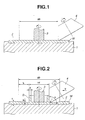
- Boss B is in the form of a tubular or hollow cylindrical projection
- work W is a blanked, flat circular steel plate.
- a mandrel is indicated by 1 and formed with recess 2 for receiving therein work W.
- Work W is disposed in recess 2 and fixedly held by tail stock 3 which pushes the central portion of work W against mandrel 1.
- Work W is driven to rotate about a center axis thereof together with mandrel 1 and tail stock 2, i.e., in a way as to be held positioned on a plane. Since in this embodiment work W is in the form of a simple, flat circular plate, work W serves in its entirety as a flat plate portion to be formed with boss B.
- Forming roller 4 used for shear spinning is solid and in the form of a truncated cone. Forming roller 4 is disposed so as to have an axis of rotation which is inclined to form a predetermined angle with the axis of work W. However, a conical forming surface of forming roller 4 is constructed and arranged so as to be nearly parallel to the axis of work W at a surface portion nearest to the same.
- Forming roller 4 is pushed against work W which is being driven to rotate and is moved at a constant speed toward the axis of work W to decrease the thickness of work W.
- forming roller 4 for shear spinning is not necessarily single but two or more of forming rollers 4 can be used so long as the points where rollers 4 are brought into contact with work W are located in the same circle about the axis of rotation of work W.
- the movement of forming roller 4 causes work W to partially decrease in thickness for thereby causing the material of work W to be collected partially and gradually at a central portion of work W to protrude axially and grow to boss B in the form of a tubular projection as shown in Fig. 2. Namely, the movement of forming roller 4 causes a section of work W to decrease in thickness and another section of work W, which is located nearer to the axis of rotation of same, to increase in thickness and grow to boss B.
- boss B having a smooth inner circumferential surface and constant in thickness can be formed though the inner circumferential side of the boss is not restrained by tail stock 3. Accordingly, boss B having a good concentricity of the inner and outer circumferential surfaces and an accurate, hollow cylindrical shape can be formed.
- t is a thickness of work W
- h is a depth by which forming roller 4 cuts into work W
- D is a diameter of a circle including a point where forming or spinning by forming roller 4 starts
- d is the outer diameter of boss B
- T is a thickness of a wall of boss B
- ⁇ is an angle which forming roller 4 forms with work W (i.e., the angle which the forming surface portion of forming roller 4 which is located nearest to the axis of work W, forms with a side surface of the work W when observed in a section taken along a plane including the axis of rotation of work W and an axis of forming roller 4)
- V is a volume of boss B
- thickness T of boss B, depth h, working speed v and radius r of curvature of the tip end of forming roller 4 have the following correlation, and thickness T of boss B can be set optionally.
- Figs. 3 to 5 illustrate how a defect in forming occurs when either of the above described working conditions deviates from a required range.
- a defect is caused as shown in Fig. 3, i.e., the rear surface of work W is partially elevated at a corresponding position to the root of boss B to cause portion Q1 which is excessively decreased in thickness, or a defect is caused as shown in Fig. 4, i.e., there occurs a break in a flat portion of work W, which has been decreased in thickness. It is considered that these defects are caused for the reason that the thickness of work W was decreased excessively to such an extent as to cause plastic flow of work W itself to reach to the limit.
- Fig. 6 shows a second embodiment of the present invention.
- work W1 is previously formed with prepared hole H at the central portion thereof.
- Tail stock 3 is formed with reduced diameter portion 5 which extends through prepared hole H.
- Mandrel 1 is formed with positioning hole 6 for receiving reduced diameter portion 5.
- work W1 is positioned by two kinds of engagement, i.e., engagement of the outer cylindrical surface of work W1 in recess 2 and engagement of prepared hole H with reduced diameter portion 5 of tail stock 3.
- Fig. 7 shows a third embodiment. This embodiment is substantially similar to the first embodiment except that work W2 is previously formed with axially flanged outer peripheral end portion F and boss B is formed at flat portion R other than flanged outer peripheral end portion F.
- the second and third embodiments can produce substantially the same effect as the first embodiment.
- Figs. 8 and 9 show a fourth embodiment.
- This embodiment is substantially similar to the previous embodiments except that work W3 is previously formed into a shallow dish shape so that a portion of work W3 other than the flat central portion at which boss B is to be formed, is formed into inclined wall portion S which inclines at predetermined angle ⁇ .
- work W3 is formed at the flat central portion thereof with prepared hole H by press forming or the like and at the same time the portion of work W3 other than the central portion at which boss B in the form of a projection is to be formed, is previously processed by press forming or spinning so as to incline or taper at predetermined angle ⁇ and be thereby formed into inclined or tapered wall portion S such that work W1 is generally formed into a shallow dish shape.
- mandrel 11 for supporting work W1 is formed with support surface 11a corresponding in shape to inclined wall portion S and positioning hole 12 at the central part thereof.
- Tail stock 13 for pushing work W3 against mandrel 11 and thereby holding it fixedly is formed with reduced diameter portion 14 that fits in prepared hole H.
- Work W3 is disposed so as to cover mandrel 11, i.e., so as to bring inclined wall portion S into contact with support surface 11a. Under this condition, the peripheral portion of work W3 is clamped by chuck 15 and at the same time tail stock 13 with reduced diameter portion 14 fitted in prepared hole H is pushed with a predetermined pressure for thereby fixedly holding the central portion of work W3 while positioning the same by the effect of engagement of reduced diameter portion 14 with prepared hole H.
- Forming roller 4 used in this embodiment is solid and truncated cone-shaped similarly to those of the previous embodiments.
- Forming roller 4 has an axis of rotation which is inclined to form a predetermined angle with the axis of work W3.
- Forming roller 4 is constructed and arranged so as to have, when observed in section taken along a plane including the axis of rotation of tail stock 13 and the axis of rotation of forming roller 4, a surface portion 4a which is nearest to the axis of rotation of tail stock 13 and which is always held nearly parallel with the axis of rotation of work W3.
- forming roller 4 is pushed against inclined wall portion S of work W3 and moved along inclination ⁇ of work W3 toward the center of same, i.e., from a lower side of inclined wall portion S to a higher side at predetermined speed v in order to decrease the thickness of work W3.
- forming roller 4 for spinning is not necessarily single but two or more of rollers 4 can be used so long as contact portions of rollers 4 in contact with work W3 are located on the same circle around the axis of rotation of work W3.
- radius r of curvature of the tip end of forming roller 4 and speed v of movement of forming roller 4 are basically the same as that of the first embodiment.
- movement of forming roller 4 causes work W3 to partially decrease in thickness to allow the material of work W3 to be collected gradually at the central portion of work W3, thus causing the central portion of work W3 to protrude and grow to boss B in the form of a hollow, cylindrical projection.
- movement of forming roller 4 causes a section of inclined wall portion S of work W3 to decrease in thickness and a section of work W3 at or adjacent the flat central portion thereof to increase in thickness to protrude and grow to boss B.
- boss B is not restrained at the inner circumferential surface side thereof by tail stock 13, it can have a smooth cylindrical surface while being uniform in thickness T similarly to the previous embodiment, thus making it possible to obtain boss B which has an accurate concentricity of the inner and outer circumferential surfaces and an accurate hollow cylindrical shape.
- Fig. 10 shows the result of examination. From this examination, it was understood that even if depth h by which forming roller 4 cut into work W3 was constantly 1.2 mm thickness T1 of formed boss B increased with increase of inclination ⁇ of inclined wall S. In the meantime, in the graph of Fig. 10, inclination of 0 degree corresponds to the forming processes of the first and second embodiments.
- inclination ⁇ ranges from 5 to 40 degrees and it is most preferable that inclination ⁇ ranges from 15 to 35 degrees. It was found that even if depth h in this embodiment, by which forming roller 4 cut into work W1 was substantially equal to that in the first and second embodiments, thickness T1 of boss B could be 1.1 to 1.3 times larger as compared with that in the first and second embodiments.
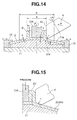
- Fig. 14 shows a fifth embodiment of the present invention.
- This embodiment differs from the fourth embodiment in that tail stock 14 is not adapted to penetrate through work W4 but simply pushes work W4 against mandrel 11 to hold it fixedly. Except for the above, this embodiment is substantially similar to the fourth embodiment and can produce substantially the same effect.
- boss B2 having a desired shape can be formed even if there does not exist at least any portion of mandrel 11 in the space inside boss B2 (i.e., cross hatched portion C).
- Fig. 17 shows an example of product P which can be formed by repeating the above described spinning processes for causing a section of a work to increase in thickness for several times.
- This kind of product P of a complicated shape can be formed from a single disk-shaped work, provided that the above described working conditions are satisfied.
- indicated by G in the figure is an internal gear which may be a splined or serrated gear.
- the internal gear is formed by first carrying out the above described spinning process for increase in thickness and thereafter a shear spinning process.
- the portions indicated by X and Y are formed by first carrying out the above described spinning process for increase in thickness and then shear spinning for forming the outer circumferential shape and further by carrying out shear spinning for finishing the inner circumferential shape.
- the finishing for the inner circumferential shape can be made by machining in place of shear spinning.
- the work is not limited to those described above but can have various shapes, provided that it has a flat portion at which a projection is to be formed.
- the projection to be formed by spinning is not limited to a hollow cylindrical shape but can be various shapes such as a conical shape.
- the projection is not always required to be positioned concentrically but can be formed eccentrically by driving the work about an eccentric axis.
Landscapes
- Engineering & Computer Science (AREA)
- Mechanical Engineering (AREA)
- Shaping Metal By Deep-Drawing, Or The Like (AREA)
Applications Claiming Priority (4)
| Application Number | Priority Date | Filing Date | Title |
|---|---|---|---|
| JP2000069945 | 2000-03-14 | ||
| JP2000069945 | 2000-03-14 | ||
| JP2000355288A JP3812329B2 (ja) | 2000-03-14 | 2000-11-22 | 塑性加工方法 |
| JP2000355288 | 2000-11-22 |
Publications (3)
| Publication Number | Publication Date |
|---|---|
| EP1136150A2 true EP1136150A2 (fr) | 2001-09-26 |
| EP1136150A3 EP1136150A3 (fr) | 2002-05-15 |
| EP1136150B1 EP1136150B1 (fr) | 2004-08-04 |
Family
ID=26587408
Family Applications (1)
| Application Number | Title | Priority Date | Filing Date |
|---|---|---|---|
| EP20010106049 Expired - Lifetime EP1136150B1 (fr) | 2000-03-14 | 2001-03-12 | Méthode de formage d' une protubérance intégrale dans une pièce par fluotournage et article produit par cette méthode |
Country Status (4)
| Country | Link |
|---|---|
| US (1) | US6647839B2 (fr) |
| EP (1) | EP1136150B1 (fr) |
| JP (1) | JP3812329B2 (fr) |
| DE (1) | DE60104582T2 (fr) |
Cited By (9)
| Publication number | Priority date | Publication date | Assignee | Title |
|---|---|---|---|---|
| WO2005014196A1 (fr) * | 2003-07-31 | 2005-02-17 | Wf-Maschinenbau Und Blechformtechnik Gmbh & Co. Kg | Dispositif pour produire une piece d'engrenage presentant un moyeu |
| EP1704935A1 (fr) * | 2005-03-22 | 2006-09-27 | Winkelmann Powertrain Components GmbH + Co. KG | Pièce circulaire |
| EP2353744A1 (fr) * | 2010-02-02 | 2011-08-10 | Repkon Machine and Tool Industry & Trade Ltd. | Procédé de formage d'un corps creux symétrique en rotation et dispositif destiné à l'exécution du procédé |
| EP2653244A1 (fr) * | 2012-04-20 | 2013-10-23 | Leifeld Metal Spinning AG | Procédé et dispositif pour le formage d'une pièce |
| CN103831353A (zh) * | 2012-11-27 | 2014-06-04 | 芜湖众发旋压技术有限公司 | 一种宽凸缘筒形件压旋成型模具组 |
| CN104475525A (zh) * | 2014-11-04 | 2015-04-01 | 浙江风驰机械有限公司 | 一种内挤外旋压式的钢圈轮辋制作方法 |
| EP3221068B1 (fr) | 2014-11-17 | 2021-04-14 | WF Maschinenbau- und Blechformtechnik GmbH & Co. KG | Procédé de fabrication d'un élément moulé à symétrie de révolution |
| CN116603913A (zh) * | 2023-06-16 | 2023-08-18 | 大连麦克斯汽车部件制造有限公司 | 一种薄壁环类工件的加工装置及其加工方法 |
| CN119501595A (zh) * | 2024-11-19 | 2025-02-25 | 西北工业大学 | 一种提升局部剪切成形高筋薄壁筒形构件筋部厚度均匀性的方法 |
Families Citing this family (15)
| Publication number | Priority date | Publication date | Assignee | Title |
|---|---|---|---|---|
| DE10144834A1 (de) * | 2001-09-12 | 2003-03-27 | Wf Maschinenbau Blechformtech | Vorrichtung zur Herstellung eines eine konzentrische Nabe aufweisenden Formkörpers |
| GB2405678B (en) * | 2003-09-03 | 2007-03-07 | Nsk Europ Ltd | A bearing assembly |
| US8423114B2 (en) | 2006-10-04 | 2013-04-16 | Dexcom, Inc. | Dual electrode system for a continuous analyte sensor |
| DE102006018429A1 (de) * | 2006-04-20 | 2007-10-25 | Technische Universität Darmstadt | Verfahren und Vorrichtung zum Formen einer rotationsförmigen Abzweigung aus einem Grundkörper |
| EP2458658B1 (fr) | 2009-07-24 | 2014-06-18 | Toyota Jidosha Kabushiki Kaisha | Processus de fabrication de batterie, outil de presse connexe, et batteries |
| JP5415904B2 (ja) * | 2009-11-04 | 2014-02-12 | 日本スピンドル製造株式会社 | 塑性加工装置 |
| JP2014144481A (ja) * | 2013-01-30 | 2014-08-14 | Toyota Motor Corp | 鍛造装置および鍛造方法 |
| DE102013110528A1 (de) * | 2013-09-24 | 2015-03-26 | Thyssenkrupp Steel Europe Ag | Verfahren zum Herstellen eines Verbindungselements sowie Verbindungselement |
| JP6270516B2 (ja) * | 2014-02-04 | 2018-01-31 | 川崎重工業株式会社 | スピニング成形装置 |
| JP6352703B2 (ja) * | 2014-07-02 | 2018-07-04 | 川崎重工業株式会社 | スピニング成形装置 |
| DE102015002708B3 (de) * | 2014-09-09 | 2015-10-22 | Mt Aerospace Ag | Behälter zum Aufnehmen und Speichern von Flüssigkeiten und viskosen Stoffen, insbesondere von kryogenen Fluiden, und Verfahren zu dessen Herstellung sowie dessen Verwendung |
| RU169622U1 (ru) * | 2016-04-12 | 2017-03-24 | Федеральное государственное бюджетное учреждение науки Институт машиноведения им. А.А. Благонравова Российской академии наук (ИМАШ РАН) | Стан для раскатки деталей |
| RU2679033C1 (ru) * | 2017-11-15 | 2019-02-05 | Федеральное государственное бюджетное учреждение науки Институт машиноведения им. А.А. Благонравова Российской академии наук (ИМАШ РАН) | Стан для раскатки осесимметричных деталей газотурбинного двигателя |
| JP2019171414A (ja) * | 2018-03-28 | 2019-10-10 | アイシン・エィ・ダブリュ株式会社 | ボス部成形方法 |
| CN112756463B (zh) * | 2020-12-20 | 2023-07-21 | 西安航天动力机械有限公司 | 一种三旋轮旋压筒形件时旋轮圆角半径的确定方法 |
Family Cites Families (8)
| Publication number | Priority date | Publication date | Assignee | Title |
|---|---|---|---|---|
| ES2107817T3 (es) | 1993-12-09 | 1997-12-01 | Wf Maschinenbau Blechformtech | Procedimiento para la fabricacion sin arranque de viruta de un cubo de una pieza de engranaje que tiene un cubo. |
| JP3192979B2 (ja) * | 1996-05-17 | 2001-07-30 | 小島プレス工業株式会社 | 基部外面上に円筒部が一体形成されてなる金属成形品の成形装置並びにかかる金属成形品の成形方法 |
| US5951422A (en) | 1996-06-24 | 1999-09-14 | The Gates Corporation | Hub and pulley with radially inward annular collar |
| WO1998018582A1 (fr) | 1996-10-30 | 1998-05-07 | Firma Wf-Maschinenbau Und Blechformtechnik Gmbh & Co. Kommanditgesellschaft | Procede pour produire un moyeu sans enlevement de copeaux |
| US5823904A (en) * | 1996-11-19 | 1998-10-20 | The Gates Corporation | Reinforced hub, pulley |
| DE19706466C2 (de) | 1997-02-19 | 1999-12-02 | Wf Maschinenbau Blechformtech | Verfahren zur spanlosen Herstellung eines eine Nabe aufweisenden Getriebeteiles |
| DE19861391B4 (de) * | 1998-10-29 | 2008-04-17 | Leifeld Metal Spinning Gmbh | Verfahren zum Formen einer Nabenscheibe und Drückrolle zur Verwendung beim Formen einer Nabenscheibe |
| US6427329B2 (en) * | 2000-04-26 | 2002-08-06 | A. J. Rose Manufacturing Co. | Method of forming a hub with blind bore |
-
2000
- 2000-11-22 JP JP2000355288A patent/JP3812329B2/ja not_active Expired - Lifetime
-
2001
- 2001-03-09 US US09/801,767 patent/US6647839B2/en not_active Expired - Lifetime
- 2001-03-12 DE DE2001604582 patent/DE60104582T2/de not_active Expired - Lifetime
- 2001-03-12 EP EP20010106049 patent/EP1136150B1/fr not_active Expired - Lifetime
Cited By (13)
| Publication number | Priority date | Publication date | Assignee | Title |
|---|---|---|---|---|
| WO2005014196A1 (fr) * | 2003-07-31 | 2005-02-17 | Wf-Maschinenbau Und Blechformtechnik Gmbh & Co. Kg | Dispositif pour produire une piece d'engrenage presentant un moyeu |
| EP1704935A1 (fr) * | 2005-03-22 | 2006-09-27 | Winkelmann Powertrain Components GmbH + Co. KG | Pièce circulaire |
| EP2353744A1 (fr) * | 2010-02-02 | 2011-08-10 | Repkon Machine and Tool Industry & Trade Ltd. | Procédé de formage d'un corps creux symétrique en rotation et dispositif destiné à l'exécution du procédé |
| US9669445B2 (en) | 2012-04-20 | 2017-06-06 | Leifeld Metal Spinning Ag | Method and device for reshaping a workpiece by displacing material in the workpiece |
| EP2653244A1 (fr) * | 2012-04-20 | 2013-10-23 | Leifeld Metal Spinning AG | Procédé et dispositif pour le formage d'une pièce |
| WO2013156193A1 (fr) * | 2012-04-20 | 2013-10-24 | Leifeld Metal Spinning Ag | Procédé et dispositif de formage d'une pièce |
| CN103831353A (zh) * | 2012-11-27 | 2014-06-04 | 芜湖众发旋压技术有限公司 | 一种宽凸缘筒形件压旋成型模具组 |
| CN104475525A (zh) * | 2014-11-04 | 2015-04-01 | 浙江风驰机械有限公司 | 一种内挤外旋压式的钢圈轮辋制作方法 |
| CN104475525B (zh) * | 2014-11-04 | 2016-04-20 | 浙江风驰机械有限公司 | 一种内挤外旋压式的钢圈轮辋制作方法 |
| EP3221068B1 (fr) | 2014-11-17 | 2021-04-14 | WF Maschinenbau- und Blechformtechnik GmbH & Co. KG | Procédé de fabrication d'un élément moulé à symétrie de révolution |
| EP3221068B2 (fr) † | 2014-11-17 | 2024-06-12 | WF Maschinenbau- und Blechformtechnik GmbH & Co. KG | Procédé de fabrication d'un élément moulé à symétrie de révolution |
| CN116603913A (zh) * | 2023-06-16 | 2023-08-18 | 大连麦克斯汽车部件制造有限公司 | 一种薄壁环类工件的加工装置及其加工方法 |
| CN119501595A (zh) * | 2024-11-19 | 2025-02-25 | 西北工业大学 | 一种提升局部剪切成形高筋薄壁筒形构件筋部厚度均匀性的方法 |
Also Published As
| Publication number | Publication date |
|---|---|
| EP1136150A3 (fr) | 2002-05-15 |
| US6647839B2 (en) | 2003-11-18 |
| US20010039864A1 (en) | 2001-11-15 |
| JP2001334335A (ja) | 2001-12-04 |
| JP3812329B2 (ja) | 2006-08-23 |
| EP1136150B1 (fr) | 2004-08-04 |
| DE60104582T2 (de) | 2005-08-11 |
| DE60104582D1 (de) | 2004-09-09 |
Similar Documents
| Publication | Publication Date | Title |
|---|---|---|
| EP1136150B1 (fr) | Méthode de formage d' une protubérance intégrale dans une pièce par fluotournage et article produit par cette méthode | |
| US8539805B2 (en) | Method and forming machine for manufacturing a product having various diameters | |
| JP3202204B2 (ja) | 加圧ローリング法および加圧ロール装置 | |
| EP0336862B1 (fr) | Procédé de réalisation d'un chanfrein extérieur sur une pièce cylindrique emboutie | |
| US6427329B2 (en) | Method of forming a hub with blind bore | |
| JP3749777B2 (ja) | 工作物穴のエッジの端面、特に環状面を研削する装置 | |
| RU99114265A (ru) | Способ изготовления кольцевых изделий | |
| US6348020B2 (en) | Internal spun hub and method of making same | |
| JPH06179030A (ja) | 管材用テーパねじ転造機 | |
| FR2659883A1 (fr) | Dispositif de serrage de produits intermediaires tubulaires. | |
| US12083571B2 (en) | Hollow shaft | |
| CN212740244U (zh) | 一种可调距卡料盘 | |
| US6484547B1 (en) | Sheet metal member and method of manufacturing the member | |
| JP3290098B2 (ja) | 円板状素材のボス出し成形方法 | |
| JPH0899145A (ja) | テーパリングの鍛造方法 | |
| JP2002096133A (ja) | ダイヤモンドドリルクラウン用の基体 | |
| US4270374A (en) | Method of and device for forming an integral lubricating nipple on a tubular member | |
| US4287711A (en) | Mountable tube for a textile spindle | |
| SU1745391A1 (ru) | Способ ротационного выдавливани патрубков | |
| US5826420A (en) | Upper part of a spindle and method of making same | |
| JP3781870B2 (ja) | 軸受製造装置、製造方法及び工具 | |
| JP2565880Y2 (ja) | 片刃エンドミル保持用コレット | |
| SU1503944A2 (ru) | Способ изготовлени изделий | |
| JPH0246932A (ja) | しごき加工方法およびしごき加工用ダイス | |
| JP3962350B2 (ja) | 内歯車の成形方法 |
Legal Events
| Date | Code | Title | Description |
|---|---|---|---|
| PUAI | Public reference made under article 153(3) epc to a published international application that has entered the european phase |
Free format text: ORIGINAL CODE: 0009012 |
|
| 17P | Request for examination filed |
Effective date: 20010312 |
|
| AK | Designated contracting states |
Kind code of ref document: A2 Designated state(s): AT BE CH CY DE DK ES FI FR GB GR IE IT LI LU MC NL PT SE TR |
|
| AX | Request for extension of the european patent |
Free format text: AL;LT;LV;MK;RO;SI |
|
| PUAL | Search report despatched |
Free format text: ORIGINAL CODE: 0009013 |
|
| AK | Designated contracting states |
Kind code of ref document: A3 Designated state(s): AT BE CH CY DE DK ES FI FR GB GR IE IT LI LU MC NL PT SE TR |
|
| AX | Request for extension of the european patent |
Free format text: AL;LT;LV;MK;RO;SI |
|
| 17Q | First examination report despatched |
Effective date: 20021016 |
|
| AKX | Designation fees paid |
Designated state(s): DE FR GB |
|
| GRAP | Despatch of communication of intention to grant a patent |
Free format text: ORIGINAL CODE: EPIDOSNIGR1 |
|
| GRAS | Grant fee paid |
Free format text: ORIGINAL CODE: EPIDOSNIGR3 |
|
| GRAA | (expected) grant |
Free format text: ORIGINAL CODE: 0009210 |
|
| AK | Designated contracting states |
Kind code of ref document: B1 Designated state(s): DE FR GB |
|
| PG25 | Lapsed in a contracting state [announced via postgrant information from national office to epo] |
Ref country code: FR Free format text: LAPSE BECAUSE OF FAILURE TO SUBMIT A TRANSLATION OF THE DESCRIPTION OR TO PAY THE FEE WITHIN THE PRESCRIBED TIME-LIMIT Effective date: 20040804 |
|
| REG | Reference to a national code |
Ref country code: GB Ref legal event code: FG4D |
|
| REG | Reference to a national code |
Ref country code: IE Ref legal event code: FG4D |
|
| REF | Corresponds to: |
Ref document number: 60104582 Country of ref document: DE Date of ref document: 20040909 Kind code of ref document: P |
|
| PLBE | No opposition filed within time limit |
Free format text: ORIGINAL CODE: 0009261 |
|
| STAA | Information on the status of an ep patent application or granted ep patent |
Free format text: STATUS: NO OPPOSITION FILED WITHIN TIME LIMIT |
|
| 26N | No opposition filed |
Effective date: 20050506 |
|
| EN | Fr: translation not filed | ||
| PGFP | Annual fee paid to national office [announced via postgrant information from national office to epo] |
Ref country code: DE Payment date: 20200225 Year of fee payment: 20 Ref country code: GB Payment date: 20200304 Year of fee payment: 20 |
|
| REG | Reference to a national code |
Ref country code: DE Ref legal event code: R071 Ref document number: 60104582 Country of ref document: DE |
|
| REG | Reference to a national code |
Ref country code: GB Ref legal event code: PE20 Expiry date: 20210311 |
|
| PG25 | Lapsed in a contracting state [announced via postgrant information from national office to epo] |
Ref country code: GB Free format text: LAPSE BECAUSE OF EXPIRATION OF PROTECTION Effective date: 20210311 |