EP1136151A1 - Coulisseau à auto-centrage - Google Patents
Coulisseau à auto-centrage Download PDFInfo
- Publication number
- EP1136151A1 EP1136151A1 EP00105369A EP00105369A EP1136151A1 EP 1136151 A1 EP1136151 A1 EP 1136151A1 EP 00105369 A EP00105369 A EP 00105369A EP 00105369 A EP00105369 A EP 00105369A EP 1136151 A1 EP1136151 A1 EP 1136151A1
- Authority
- EP
- European Patent Office
- Prior art keywords
- cam
- slider
- cam slider
- base
- inverted
- Prior art date
- Legal status (The legal status is an assumption and is not a legal conclusion. Google has not performed a legal analysis and makes no representation as to the accuracy of the status listed.)
- Granted
Links
- 239000002184 metal Substances 0.000 claims abstract description 11
- 238000003754 machining Methods 0.000 claims abstract description 10
- 230000000630 rising effect Effects 0.000 description 5
- 230000002787 reinforcement Effects 0.000 description 2
- 230000037237 body shape Effects 0.000 description 1
- 230000007547 defect Effects 0.000 description 1
- 230000000694 effects Effects 0.000 description 1
- 239000000463 material Substances 0.000 description 1
Images


Classifications
-
- B—PERFORMING OPERATIONS; TRANSPORTING
- B21—MECHANICAL METAL-WORKING WITHOUT ESSENTIALLY REMOVING MATERIAL; PUNCHING METAL
- B21D—WORKING OR PROCESSING OF SHEET METAL OR METAL TUBES, RODS OR PROFILES WITHOUT ESSENTIALLY REMOVING MATERIAL; PUNCHING METAL
- B21D28/00—Shaping by press-cutting; Perforating
- B21D28/24—Perforating, i.e. punching holes
- B21D28/32—Perforating, i.e. punching holes in other articles of special shape
Definitions
- the present invention relates to a cam unit for metal mold tools, such as a horizontal cam unit or an inclined cam unit for use in giving a desired bent form to a pressed plate at its selected edge or end to provide a car body shape.
- a conventional horizontal cam unit comprises a cam driver 10 to be fixed to the upper movable mold tool, a cam slider 11 whose inclined slide surface abuts on the inclined cam surface of the cam driver 10, and a cam base 12 supporting the cam slider 11, and fixed to the lower stationary mold tool.
- the rising and lowering of the cam driver will make the cam slider 11 to move a predetermined distance right and left.
- the cam slider 11 has a projection formed on its bottom side.
- the projection slidably fits in the recess of the cam base 12, and the projection has a return spring 13 fixed to its spring pin rod 11a.
- the rising and lowering of the cam driver 10 makes the cam slider 11 having a machining tool fixed to its front end to reciprocate right and left, thereby performing a required machining on a pressed plate article.
- the rising of the cam driver 10 permits the cam slider 11 to return leftward to the original rest position under the influence of the return spring 13.
- the lower part 11a of the cam slider 11 is sandwiched between the opposite upright portions 12a of the cam base 12, and is fastened to the opposite upright portions 12a by applying retainer pieces 14 both to the side projections 11b of the lower part 11a of the cam slider 11 and the top surfaces of the opposite upright portions 12a, thus providing a guide arrangement which permits the cam slider 11 to move smoothly.
- the size "b" from the front to rear side, or width of the cam base 12 is much larger than the width "a" of the cam slider 11, and accordingly the weight of the cam unit increases.
- the sliding surface of the lower part lla of the cam slider is horizontal, and the counter surface of the cam base 12 is horizontal, too. If uneven wearing is caused on the horizontal surfaces of the confronting parts 11 and 12, the overlying part 11 may be inclined somewhat forward or backward, thus causing the moving parts 10 and 11 to be sticky in motion. Also, if it is desired that the pressing force is increased significantly, the sizes of the cam slider 11 and cam base 12 need to be increased accordingly.
- One object of the present invention is to provide a cam unit which is free of such defects as described above.
- a cam unit to be mounted to a stationary metal mold tool and a movable metal mold tool for use in effecting a required machining on a pressed article comprising a cam driver to be fixed to the movable metal mold, a cam slider to be driven by the cam driver and a cam base to be fixed to the stationary mold tool for supporting slidably the cam slider, is improved according to the present invention in that it further comprises self-centering means on the sliding surfaces of the cam slider and cam base.
- the self-centering means may comprise an inverted "V"-shaped section formed on the cam base with the ridge of the inverted “V”-shaped section extending along the center longitudinal line of the cam base, running parallel to the sliding direction in which the cam slider moves, and an inverted “V”-shaped sliding surface formed on the bottom of the cam slider, which inverted “V"-shaped sliding surface rides closely on the inverted "V”-shaped section of the cam base.
- the cam slider may have the same or substantially same width as the cam base, the width being measured in the direction perpendicular to the sliding direction in which the cam slider moves.
- the cam slider can be repeatedly moved on the cam base without causing such an uneven wearing as would be experienced in the horizontal-to-horizontal sliding surfaces in the conventional cam unit structure, thus assuring the stable work all the time.
- the cam slider can have the same width as the cam base, permitting the machining tool attaching surface of the cam slider to be increased significantly in comparison with the conventional cam unit structure, in which the cam slider is sandwiched between the opposite projections standing upright from the cam base. Also, the size and weight of the cam unit can be reduced substantially in comparison with the conventional cam unit.
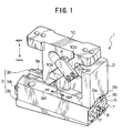
- a cam unit 1 comprises a cam driver 10 to be mounted to an upper movable mold tool, a cam slider 2 and a cam base 3 to be mounted to a lower stationary metal mold tool.
- the cam driver 10 has an inclined cam surface 10a.
- the cam slider 2 has an inclined surface, and is combined with the cam driver 10 with their inclined surfaces laid on each other, thereby permitting the cam slider 2 to move left or right as a counter action to the rising or lowering of the cam driver 10.
- the cam base 3 supports the cam slider 2 slidably.
- the cam base 3 has an inverted "V”-shaped upper surface with its ridge extending along the center longitudinal line of the cam base, running parallel to the sliding direction in which the cam slider 2 moves.
- the cam slider 2 has an inverted “V”-shaped bottom. The inverted “V”-shaped sliding bottom surface of the cam slider 2 rides closely on the inverted "V"-shaped top section of the cam base 3.
- cam slider 2 has oblique bottom surface halves 2a and 2b sloping up from its opposite longitudinal edges into its longitudinal center line, thus forming a roof-like sliding surface on its bottom side.
- the inclined cam surface 2d of the cam slider 2 is slidably laid on the inclined cam surface 10a of the cam driver 10.
- the cam slider 2 has tow forcedly returning followers 4 bolted to its opposite sides for jerking the cam slider 2 toward its original position subsequent to the cam action.
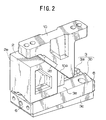
- the cam base 3 comprises a base body 3c to be bolted to the lower stationary mold tool, and two guide blocks 3a and 3b parallelarranged, leaving a longitudinal space therebetween, running in the sliding direction (see Fig.3).
- the guide blocks 3a and 3b has two reinforcement plates 6 bolted to their opposite ends.
- a spring pin rod 8 for a return spring appears on the reinforcement plate 6.
- each guide block 3a or 3b has an inclined top surface 3d or 3e, which slopes up from its outer longitudinal edge toward the top center line.
- the so formed roof-like shape is exactly same as the roof-like shape defined by the oblique bottom surface halves 2a and 2b of the cam slider 2.
- the self-centering means is provided.
- the parallel arrangement of two confronting guide blocks 3a and 3b with a given longitudinal space left therebetween makes it possible to reduce substantially the size of the cam base 3 in comparison with the overlying cam slider 2, accordingly permitting the saving of the material and weight of the cam base 3.
- the size from the front side to rear side, or width of the cam base 3 perpendicular to the direction in which the cam slider 2 slidably moves is substantially equal to that of the overlying cam slider 2.
- substantially equal is that the minimum difference therebetween is 10 millimeters or below.
- the rising and descending of the cam driver 10 will make the machining tool bearing cam slider 2 to move slidably on the cam base 3 without fear of the center deviation of the cam slider 2 which, otherwise, would be caused by the wearing of the sliding surfaces of the counter parts 2 and 3; the inverted "V"-shaped sliding surfaces will not cause any deviation of their center ridges even if a significant wearing is caused between the sliding surfaces of the counter parts 2 and 3.
- the inverted "V"-shaped surfaces of the counter sliding parts 2 and 3 will increase significantly their sliding areas over those of the horizontal surfaces of the counter sliding parts 11 and 12 (Figs.4a and 4b), accordingly increasing the resistance to the pressing force.
- the machining tool bearing area of the cam slider 2 can be increased by setting its dimension from front to rear side to be equal to the width of the cam base 3, thus permitting the fixing of machining tools of increased size.
- a cam unit equipped with self-centering means according to the present invention is guaranteed to be free of any decentering of the cam slider even if a significant wearing is caused between the sliding surfaces of the counter sliding parts.
- the inverted "V"-shaped forms of the counter sliding parts have the effect of increasing the area of the cam unit to which the pressing force is applied, and hence, increasing the resistance to the pressing force applied to the cam unit.
- the size from the front side to rear side or width of the cam base perpendicular to the direction in which the cam slider moves is substantially equal to that of the cam slider. This permits the machining tool bearing area of the cam slider to be increased significantly.
- the parallel arrangement of two confronting guide blocks with a given longitudinal space left therebetween makes it possible to reduce the weight of the whole cam unit to approximately one third of the weight of the conventional cam unit.
Landscapes
- Engineering & Computer Science (AREA)
- Mechanical Engineering (AREA)
- Mounting, Exchange, And Manufacturing Of Dies (AREA)
- Mechanical Treatment Of Semiconductor (AREA)
- Investigating Or Analysing Biological Materials (AREA)
- Bag Frames (AREA)
Priority Applications (4)
| Application Number | Priority Date | Filing Date | Title |
|---|---|---|---|
| DE2000612475 DE60012475T2 (de) | 2000-03-17 | 2000-03-17 | Selbstzentrierender Führungsschlitten |
| ES00105369T ES2222123T3 (es) | 2000-03-17 | 2000-03-17 | Unidad de leva equipada con medios de auto-centrado. |
| AT00105369T ATE271942T1 (de) | 2000-03-17 | 2000-03-17 | Selbstzentrierender führungsschlitten |
| EP00105369A EP1136151B1 (fr) | 2000-03-17 | 2000-03-17 | Coulisseau à auto-centrage |
Applications Claiming Priority (1)
| Application Number | Priority Date | Filing Date | Title |
|---|---|---|---|
| EP00105369A EP1136151B1 (fr) | 2000-03-17 | 2000-03-17 | Coulisseau à auto-centrage |
Publications (2)
| Publication Number | Publication Date |
|---|---|
| EP1136151A1 true EP1136151A1 (fr) | 2001-09-26 |
| EP1136151B1 EP1136151B1 (fr) | 2004-07-28 |
Family
ID=8168089
Family Applications (1)
| Application Number | Title | Priority Date | Filing Date |
|---|---|---|---|
| EP00105369A Expired - Lifetime EP1136151B1 (fr) | 2000-03-17 | 2000-03-17 | Coulisseau à auto-centrage |
Country Status (4)
| Country | Link |
|---|---|
| EP (1) | EP1136151B1 (fr) |
| AT (1) | ATE271942T1 (fr) |
| DE (1) | DE60012475T2 (fr) |
| ES (1) | ES2222123T3 (fr) |
Cited By (4)
| Publication number | Priority date | Publication date | Assignee | Title |
|---|---|---|---|---|
| EP1764168A1 (fr) * | 2005-09-20 | 2007-03-21 | Fibro GmbH | Ensemble coulisseau pour une camme arienne |
| EP1771263A4 (fr) * | 2004-07-27 | 2010-05-19 | Anchor Lamina America Inc | Cames étroite aérienne et montée sur matrice |
| CN102120242A (zh) * | 2010-01-08 | 2011-07-13 | 三协无油工业株式会社 | 凸轮装置 |
| EP1197319B2 (fr) † | 2000-10-13 | 2013-02-13 | voestalpine Giesserei Linz GmbH | Entraînement par coin |
Citations (3)
| Publication number | Priority date | Publication date | Assignee | Title |
|---|---|---|---|---|
| EP0484588A1 (fr) * | 1990-11-09 | 1992-05-13 | UMIX Co., Ltd. | Matrice avec coulisseau |
| US5904064A (en) * | 1997-02-25 | 1999-05-18 | Sankyo Oilless Industry, Inc. | Cam assembly for use in a pressing machine |
| EP0983808A1 (fr) * | 1998-08-26 | 2000-03-08 | Oiles Corporation | Système de commande à came de glissement |
-
2000
- 2000-03-17 ES ES00105369T patent/ES2222123T3/es not_active Expired - Lifetime
- 2000-03-17 DE DE2000612475 patent/DE60012475T2/de not_active Expired - Lifetime
- 2000-03-17 AT AT00105369T patent/ATE271942T1/de active
- 2000-03-17 EP EP00105369A patent/EP1136151B1/fr not_active Expired - Lifetime
Patent Citations (3)
| Publication number | Priority date | Publication date | Assignee | Title |
|---|---|---|---|---|
| EP0484588A1 (fr) * | 1990-11-09 | 1992-05-13 | UMIX Co., Ltd. | Matrice avec coulisseau |
| US5904064A (en) * | 1997-02-25 | 1999-05-18 | Sankyo Oilless Industry, Inc. | Cam assembly for use in a pressing machine |
| EP0983808A1 (fr) * | 1998-08-26 | 2000-03-08 | Oiles Corporation | Système de commande à came de glissement |
Cited By (5)
| Publication number | Priority date | Publication date | Assignee | Title |
|---|---|---|---|---|
| EP1197319B2 (fr) † | 2000-10-13 | 2013-02-13 | voestalpine Giesserei Linz GmbH | Entraînement par coin |
| EP1771263A4 (fr) * | 2004-07-27 | 2010-05-19 | Anchor Lamina America Inc | Cames étroite aérienne et montée sur matrice |
| EP1764168A1 (fr) * | 2005-09-20 | 2007-03-21 | Fibro GmbH | Ensemble coulisseau pour une camme arienne |
| CN102120242A (zh) * | 2010-01-08 | 2011-07-13 | 三协无油工业株式会社 | 凸轮装置 |
| CN102120242B (zh) * | 2010-01-08 | 2014-06-25 | 三协无油工业株式会社 | 凸轮装置 |
Also Published As
| Publication number | Publication date |
|---|---|
| DE60012475D1 (de) | 2004-09-02 |
| EP1136151B1 (fr) | 2004-07-28 |
| ATE271942T1 (de) | 2004-08-15 |
| ES2222123T3 (es) | 2005-02-01 |
| DE60012475T2 (de) | 2005-01-13 |
Similar Documents
| Publication | Publication Date | Title |
|---|---|---|
| EP0983808A1 (fr) | Système de commande à came de glissement | |
| JPH0244113B2 (fr) | ||
| KR101772752B1 (ko) | 부스바용 펀칭장치 | |
| EP1136151A1 (fr) | Coulisseau à auto-centrage | |
| JPH081243A (ja) | プレス金型装置 | |
| CN106180348A (zh) | 用于加工连续金属型材的加工站 | |
| AU2003217498B2 (en) | Apparatus for forming groove used in cutting blade | |
| KR20200125984A (ko) | 조정 가능한 안내 장치를 가진 웨지 구동부 | |
| KR20160129901A (ko) | 공구 이송대 | |
| JP3677931B2 (ja) | 搬送機構を備えた部品加工装置 | |
| JP3968806B2 (ja) | プレス金型用カム | |
| JP2007125619A (ja) | プレス金型用カム | |
| US6918333B2 (en) | Retainer device for a press punch | |
| JPH04167929A (ja) | 突上げ塑性加工装置 | |
| JP2002178087A (ja) | 圧造成形機 | |
| JPH0428650Y2 (fr) | ||
| KR20090029976A (ko) | 스테이지장치 | |
| JPH10286628A (ja) | ワークサポート装置 | |
| JP2002103394A (ja) | 射出成形装置 | |
| JPH0584597A (ja) | スクラツプのプレス・シヤー | |
| CN210679550U (zh) | 一种用于二次顶出的结构 | |
| CN223938566U (zh) | 一种钉扣机限位结构 | |
| CN222200285U (zh) | 一种模具定制加工用可调节快速夹持机构 | |
| US4653547A (en) | Guide for parts of a weaving machine | |
| JP2000135526A (ja) | カムユニット |
Legal Events
| Date | Code | Title | Description |
|---|---|---|---|
| PUAI | Public reference made under article 153(3) epc to a published international application that has entered the european phase |
Free format text: ORIGINAL CODE: 0009012 |
|
| AK | Designated contracting states |
Kind code of ref document: A1 Designated state(s): AT BE CH CY DE DK ES FI FR GB GR IE IT LI LU MC NL PT SE |
|
| AX | Request for extension of the european patent |
Free format text: AL;LT;LV;MK;RO;SI |
|
| 17P | Request for examination filed |
Effective date: 20011214 |
|
| AKX | Designation fees paid |
Free format text: AT BE CH CY DE DK ES FI FR GB GR IE IT LI LU MC NL PT SE |
|
| 17Q | First examination report despatched |
Effective date: 20030130 |
|
| GRAP | Despatch of communication of intention to grant a patent |
Free format text: ORIGINAL CODE: EPIDOSNIGR1 |
|
| GRAS | Grant fee paid |
Free format text: ORIGINAL CODE: EPIDOSNIGR3 |
|
| GRAA | (expected) grant |
Free format text: ORIGINAL CODE: 0009210 |
|
| AK | Designated contracting states |
Kind code of ref document: B1 Designated state(s): AT BE CH CY DE DK ES FI FR GB GR IE IT LI LU MC NL PT SE |
|
| PG25 | Lapsed in a contracting state [announced via postgrant information from national office to epo] |
Ref country code: CH Free format text: LAPSE BECAUSE OF FAILURE TO SUBMIT A TRANSLATION OF THE DESCRIPTION OR TO PAY THE FEE WITHIN THE PRESCRIBED TIME-LIMIT Effective date: 20040728 Ref country code: LI Free format text: LAPSE BECAUSE OF FAILURE TO SUBMIT A TRANSLATION OF THE DESCRIPTION OR TO PAY THE FEE WITHIN THE PRESCRIBED TIME-LIMIT Effective date: 20040728 Ref country code: FI Free format text: LAPSE BECAUSE OF FAILURE TO SUBMIT A TRANSLATION OF THE DESCRIPTION OR TO PAY THE FEE WITHIN THE PRESCRIBED TIME-LIMIT Effective date: 20040728 Ref country code: NL Free format text: LAPSE BECAUSE OF FAILURE TO SUBMIT A TRANSLATION OF THE DESCRIPTION OR TO PAY THE FEE WITHIN THE PRESCRIBED TIME-LIMIT Effective date: 20040728 Ref country code: BE Free format text: LAPSE BECAUSE OF FAILURE TO SUBMIT A TRANSLATION OF THE DESCRIPTION OR TO PAY THE FEE WITHIN THE PRESCRIBED TIME-LIMIT Effective date: 20040728 |
|
| REG | Reference to a national code |
Ref country code: GB Ref legal event code: FG4D |
|
| REG | Reference to a national code |
Ref country code: CH Ref legal event code: EP |
|
| REG | Reference to a national code |
Ref country code: IE Ref legal event code: FG4D |
|
| REF | Corresponds to: |
Ref document number: 60012475 Country of ref document: DE Date of ref document: 20040902 Kind code of ref document: P |
|
| PG25 | Lapsed in a contracting state [announced via postgrant information from national office to epo] |
Ref country code: GR Free format text: LAPSE BECAUSE OF FAILURE TO SUBMIT A TRANSLATION OF THE DESCRIPTION OR TO PAY THE FEE WITHIN THE PRESCRIBED TIME-LIMIT Effective date: 20041028 Ref country code: SE Free format text: LAPSE BECAUSE OF FAILURE TO SUBMIT A TRANSLATION OF THE DESCRIPTION OR TO PAY THE FEE WITHIN THE PRESCRIBED TIME-LIMIT Effective date: 20041028 Ref country code: DK Free format text: LAPSE BECAUSE OF FAILURE TO SUBMIT A TRANSLATION OF THE DESCRIPTION OR TO PAY THE FEE WITHIN THE PRESCRIBED TIME-LIMIT Effective date: 20041028 |
|
| NLV1 | Nl: lapsed or annulled due to failure to fulfill the requirements of art. 29p and 29m of the patents act | ||
| REG | Reference to a national code |
Ref country code: ES Ref legal event code: FG2A Ref document number: 2222123 Country of ref document: ES Kind code of ref document: T3 |
|
| REG | Reference to a national code |
Ref country code: CH Ref legal event code: PL |
|
| PG25 | Lapsed in a contracting state [announced via postgrant information from national office to epo] |
Ref country code: CY Free format text: LAPSE BECAUSE OF FAILURE TO SUBMIT A TRANSLATION OF THE DESCRIPTION OR TO PAY THE FEE WITHIN THE PRESCRIBED TIME-LIMIT Effective date: 20050317 Ref country code: IE Free format text: LAPSE BECAUSE OF NON-PAYMENT OF DUE FEES Effective date: 20050317 Ref country code: LU Free format text: LAPSE BECAUSE OF NON-PAYMENT OF DUE FEES Effective date: 20050317 |
|
| PG25 | Lapsed in a contracting state [announced via postgrant information from national office to epo] |
Ref country code: MC Free format text: LAPSE BECAUSE OF NON-PAYMENT OF DUE FEES Effective date: 20050331 |
|
| ET | Fr: translation filed | ||
| PLBE | No opposition filed within time limit |
Free format text: ORIGINAL CODE: 0009261 |
|
| STAA | Information on the status of an ep patent application or granted ep patent |
Free format text: STATUS: NO OPPOSITION FILED WITHIN TIME LIMIT |
|
| 26N | No opposition filed |
Effective date: 20050429 |
|
| REG | Reference to a national code |
Ref country code: IE Ref legal event code: MM4A |
|
| PG25 | Lapsed in a contracting state [announced via postgrant information from national office to epo] |
Ref country code: PT Free format text: LAPSE BECAUSE OF NON-PAYMENT OF DUE FEES Effective date: 20041228 |
|
| PGFP | Annual fee paid to national office [announced via postgrant information from national office to epo] |
Ref country code: FR Payment date: 20110401 Year of fee payment: 12 |
|
| PGFP | Annual fee paid to national office [announced via postgrant information from national office to epo] |
Ref country code: GB Payment date: 20110329 Year of fee payment: 12 |
|
| GBPC | Gb: european patent ceased through non-payment of renewal fee |
Effective date: 20120317 |
|
| REG | Reference to a national code |
Ref country code: FR Ref legal event code: ST Effective date: 20121130 |
|
| PG25 | Lapsed in a contracting state [announced via postgrant information from national office to epo] |
Ref country code: GB Free format text: LAPSE BECAUSE OF NON-PAYMENT OF DUE FEES Effective date: 20120317 Ref country code: FR Free format text: LAPSE BECAUSE OF NON-PAYMENT OF DUE FEES Effective date: 20120402 |
|
| PGFP | Annual fee paid to national office [announced via postgrant information from national office to epo] |
Ref country code: IT Payment date: 20190325 Year of fee payment: 20 Ref country code: DE Payment date: 20190321 Year of fee payment: 20 |
|
| PGFP | Annual fee paid to national office [announced via postgrant information from national office to epo] |
Ref country code: AT Payment date: 20190321 Year of fee payment: 20 |
|
| PGFP | Annual fee paid to national office [announced via postgrant information from national office to epo] |
Ref country code: ES Payment date: 20190418 Year of fee payment: 20 |
|
| REG | Reference to a national code |
Ref country code: DE Ref legal event code: R071 Ref document number: 60012475 Country of ref document: DE |
|
| REG | Reference to a national code |
Ref country code: AT Ref legal event code: MK07 Ref document number: 271942 Country of ref document: AT Kind code of ref document: T Effective date: 20200317 |
|
| REG | Reference to a national code |
Ref country code: ES Ref legal event code: FD2A Effective date: 20200903 |
|
| PG25 | Lapsed in a contracting state [announced via postgrant information from national office to epo] |
Ref country code: ES Free format text: LAPSE BECAUSE OF EXPIRATION OF PROTECTION Effective date: 20200318 |