EP1136158A1 - Porte plaquette de coupe et plaquette du rainurage - Google Patents
Porte plaquette de coupe et plaquette du rainurage Download PDFInfo
- Publication number
- EP1136158A1 EP1136158A1 EP01105620A EP01105620A EP1136158A1 EP 1136158 A1 EP1136158 A1 EP 1136158A1 EP 01105620 A EP01105620 A EP 01105620A EP 01105620 A EP01105620 A EP 01105620A EP 1136158 A1 EP1136158 A1 EP 1136158A1
- Authority
- EP
- European Patent Office
- Prior art keywords
- cutting
- insert holder
- insert
- spacer
- holder according
- Prior art date
- Legal status (The legal status is an assumption and is not a legal conclusion. Google has not performed a legal analysis and makes no representation as to the accuracy of the status listed.)
- Granted
Links
- 238000005520 cutting process Methods 0.000 title claims description 125
- 125000006850 spacer group Chemical group 0.000 claims abstract description 88
- 238000003780 insertion Methods 0.000 claims description 3
- 230000037431 insertion Effects 0.000 claims description 3
- 238000000034 method Methods 0.000 description 5
- 210000000078 claw Anatomy 0.000 description 4
- 238000000926 separation method Methods 0.000 description 3
- 238000005452 bending Methods 0.000 description 2
- 230000015572 biosynthetic process Effects 0.000 description 2
- 238000009434 installation Methods 0.000 description 2
- 230000009286 beneficial effect Effects 0.000 description 1
- 238000005352 clarification Methods 0.000 description 1
- 238000009826 distribution Methods 0.000 description 1
- 238000005553 drilling Methods 0.000 description 1
- 230000002349 favourable effect Effects 0.000 description 1
- 238000007373 indentation Methods 0.000 description 1
- 238000003754 machining Methods 0.000 description 1
- 238000004519 manufacturing process Methods 0.000 description 1
- 238000003801 milling Methods 0.000 description 1
- 230000007704 transition Effects 0.000 description 1
Images






Classifications
-
- B—PERFORMING OPERATIONS; TRANSPORTING
- B23—MACHINE TOOLS; METAL-WORKING NOT OTHERWISE PROVIDED FOR
- B23B—TURNING; BORING
- B23B27/00—Tools for turning or boring machines; Tools of a similar kind in general; Accessories therefor
- B23B27/08—Cutting tools with blade- or disc-like main parts
-
- B—PERFORMING OPERATIONS; TRANSPORTING
- B23—MACHINE TOOLS; METAL-WORKING NOT OTHERWISE PROVIDED FOR
- B23B—TURNING; BORING
- B23B29/00—Holders for non-rotary cutting tools; Boring bars or boring heads; Accessories for tool holders
- B23B29/04—Tool holders for a single cutting tool
- B23B29/043—Tool holders for a single cutting tool with cutting-off, grooving or profile cutting tools, i.e. blade- or disc-like main cutting parts
-
- Y—GENERAL TAGGING OF NEW TECHNOLOGICAL DEVELOPMENTS; GENERAL TAGGING OF CROSS-SECTIONAL TECHNOLOGIES SPANNING OVER SEVERAL SECTIONS OF THE IPC; TECHNICAL SUBJECTS COVERED BY FORMER USPC CROSS-REFERENCE ART COLLECTIONS [XRACs] AND DIGESTS
- Y10—TECHNICAL SUBJECTS COVERED BY FORMER USPC
- Y10T—TECHNICAL SUBJECTS COVERED BY FORMER US CLASSIFICATION
- Y10T407/00—Cutters, for shaping
- Y10T407/22—Cutters, for shaping including holder having seat for inserted tool
- Y10T407/2202—Plural spaced seats and common holder
-
- Y—GENERAL TAGGING OF NEW TECHNOLOGICAL DEVELOPMENTS; GENERAL TAGGING OF CROSS-SECTIONAL TECHNOLOGIES SPANNING OVER SEVERAL SECTIONS OF THE IPC; TECHNICAL SUBJECTS COVERED BY FORMER USPC CROSS-REFERENCE ART COLLECTIONS [XRACs] AND DIGESTS
- Y10—TECHNICAL SUBJECTS COVERED BY FORMER USPC
- Y10T—TECHNICAL SUBJECTS COVERED BY FORMER US CLASSIFICATION
- Y10T407/00—Cutters, for shaping
- Y10T407/25—Cutters, for shaping including cut off tool
-
- Y—GENERAL TAGGING OF NEW TECHNOLOGICAL DEVELOPMENTS; GENERAL TAGGING OF CROSS-SECTIONAL TECHNOLOGIES SPANNING OVER SEVERAL SECTIONS OF THE IPC; TECHNICAL SUBJECTS COVERED BY FORMER USPC CROSS-REFERENCE ART COLLECTIONS [XRACs] AND DIGESTS
- Y10—TECHNICAL SUBJECTS COVERED BY FORMER USPC
- Y10T—TECHNICAL SUBJECTS COVERED BY FORMER US CLASSIFICATION
- Y10T82/00—Turning
- Y10T82/10—Process of turning
-
- Y—GENERAL TAGGING OF NEW TECHNOLOGICAL DEVELOPMENTS; GENERAL TAGGING OF CROSS-SECTIONAL TECHNOLOGIES SPANNING OVER SEVERAL SECTIONS OF THE IPC; TECHNICAL SUBJECTS COVERED BY FORMER USPC CROSS-REFERENCE ART COLLECTIONS [XRACs] AND DIGESTS
- Y10—TECHNICAL SUBJECTS COVERED BY FORMER USPC
- Y10T—TECHNICAL SUBJECTS COVERED BY FORMER US CLASSIFICATION
- Y10T82/00—Turning
- Y10T82/25—Lathe
- Y10T82/2585—Tool rest
-
- Y—GENERAL TAGGING OF NEW TECHNOLOGICAL DEVELOPMENTS; GENERAL TAGGING OF CROSS-SECTIONAL TECHNOLOGIES SPANNING OVER SEVERAL SECTIONS OF THE IPC; TECHNICAL SUBJECTS COVERED BY FORMER USPC CROSS-REFERENCE ART COLLECTIONS [XRACs] AND DIGESTS
- Y10—TECHNICAL SUBJECTS COVERED BY FORMER USPC
- Y10T—TECHNICAL SUBJECTS COVERED BY FORMER US CLASSIFICATION
- Y10T82/00—Turning
- Y10T82/25—Lathe
- Y10T82/2585—Tool rest
- Y10T82/2591—Tool post
Definitions
- the present invention relates to an insert holder for turning tools. What is meant here in essentially a cutting insert holder for a lathe. Machining with turning is closed generally understood circular cutting movement. The chip removal takes place by a cutting movement against a linear feed movement of the tool perpendicular or parallel to the axis of rotation.
- the axis of rotation means the axis of rotation of the workpiece, when the workpiece rotates. With the workpiece stationary and the tool rotating, e.g. B. ring lathes, facing and boring tools with boring bars on drilling and milling machines, The axis of rotation must be understood as the axis of rotation of the rotating tool.
- Such insert holders are available in various designs on the market. There a cutting or grooving insert is generally inserted into the insert holder and with screwed this. Then the insert holder can be connected to the lathe. The insert holder is then carried out by the lathe to carry out the cutting process moved for example in the direction of the axis of the rotating workpiece, so that the im Insert holder fixed cutting insert engages with the workpiece and this, for example peeled or cut.
- the known insert holders have the disadvantage that, on the one hand, the replacement the cutting or grooving plate is very time-consuming and secondly, especially when a plurality of grooves are to be made in the workpiece, or a plurality of Slices are to be cut from the workpiece, the cutting process is very time-consuming is because the insert holder including the insert or cutting insert for each groove or each parting process must be moved individually in the feed direction.
- the insert is at these embodiments only after the adjustment of the insert securely in the insert holder held so that, particularly in the case of overhead mounting, the insert from the insert holder or the holding element can slip out or fall out.
- the present invention is therefore based on the object of providing an insert holder, that overcomes the disadvantages mentioned above.
- the insert holder is provided for this is to hold at least two lancing inserts.
- the at least two lancing inserts are in the held position is preferably arranged such that at least during the separation process temporarily at least two lancing inserts simultaneously with the rotating workpiece in Intervention. Because the insert holder can hold several lancing inserts and these can thus simultaneously move in the feed direction, the turning process can be significantly shortened become.
- every groove or parting process had to be carried out individually can be the same with the insert holder according to the invention a plurality of grooves or parting off operations are carried out in one process step.
- the lancing inserts are preferably held in the insert holder such that they are in the are essentially parallel to each other.
- the insert holder is particularly preferably designed such that it has at least two holding elements has, which are each provided for holding a lancing insert. As a result of that each lancing insert is held by its own holding element, is a simple change of one Part of the lancing insert possible.
- a particularly preferred embodiment provides that the holding elements in at least one Direction, preferably in the feed direction, are independently adjustable.
- the individual lancing inserts can be set independently of one another in the feed direction become. This makes it possible, for example, to use the insert holder at the same time Turn grooves of different depths into the workpiece. Those lancing inserts, which ones should create deeper grooves, together with their holding element, are simply compared to the others Grooving inserts shifted slightly in the feed direction.
- the insert holder expediently has a base body in which the holding elements are arranged, the holding elements being fixable in the base body.
- a particularly preferred embodiment provides that a clamping device for fixation the holding elements is arranged in the base body. By fixing with the clamping device the individual lancing insert can be picked up and fixed very quickly in the holding element. This ensures that the individual holding elements after adjustment in the feed direction can be fixed easily and quickly.
- the holding elements are particularly preferred by the Clamping device clamped in a direction that is perpendicular to the feed direction, preferably parallel to the axis of rotation.
- An embodiment of the insert holder is particularly expedient, in which the holding elements are interchangeable. This makes it possible to use either the holding elements including the lancing insert exchange, for example to have another lancing insert available quickly, or only to exchange a holding element and the lancing insert on the replaced holding element to assemble. This may be necessary, for example, if the clear distance between the different Lancing inserts should be changed, because then a holding element with a different width can be beneficial.
- the holding elements are preferably designed such that the cutting plates from the feed direction are inserted into the holding element.
- the insert holder is provided for this is, the lancing inserts in the axial direction or in the longitudinal direction in at least two positions hold.
- the axial direction is related to the rotating workpiece the direction of the workpiece axis. This measure allows the clear distance between two adjacent lancing inserts in the insert holder can be varied.
- the lancing inserts are essentially continuous axial direction can be varied so that it is securely fixed or in almost any position can be held. It is understood that such variability is not with a screw connection of the lancing insert can be realized with the holding element or the insert holder.
- a preferred embodiment therefore sees a clamping device for fixing the lancing inserts in the axial direction. With the help of this clamping device, after the lancing inserts adjusted, i.e. it is in the correct position both in the feed direction and in the axial direction have been brought, this position can be fixed easily and above all quickly.
- An expedient embodiment provides that at least one spacer is provided for this is to be fixed between two lancing inserts. Especially if not every lancing insert individually fixed or clamped to the holding element or in the insert holder it is advantageous if between two lancing inserts, the clear distance of which is a certain one Size exceeds, a spacer is placed. Then by the clamping device Lancing inserts clamped onto the spacer, so that a kind of sandwich clamping is created. The highly precise adjustment of the clear distance between the plug inserts is thus carried out by the Choice of the thickness of the spacer. Should the clear distance between two lancing inserts be increased If so, the use of another spacer or alternatively several Spacers necessary.
- the holding elements are provided for the To support or carry the lancing insert essentially in three points.
- the lancing insert is first inserted into the holding element such that it touches the holding element at the three points.
- the position of the lancing insert in relation to the holding element is precise due to the three points given.
- the fixing or clamping device then fixes the lancing insert in exactly this position.
- the three points need not actually be points, but usually display precisely machined partial surfaces, preferably on the edge surfaces.
- the holding element then supports or carries the lancing insert essentially on three partial surfaces.
- each holding element may have a fastening device for fixing a lancing insert in or on the holding element.
- a fastening device can also be a screw connection.
- the fixation of each individual lancing insert can the holding element be advantageous.
- Insert holder can be used.
- a particularly suitable cutting plate has a main part and at least one cutting part having a cutting edge, the at least one cutting part has a substantially constant width. It is understood that also a cutting part, which bevels only in the area of the cutting edge, for example has, in order to possibly achieve a more favorable distribution of the cutting forces, an essentially has constant width.
- the cutting inserts according to the invention described here can also be used with advantage in other insert holders.
- a cutting insert with a square basic shape and four cutting edges is particularly preferred.
- the cutting plate has two side surfaces or also main surfaces as well as several edge or edge surfaces, the cutting edges on the edge surfaces are arranged.
- the piercing plate preferably has one on at least one side edge Indentation or recess.
- a holding element which has a has the recess of the grooved plate adapted seat. This allows the insert are placed with their recess on the holding seat of the holding element, so that "automatically” gives the exact position of the lancing insert in relation to the holding element.
- the recesses can be realized in many ways, for example the edge surfaces of the Grooving plate be concavely curved at the recesses. However, it is understood that the edge surfaces do not necessarily have to be curved, but also, for example, essentially V-shaped can be trained.
- a special embodiment of the piercing plate provides at least two recesses.
- the holding element has a plate seat with not only a correspondingly shaped one Surface, but two bulges, which are adapted to the recesses of the cutting plate. So it is possible to insert the grooving plate even more precisely into the holding element, since the holding element is now and the grooving plate engage in a coordinated manner on two surfaces.
- the main part of the piercing plate particularly preferably has a greater width than at least that a cutting part.
- the width of the main part By varying the width of the main part, the clear distance between two adjacent inserts can be varied without using a spacer that the width of the cutting part and thus the width of the groove to be cut changes.
- the cutting part does not necessarily have to sit centrally on the main part.
- the cutting part z. B. can also be arranged on the main part such that on one side the insert has the surface of the main part and the surface of the cutting part in one plane, while on the other side of the insert the surface of the cutting part and the surface of the Main part are in parallel planes, so that a transition from the main part to the cutting part Stage arises.
- the cutting plate preferably has a cutting edge with a rake face and a free face, the rake face and free face enclose an angle ⁇ which is less than 90 °.
- the cutting edge particularly preferably has a chamfer.
- a concavely curved section can be provided which allows the chip formation and the chip flow favored.
- the insert is particularly preferably designed such that it is inserted into the insert holder used state is oriented such that a positive rake angle or angle of attack during of the separation process results.
- a securing device which secures a grooving plate or a turning tool and / or a spacer in the tool seat, wherein the securing device has an elastic element which is arranged such that a Turning tool or a spacer only by exerting a force on the elastic element the tool seat can be inserted and / or removed from it.
- This is ensures that the insert holder is able to insert a insert or a turning tool and / or to hold a spacer in the tool seat in such a way that axial positioning or adjustment of the turning tool or the spacer is easily possible, but an accidental Fall out or slip out of the turning tool and / or the spacer the tool seat of the insert holder is prevented.
- the insert or spacer is therefore inserted into the tool seat of the insert holder while exerting a force.
- the elastic element on the turning tool or the spacer Apply force so that this does not come out of the tool seat essentially due to the increased frictional force can fall out, or the securing device can in a positioning notch Insert or engage the insert or the spacer, so that the insert or the Only remove the spacer from the tool seat by exerting a force on the elastic element and then can be removed. It is understood that such a safety device according to the invention advantageous for all insert holders with at least one tool seat for a turning tool or a spacer can be used.
- the elastic element has a spring.
- the securing device preferably has a sleeve in which the elastic element is arranged.
- a particularly expedient embodiment of the securing device provides that a contact element is available, which is provided with a turning tool or a spacer engage when this is inserted into the tool seat.
- the contact element can then easily choose the material and shape of the turning tool in terms of material selection and shape or the spacer or, if necessary, the positioning notch. Then comes when inserting the turning tool or the spacer into the tool seat the turning tool or the spacer in contact with the contact element.
- the contact element, which is connected to the elastic element is then against the spring force of the elastic Elements pressed out of its rest position.
- the contact element is preferably on the side of the elastic side facing the tool seat Elements arranged within the sleeve. It is useful if the sleeve itself tapered at least so far at its end facing the tool seat that the contact element cannot completely come out of the sleeve at the end facing the tool seat. In other words, the sleeve has a stop at one end, so that the contact element, if neither turning tool nor spacer are inserted in the insert seat, from which elastic element is pressed against the stop. When inserting the turning tool or the spacer then the contact element against the spring force a little into the sleeve and pushed away from the stop. The elastic element then exercises in the inserted state a force on the rotary tool or the spacer from the contact element, so that this cannot fall out of the tool seat.
- the contact element can advantageously be rotated or pivoted about at least one axis. This allows easy axial adjustment, while securing against falling out Guaranteed turning tool or the spacer from the insert holder or the holding element is.
- the contact element can be, for example, a ball, which by the force of Spring is pressed against the turning tool or the spacer and within the sleeve their own axis can be rotated.
- an adjustment device is provided with the force that is applied during the insertion and / or removal of the turning tool and / or the spacer in or out of the tool seat on the elastic element must be exercised, can be discontinued. This makes it possible to use the application adjust the holding force of the safety device.
- each turning tool and / or every turning tool is advantageous Spacer assigned a safety device. This ensures that each one Spacer or each individual turning tool in the insert holder or the holding element can be kept safe.
- the spacer and / or the Grooving plate has a positioning notch, which is provided with a securing device to engage.
- the turning tool or the cutting plate consists of a main part and at least one a cutting part having a cutting edge, the cutting plate also being a Has positioning notch, which is intended to be inserted into the insert holder Condition to engage with a safety device.
- the positioning notch is advantageously essentially in the region of a recess Side surface arranged.
- An embodiment of the piercing plate is particularly preferred which comprises several, preferably four, Has cutting edges, each cutting edge being assigned a positioning notch. This enables the cutting insert to be held securely in the cutting insert holder with each intended Orientation of the insert.
- the recesses are in the essentially V-shaped, with a positioning notch arranged only on one V-leg is.
- This arrangement of the positioning notch has the advantage of being accidental Incorrect insertion of the insert in the insert seat is prevented, since then the corresponding Position where the contact element of the securing device is located, no positioning notch located. Accordingly, with a suitable design of the cutting plate, the cutting plate becomes only held securely in the insert seat when the insert is arranged so that the cutting edge is arranged in the correct orientation.
- the reference number 1 shown with a piercing plate 1 according to the invention.
- the one with the The reference number 1 provided with a piercing plate has a square basic shape, which is indicated by the dashed lines Lines is indicated. It consists of a main part 2 and four cutting parts 3.
- the cutting parts 3 have a constant width d3, which is less than the width d2 of the main part 2.
- the Cutting plate 1 has four recesses or prismatic chambers 4. These prismatic chambers or recesses 4 extend to the main part 2.
- the prismatic chambers 4 are limited by the edge surfaces 7, 7 'and 7 ".
- the surface 7 has a narrow section, the width of which corresponds to the width d3 of the cutting part, and a slightly wider one Part whose width corresponds to the width d2 of the main part.
- the one with the reference number 7 " is the part of the cutting part.
- the rounded surface 7 makes the surfaces 7 and 7 "connected.
- the prismatic chambers 4 extend into the main part 2.
- the prismatic chambers are essentially V-shaped, the legs of the V-shape, so the surfaces 7 and 7 "preferably - as is the case in the embodiment shown - are inclined inward about an angle of 25 °. Close in the embodiment shown the surfaces 6 and 7 "also form an angle of approximately 25 °. However, it is for some applications conceivable to bend the free surface 6 relative to the basic shape without affecting the prismatic Chamber changes something.
- a cutting edge 25 is arranged on the cutting part 3.
- a rake face borders this (5, 5 ', 5 ") and a free surface 6.
- the cutting surface itself is in turn divided into the actual cutting surface 5, the chamfer 5 'and the rounded surface 5 ".
- the rounded surface 5" is used for chip formation and Chip flow.
- Rake face 5 and free face 6 form an angle ⁇ of less than 90 °.
- a piercing plate according to the invention is used in a holding element.
- the grooving plate has some differences from that shown in FIG. 1.
- Main part has a substantially central through hole, so that with The lancing insert 1 can be fastened to the holding element 8 with the aid of the screw 9.
- the cutting parts 3, which are less Have width d3 as the width of the main part d2 are not placed centrally, so that the Main part 2 on one side of the lancing insert protrudes more than the cutting parts 3 than on the other hand.
- the holding element has bulges corresponding to the recesses in the cutting insert, that define the insert seat.
- the recesses are designed so that the insert on points 10 ', 10 "and 10' '' on the holding element.
- This three-point support means that Position of the cutting plate in the plane of the cutting plate in relation to the holding element 8 clearly certainly.
- the cutting or lancing insert in principle can also touch the holding element at point 10 "".
- a force is exerted on the cutting plate 10 in the direction of the arrow during the separation process exercised so that the piercing plate at point 10 "" may no longer be on the holding element lies on.
- FIG. 3 shows an alternative embodiment of a holding element 8 '.
- the piercing plate 1 is not screwed to the holding element, rather the holding element has a kind of claw 13, which due to the recess 12 relative to the tool shank of Holding element 8 ', the seat and backrest has something to move (bending beam), so that with the help the screw 11, the claw 13 can be moved in the direction of the cutting insert 1.
- the lancing insert 1 in the holding element 8 ' is thus first of all used that the lancing insert 1 in contact with the holding element at said points occurs. Then the claw 13 is tightened with the screw 11, so that the insert 1 inside of the holding element 8 'is fixed.
- the bending beam one from the tool shank can also be used separate claws can be used.
- FIG. 4 shows a third embodiment of a holding element 8 ′′.
- This holding element too has a seat and a backrest, similar to a chair. Seat and backrest are preferred reshaped the shape of the prismatic chambers 4 of the lancing insert 1.
- the holding element 8 " has a functional opening 14, the purpose of which is explained below.
- a spacer 15 can be seen in a perspective view in FIG.
- This spacer 15 also has two prismatic chambers 17 which are shaped such that the spacer 15th can be positively placed on the holding element 8 ".
- the spacer 15 also has a functional bore 16, which is further below in connection with the bore 14 of the holding element 8 "will be explained.
- the spacer is here in the holding element 8" 15 and the insert 1 inserted. It can be clearly seen that the prismatic chambers or the recesses 4 of the cutting plate 1 are adapted to the shape of the seat and back of the holding element 8 " are.
- the spacer 15 is also adapted to the shape of the holding element 8 ′′ Embodiment are the functional bores 16 and 14 of the spacer 15 and the Holding element 2 "essentially” in alignment ". However, this does not mean that the spacer 15 on the Holding element 8 "is screwed tight. This can be advantageous for special applications be, but in general the function opening serves, for example, a rough attachment of the Spacer 15 on the holding element 8 ".
- a rough attachment is understood to mean that the spacer 15 is attached to the holding element 8 "in such a way that the spacer 15 is not can be completely removed from the holding element 8 ", but that the spacer 15 in the longitudinal direction or in the axial direction, which is indicated here by arrows, can be moved at least to a limited extent is.
- the clamping device 16 is shown in FIG.
- the clamping device 16 has in this embodiment a similar basic shape as the holding element 8 ". It is made so that the clamping device 16 can be used in place of a holding element 8 "in the insert holder Clamping device 16 has a wedge 17 which can be "wedged” with the aid of screw 18. By tightening the screw 18, the wedge 17 is moved such that it moves out of the housing 19 the clamping device 16 extends.
- the insert holder is shown in an open position.
- the insert holder consists of a base body 20.
- Various holding elements are in this base body 8 ".
- the devices 8" are equipped with the spacers 15 and the lancing inserts 1.
- the holding elements 8 can be adjusted individually in the feed direction. Connected to this is an individual adjustment option of the cutting plates in the holding elements 8 "1
- the insert is adjusted lengthways or axially using the spacers 15. So spacers 15 and cutting plates 1 are selected so that they are strung together have the desired clear distance between them.
- the clamping device 16 incorporated in the base body 20.
- the spring-loaded with the reference number 21 Scraper rods serve here to scrape off chips or chip rings and to hold the Spacers 15. However, they are generally not absolutely necessary.
- FIGS. 9 and 10 show the insert holder with the cover 23 attached. It will So first the holding elements 8 "are inserted with the cover 23 of the base body 20 open individual grooving plates 1 are then selected and together with the corresponding spacers 15 inserted into the holding elements 8 ". The holding elements can be moved in the feed direction, as indicated by the arrow in FIG. 8. Only when the inserts have the correct position both in the feed direction and in the axial direction Grooving plates 1 and the spacers 15 are compressed using the clamping device 16 and fixed. Finally, the holding elements 8 "are pressed together by the clamping screws 22 and adjusted. Finally, the cover 23 is placed on the base body 20 and screwed tight. The individual grooving plates 1 are now fixed in the desired manner.
- a plurality of cutting plates 1 are in series with the aid of the clamping device 16 and the spacers 15 clamped by friction but also by the prismatic Shape of the insert 1 held in the insert seat. Due to the adjustable holding elements 8 " an individual lancing depth can be set for each lancing plate 1.
- the spacers are connected to the adjustable brackets by spring-loaded screws.
- the adjustable holder are independent of the plate clamping by means of two screws inserted in the block and the cover fixed.
- the securing device 28 prevents this.
- the securing device 28 is shown in FIG. 11, among others.
- the holding element 8 " here has a bore 34 which extends up to the plate seat. In this hole 34 is the Security device 28 inserted or screwed.
- the securing device 28 exists here from a sleeve 30 in which a spring element 29 and a contact element designed as a ball 33 are included.
- the sleeve 30 is tapered at its end 32 facing the plate seat formed or has stops 32.
- the securing device 28 is arranged that the contact element 33 extends through the bore 34 into the plate seat.
- Is also 11 shows a spacer 15 inserted into the plate seat.
- the spacer 15 has two prismatic chambers 17 which are designed such that they approximately the contour of the Follow plate seat of the holding element 8 ". It can be clearly seen that the spacer 15 in the applied state exerts a force on the contact element 33 so that the spherical contact element 33 pressed somewhat against the spring force of the elastic element 29 into the bore 34 becomes. In the inserted state, the contact element 33 therefore exercises due to the tension Spring 29 a holding force on the spacer 15 so that it does not fall out of the seat can.
- the spacer has 15 a recess or positioning notch 27 which is arranged such that in the inserted State the contact element 33 engages in the positioning notch. This will make the force exerted by the contact element 33 on the spacer is somewhat reduced, since the Contact element 33 now come out a little further out of bore 34 in the direction of the insert seat can, however, it is only possible to remove the spacer from the insert seat, if the spherical contact element 33 again in the bore 34 against the spring force of the elastic element 29 is pressed.
- This embodiment has the advantage that the spacer 15 is now slightly in the longitudinal direction or in can be moved in the axial direction, an accidental falling out of the spacer 15 the plate seat but by the spherical contact element 33 of the securing device 28, the engages in the positioning notch 27 of the spacer 15, is effectively prevented.
- the securing device 28 has an external thread, which in an internal thread of the bore 34 engages.
- the screw head-like head 31 of the sleeve 30 can therefore be adjusted to what extent the securing element 28 or the sleeve 30 into the bore 34 should be screwed.
- the holding force which the securing device 28 or exerts the spherical contact element 33 on the spacer 15 or the piercing plate 1 can be set.
- FIG. 12 is a perspective view of a holding element 8 ′′ with a spacer attached 15 shown.
- the inner parts are normally in a perspective view are not visible, shown by dashed lines.
- the bore 34 extends in the direction of the plate seat or the spacer 15.
- the securing device 28 is inserted, which with its contact element 33 into the positioning notch 27 of the spacer 15 engages.
- the positioning notch 27 extends in the longitudinal direction over the entire width of the spacer 15.
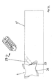
- FIG. 13 shows a holding element 8 ′′ with the securing device 28 according to the invention, wherein a piercing plate 1 is arranged in the insert seat of the holding element 8 ".
- the piercing plate also 1 has a positioning notch 26, which is provided for the contact element 33 of the securing device 28 engages in this positioning notch 26.
- Axial adjustability of the grooving plate is guaranteed while accidentally falling out or Preventing the cutting plate 1 from slipping out of the plate seat of the holding element 8 "
- the embodiment shown here exercises the contact element 33 in the position shown only one low holding force.
- the spherical contact element 33 must act against the spring force of the elastic element 29 are pressed into the bore 34 to take the cutting part out of the insert seat to be able to.
- the piercing plate 1 is shown enlarged again in FIG. 14.
- This representation corresponds to essential of the representation of Figure 1, here the four cutting parts 3 are made smaller.
- the positioning notch 26 is arranged in the region of the cutting part back 7 ′′.
- This arrangement of the positioning notch 26 has the additional advantage that an accidental Incorrect installation, that is, inserting the cutting plate 1 in an orientation in which not the intended cutting edge 25, but the free surface 6 is oriented in the cutting direction Grooving plate 1 does not "snap", since then the positioning notch 26 does not fit into the bore 34 "in Escape "can be brought so that the securing device 28 or the spherical contact element 33 can not engage with the positioning notch 26 and a secure hold of the Piercing plate 1 is not guaranteed within the plate seat of the holding element 8 ". In this case it is immediately determined during manual loading that the cutting plate 1 is not in the correct one Orientation is arranged so that the error can be corrected immediately. The functional and Process reliability of the lancing system is significantly improved.
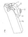
- FIGS. 15 and 16 show an alternative embodiment of the insert holder according to the invention shown with safety device. This differs from the embodiments the previous figures only in that the holding element 8 is not here with a Clamping device is provided, but the cutting plate with the aid of a screw on the holding element is attached. Accordingly, the embodiment shown in Figures 15 and 16 the piercing plate has a through hole located approximately in the center, which is used for fastening the piercing plate is used on the holding element.
- the mounting of the cutting plate is on the holding element due to the securing device 28 significantly simplified.
- the grooving plate 1 only has to be inserted into the insert seat until the securing device 28 "engages". in the Following this, the cutting plate can be screwed onto the holding element 8.
- the insert holder By means of the insert holder according to the invention, in one working step with a lathe Engage several turning tools with the workpiece at the same time. The manufacturing time can be shortened significantly. It is understood that the tool holder is not only with Parting tools can be used. In principle, all forms of turning tools are possible. By combining different widths of the main parts of the cutting inserts and / or different widths of spacers can be a variety of profiles on the workpiece generated quickly and easily.
Landscapes
- Engineering & Computer Science (AREA)
- Mechanical Engineering (AREA)
- Cutting Tools, Boring Holders, And Turrets (AREA)
- Turning (AREA)
- Jigs For Machine Tools (AREA)
Applications Claiming Priority (4)
| Application Number | Priority Date | Filing Date | Title |
|---|---|---|---|
| DE2000112821 DE10012821A1 (de) | 2000-03-16 | 2000-03-16 | Schneidplattenhalter für Drehwerkzeug sowie Stechplatte hierfür |
| DE10012821 | 2000-03-16 | ||
| DE10042779 | 2000-08-31 | ||
| DE2000142779 DE10042779A1 (de) | 2000-08-31 | 2000-08-31 | Schneidplattenhalter mit Sicherungseinrichtung sowie Stechplatte hierfür |
Publications (2)
| Publication Number | Publication Date |
|---|---|
| EP1136158A1 true EP1136158A1 (fr) | 2001-09-26 |
| EP1136158B1 EP1136158B1 (fr) | 2006-06-21 |
Family
ID=26004859
Family Applications (1)
| Application Number | Title | Priority Date | Filing Date |
|---|---|---|---|
| EP01105620A Expired - Lifetime EP1136158B1 (fr) | 2000-03-16 | 2001-03-07 | Porte plaquette de coupe et plaquette du rainurage |
Country Status (4)
| Country | Link |
|---|---|
| US (1) | US6612207B2 (fr) |
| EP (1) | EP1136158B1 (fr) |
| AT (1) | ATE330741T1 (fr) |
| DE (1) | DE50110198D1 (fr) |
Cited By (7)
| Publication number | Priority date | Publication date | Assignee | Title |
|---|---|---|---|---|
| FR2851185A1 (fr) * | 2003-02-17 | 2004-08-20 | Safety | Dispositif de bridage lateral de plaquette et plaquette pour un tel dispositif |
| FR2872723A1 (fr) * | 2004-07-12 | 2006-01-13 | Seco Tools Ab | Outil d'usinage notamment pour former une surface conique |
| WO2009082327A1 (fr) * | 2007-12-20 | 2009-07-02 | Seco Tools Ab | Plaquette de tournage amovible et outil de coupe comprenant une telle plaquette |
| DE102011007076A1 (de) | 2011-04-08 | 2012-10-11 | Walter Ag | Wendeschneidplatte und Wendeschneidplattenhalter |
| CN102905825A (zh) * | 2010-05-26 | 2013-01-30 | 伊斯卡有限公司 | 工具组件及其所用的具有弹性元件的工具架 |
| CN106457409A (zh) * | 2014-04-10 | 2017-02-22 | 伊斯卡有限公司 | 切削工具和用于该切削工具的具有正好四个切削部分的切削镶刀 |
| DE112022003414T5 (de) | 2021-07-05 | 2024-04-18 | Ortadogu Rulman Sanayi Ve Ticaret Anonim Sirketi | Andruckkraftvariabler beweglicher drehwerkzeughalter |
Families Citing this family (20)
| Publication number | Priority date | Publication date | Assignee | Title |
|---|---|---|---|---|
| IL152161A (en) * | 2002-02-19 | 2008-03-20 | Jacob Friedman | Metal cutting tool |
| EP1487607A1 (fr) * | 2002-02-21 | 2004-12-22 | Element Six (PTY) Ltd | Plaquette pour outil |
| AT6618U1 (de) * | 2002-08-16 | 2004-01-26 | Plansee Tizit Ag | Schneidwerkzeug zum drehen und bohren ins volle |
| USD526339S1 (en) * | 2005-11-09 | 2006-08-08 | Shanley Daniel B | Cutting insert for grooving operations |
| IL174670A (en) | 2006-03-30 | 2011-12-29 | Gil Hecht | Cutting Tools |
| KR101067161B1 (ko) * | 2010-01-06 | 2011-09-22 | 대구텍 유한회사 | 내경 그루브 가공용 절삭 인서트 및 그를 위한 툴홀더 |
| US8424468B2 (en) | 2010-07-01 | 2013-04-23 | Alan A Aden | Alternative pallet rail, pallet assembly, and method for making same |
| IL208826A (en) * | 2010-10-20 | 2016-02-29 | Iscar Ltd | Cutting tools and cutting tool for him |
| US8764351B2 (en) | 2012-09-13 | 2014-07-01 | Iscar, Ltd. | Cutting insert with flexibility aperture and cutting tool therefor |
| US9314851B2 (en) * | 2013-05-21 | 2016-04-19 | Iscar, Ltd. | Cutting insert having a rearwardly offset cutting edge and cutting tool |
| JP6462719B2 (ja) * | 2014-12-17 | 2019-01-30 | 京セラ株式会社 | 切削インサート、切削工具及び切削加工物の製造方法 |
| US10406605B2 (en) * | 2016-09-13 | 2019-09-10 | Iscar, Ltd. | Cutting tool having an indexable cutting insert retained by a moment force about a pivot axis |
| EP3378590A1 (fr) * | 2017-03-23 | 2018-09-26 | Seco Tools Ab | Ensemble d'inserts de coupe et procédés de fabrication d'un ensemble d'inserts de coupe |
| US10363722B2 (en) * | 2017-03-23 | 2019-07-30 | Iscar, Ltd. | Blade-shaped cutting insert and cutting tool therefor |
| JP6447892B1 (ja) * | 2017-06-23 | 2019-01-09 | 株式会社タンガロイ | 切削工具 |
| US11027342B2 (en) | 2019-03-27 | 2021-06-08 | Iscar, Ltd. | Double-sided cutting insert having diagonally opposed raised corners and diagonally opposed lowered corners, and rotary cutting tool |
| US11097362B2 (en) | 2019-12-10 | 2021-08-24 | Iscar, Ltd. | Cutting insert having two upper cutting edges and a lower central protuberance with four abutment walls defining an imaginary quadrilateral, and rotary cutting tool |
| CN111168093A (zh) * | 2020-03-04 | 2020-05-19 | 王天刚 | 一种防摔、抗震内孔车刀刀套 |
| US20250256335A1 (en) * | 2024-02-13 | 2025-08-14 | Iscar, Ltd. | Four-way indexable cutting insert and cutting tool |
| US20250269442A1 (en) * | 2024-02-28 | 2025-08-28 | Iscar, Ltd. | Cutting tool and indexable cutting insert having a plurality of circumferential cutting portions and a central mounting portion |
Citations (4)
| Publication number | Priority date | Publication date | Assignee | Title |
|---|---|---|---|---|
| US3163918A (en) * | 1962-11-19 | 1965-01-05 | U S Tool & Cutter Co | Grooving tool |
| DE2315044A1 (de) * | 1973-03-26 | 1974-10-10 | Hans Heinlein | Wendeplatte fuer spanabhebende werkzeuge |
| DE3241748A1 (de) * | 1982-11-11 | 1984-05-17 | James 4800 Bielefeld McKay | Vorrichtung zum einstechen von nuten in rotierende, spangebend zu bearbeitende werkstuecke |
| US4573832A (en) * | 1982-05-19 | 1986-03-04 | Firma Zinner Gmbh | Single and multiple recessing tool |
Family Cites Families (15)
| Publication number | Priority date | Publication date | Assignee | Title |
|---|---|---|---|---|
| US3078547A (en) * | 1957-04-22 | 1963-02-26 | Corlise M Sweet | Lathe cutting tools |
| US3922766A (en) * | 1972-08-15 | 1975-12-02 | Paul Malinchak | Inserts for metal cutters |
| US4243347A (en) * | 1979-02-28 | 1981-01-06 | General Electric Company | Broaching assembly having disposable carbide inserts |
| DE8406371U1 (de) | 1984-03-01 | 1984-05-30 | Oberhausen, Johannes, 6834 Ketsch | Stechwerkzeug mit auswechselbaren schneideinsaetzen |
| DE3442102A1 (de) | 1984-11-17 | 1986-06-12 | Zoltan 7770 Überlingen Berger | Spannschaft und dazugehoeriger schneidentraeger |
| US5119703A (en) * | 1988-06-01 | 1992-06-09 | Sandvik Ab | Cam shaft tool |
| SE463752B (sv) * | 1989-05-31 | 1991-01-21 | Reinar Schmidt | Utbytbart skaer foer gaengning och spaarstickning |
| SE502261C2 (sv) * | 1991-03-04 | 1995-09-25 | Sandvik Ab | Verktyg för skalsvarvning försett med polygonala grovskär och färdigskär |
| DE4126241A1 (de) * | 1991-08-08 | 1993-02-11 | Krupp Widia Gmbh | Schneideinsatz und bohrwerkzeug fuer bohrungen in vollmaterial |
| DE4240295A1 (en) | 1991-12-03 | 1993-06-09 | Ursula 7310 Plochingen De Groeschel | Clamp for securing throw-away tooltips in turning tool holder - has pulling ball clamp between depression in top face of tooltip and opposing thrust plate to seat tooltip in recess |
| US5205678A (en) * | 1992-08-27 | 1993-04-27 | Bucyrus-Erie Company | Gear cutting tool |
| DE9300465U1 (de) | 1993-01-15 | 1994-05-11 | Holler, Karl-Heinz, 61203 Reichelsheim | Schneidwerkzeug zur spanabhebenden Metallbearbeitung |
| DE19807498A1 (de) * | 1998-02-21 | 1999-09-02 | Horn P Hartmetall Werkzeugfab | Halter für spanabhebende Werkzeug-Einsätze |
| SE515222C2 (sv) * | 1998-04-07 | 2001-07-02 | Seco Tools Ab | Brotsch för spånavskiljande bearbetning |
| DE20017747U1 (de) | 2000-10-16 | 2000-12-28 | Holler, Karl-Heinz, 61203 Reichelsheim | Drehend antreibbares Schneidwerkzeug, insbesondere zum Fräsen oder Sägen |
-
2001
- 2001-03-07 DE DE50110198T patent/DE50110198D1/de not_active Expired - Lifetime
- 2001-03-07 EP EP01105620A patent/EP1136158B1/fr not_active Expired - Lifetime
- 2001-03-07 AT AT01105620T patent/ATE330741T1/de not_active IP Right Cessation
- 2001-03-16 US US09/809,166 patent/US6612207B2/en not_active Expired - Lifetime
Patent Citations (4)
| Publication number | Priority date | Publication date | Assignee | Title |
|---|---|---|---|---|
| US3163918A (en) * | 1962-11-19 | 1965-01-05 | U S Tool & Cutter Co | Grooving tool |
| DE2315044A1 (de) * | 1973-03-26 | 1974-10-10 | Hans Heinlein | Wendeplatte fuer spanabhebende werkzeuge |
| US4573832A (en) * | 1982-05-19 | 1986-03-04 | Firma Zinner Gmbh | Single and multiple recessing tool |
| DE3241748A1 (de) * | 1982-11-11 | 1984-05-17 | James 4800 Bielefeld McKay | Vorrichtung zum einstechen von nuten in rotierende, spangebend zu bearbeitende werkstuecke |
Cited By (13)
| Publication number | Priority date | Publication date | Assignee | Title |
|---|---|---|---|---|
| FR2851185A1 (fr) * | 2003-02-17 | 2004-08-20 | Safety | Dispositif de bridage lateral de plaquette et plaquette pour un tel dispositif |
| FR2872723A1 (fr) * | 2004-07-12 | 2006-01-13 | Seco Tools Ab | Outil d'usinage notamment pour former une surface conique |
| CN101903126B (zh) * | 2007-12-20 | 2012-12-05 | 山高刀具公司 | 可转位的车削刀片和包括这种刀片的切削刀具 |
| US7972090B2 (en) | 2007-12-20 | 2011-07-05 | Seco Tools Ab | Indexable turning insert and a cutting tool comprising such an insert |
| WO2009082327A1 (fr) * | 2007-12-20 | 2009-07-02 | Seco Tools Ab | Plaquette de tournage amovible et outil de coupe comprenant une telle plaquette |
| KR101506058B1 (ko) * | 2007-12-20 | 2015-03-25 | 쎄코 툴스 에이비 | 인덱서블 선삭 인서트 및 이러한 인서트를 포함하는 절삭 공구 |
| CN102905825A (zh) * | 2010-05-26 | 2013-01-30 | 伊斯卡有限公司 | 工具组件及其所用的具有弹性元件的工具架 |
| DE102011007076A1 (de) | 2011-04-08 | 2012-10-11 | Walter Ag | Wendeschneidplatte und Wendeschneidplattenhalter |
| WO2012136600A1 (fr) | 2011-04-08 | 2012-10-11 | Walter Ag | Plaquette de coupe amovible et support de plaquette de coupe amovible |
| US9457409B2 (en) | 2011-04-08 | 2016-10-04 | Walter Ag | Indexable cutting insert and indexable cutting insert holder |
| CN106457409A (zh) * | 2014-04-10 | 2017-02-22 | 伊斯卡有限公司 | 切削工具和用于该切削工具的具有正好四个切削部分的切削镶刀 |
| CN106457409B (zh) * | 2014-04-10 | 2018-10-19 | 伊斯卡有限公司 | 切削工具和用于该切削工具的具有正好四个切削部分的切削镶刀 |
| DE112022003414T5 (de) | 2021-07-05 | 2024-04-18 | Ortadogu Rulman Sanayi Ve Ticaret Anonim Sirketi | Andruckkraftvariabler beweglicher drehwerkzeughalter |
Also Published As
| Publication number | Publication date |
|---|---|
| DE50110198D1 (de) | 2006-08-03 |
| US20010022123A1 (en) | 2001-09-20 |
| EP1136158B1 (fr) | 2006-06-21 |
| ATE330741T1 (de) | 2006-07-15 |
| US6612207B2 (en) | 2003-09-02 |
Similar Documents
| Publication | Publication Date | Title |
|---|---|---|
| EP1136158B1 (fr) | Porte plaquette de coupe et plaquette du rainurage | |
| EP0282090B1 (fr) | Fraise à plaquettes | |
| EP0674560B1 (fr) | Outil de forage a piece de coupe rapportee interchangeable | |
| EP0884124B1 (fr) | Fraise avec ajustement axial | |
| DE2339873C2 (de) | Anordnung zum Einstellen und Befestigen eines ein Schneidplättchen tragenden Blocks in einer nutförmigen Aufnahme im Werkzeugkörper eines spanabhebenden Werkzeugs | |
| EP0674561A1 (fr) | Foret plein | |
| DE2145795A1 (de) | Schneidwerkzeug | |
| DE3215633A1 (de) | Fraeswerkzeug | |
| EP3458214B1 (fr) | Support pour un outil pour usinage, en particulier pour un outil de tournage | |
| CH624865A5 (fr) | ||
| EP0116260A2 (fr) | Dispositif pour fixer un objet | |
| EP3741483A1 (fr) | Plaquette de coupe, porte-plaquette et dispositif de coupe | |
| DE69923362T2 (de) | Werkzeug zur spanabhebenden Bearbeitung | |
| DE3622638C2 (fr) | ||
| EP2895289B1 (fr) | Outil d'usinage de pièces par enlèvement de matière | |
| DE2533495C3 (de) | Bohrstange | |
| EP0693013B1 (fr) | Systeme modulaire d'outil | |
| DE2112092A1 (de) | Werkzeughalter | |
| DE2602334A1 (de) | Raeumwerkzeug | |
| EP0033086B1 (fr) | Outil de perçage avec plaquette indexable | |
| EP1718430A2 (fr) | Procede d'usinage par enlevement de copeaux de trous de precision | |
| EP3954482B1 (fr) | Système d'outil | |
| DE10042779A1 (de) | Schneidplattenhalter mit Sicherungseinrichtung sowie Stechplatte hierfür | |
| DE19937738B4 (de) | Profil-Drehwerkzeug | |
| DE2906840C3 (de) | Aufbohrwerkzeug |
Legal Events
| Date | Code | Title | Description |
|---|---|---|---|
| PUAI | Public reference made under article 153(3) epc to a published international application that has entered the european phase |
Free format text: ORIGINAL CODE: 0009012 |
|
| AK | Designated contracting states |
Kind code of ref document: A1 Designated state(s): AT BE CH CY DE DK ES FI FR GB GR IE IT LI LU MC NL PT SE TR Kind code of ref document: A1 Designated state(s): AT DE FR GB IT SE |
|
| AX | Request for extension of the european patent |
Free format text: AL;LT;LV;MK;RO;SI |
|
| 17P | Request for examination filed |
Effective date: 20020130 |
|
| AKX | Designation fees paid |
Free format text: AT DE FR GB IT SE |
|
| 17Q | First examination report despatched |
Effective date: 20050304 |
|
| RAP1 | Party data changed (applicant data changed or rights of an application transferred) |
Owner name: SANDVIK INTELLECTUAL PROPERTY HB |
|
| RAP1 | Party data changed (applicant data changed or rights of an application transferred) |
Owner name: SANDVIK INTELLECTUAL PROPERTY AB |
|
| GRAP | Despatch of communication of intention to grant a patent |
Free format text: ORIGINAL CODE: EPIDOSNIGR1 |
|
| GRAS | Grant fee paid |
Free format text: ORIGINAL CODE: EPIDOSNIGR3 |
|
| GRAA | (expected) grant |
Free format text: ORIGINAL CODE: 0009210 |
|
| AK | Designated contracting states |
Kind code of ref document: B1 Designated state(s): AT DE FR GB IT SE |
|
| PG25 | Lapsed in a contracting state [announced via postgrant information from national office to epo] |
Ref country code: IT Free format text: LAPSE BECAUSE OF FAILURE TO SUBMIT A TRANSLATION OF THE DESCRIPTION OR TO PAY THE FEE WITHIN THE PRESCRIBED TIME-LIMIT;WARNING: LAPSES OF ITALIAN PATENTS WITH EFFECTIVE DATE BEFORE 2007 MAY HAVE OCCURRED AT ANY TIME BEFORE 2007. THE CORRECT EFFECTIVE DATE MAY BE DIFFERENT FROM THE ONE RECORDED. Effective date: 20060621 |
|
| REG | Reference to a national code |
Ref country code: GB Ref legal event code: FG4D Free format text: NOT ENGLISH |
|
| REF | Corresponds to: |
Ref document number: 50110198 Country of ref document: DE Date of ref document: 20060803 Kind code of ref document: P |
|
| REG | Reference to a national code |
Ref country code: SE Ref legal event code: TRGR |
|
| GBT | Gb: translation of ep patent filed (gb section 77(6)(a)/1977) |
Effective date: 20060816 |
|
| ET | Fr: translation filed | ||
| PLBE | No opposition filed within time limit |
Free format text: ORIGINAL CODE: 0009261 |
|
| STAA | Information on the status of an ep patent application or granted ep patent |
Free format text: STATUS: NO OPPOSITION FILED WITHIN TIME LIMIT |
|
| 26N | No opposition filed |
Effective date: 20070322 |
|
| PG25 | Lapsed in a contracting state [announced via postgrant information from national office to epo] |
Ref country code: AT Free format text: LAPSE BECAUSE OF NON-PAYMENT OF DUE FEES Effective date: 20070307 |
|
| REG | Reference to a national code |
Ref country code: FR Ref legal event code: PLFP Year of fee payment: 15 |
|
| PGFP | Annual fee paid to national office [announced via postgrant information from national office to epo] |
Ref country code: DE Payment date: 20150305 Year of fee payment: 15 Ref country code: IT Payment date: 20150225 Year of fee payment: 15 |
|
| PGFP | Annual fee paid to national office [announced via postgrant information from national office to epo] |
Ref country code: GB Payment date: 20150304 Year of fee payment: 15 Ref country code: FR Payment date: 20150309 Year of fee payment: 15 Ref country code: SE Payment date: 20150311 Year of fee payment: 15 |
|
| REG | Reference to a national code |
Ref country code: DE Ref legal event code: R119 Ref document number: 50110198 Country of ref document: DE |
|
| REG | Reference to a national code |
Ref country code: SE Ref legal event code: EUG |
|
| GBPC | Gb: european patent ceased through non-payment of renewal fee |
Effective date: 20160307 |
|
| PG25 | Lapsed in a contracting state [announced via postgrant information from national office to epo] |
Ref country code: SE Free format text: LAPSE BECAUSE OF NON-PAYMENT OF DUE FEES Effective date: 20160308 |
|
| REG | Reference to a national code |
Ref country code: FR Ref legal event code: ST Effective date: 20161130 |
|
| PG25 | Lapsed in a contracting state [announced via postgrant information from national office to epo] |
Ref country code: FR Free format text: LAPSE BECAUSE OF NON-PAYMENT OF DUE FEES Effective date: 20160331 Ref country code: GB Free format text: LAPSE BECAUSE OF NON-PAYMENT OF DUE FEES Effective date: 20160307 Ref country code: DE Free format text: LAPSE BECAUSE OF NON-PAYMENT OF DUE FEES Effective date: 20161001 |
|
| PG25 | Lapsed in a contracting state [announced via postgrant information from national office to epo] |
Ref country code: IT Free format text: LAPSE BECAUSE OF NON-PAYMENT OF DUE FEES Effective date: 20160307 |