EP1136172A2 - Vorrichtung zum Ausrichten und Schweissen von Blechen eines Kastenträgers, insbesondere eines Hauptträgers für Krane - Google Patents
Vorrichtung zum Ausrichten und Schweissen von Blechen eines Kastenträgers, insbesondere eines Hauptträgers für Krane Download PDFInfo
- Publication number
- EP1136172A2 EP1136172A2 EP01250071A EP01250071A EP1136172A2 EP 1136172 A2 EP1136172 A2 EP 1136172A2 EP 01250071 A EP01250071 A EP 01250071A EP 01250071 A EP01250071 A EP 01250071A EP 1136172 A2 EP1136172 A2 EP 1136172A2
- Authority
- EP
- European Patent Office
- Prior art keywords
- box girder
- sheets
- magnets
- welding
- longitudinal direction
- Prior art date
- Legal status (The legal status is an assumption and is not a legal conclusion. Google has not performed a legal analysis and makes no representation as to the accuracy of the status listed.)
- Withdrawn
Links
Images

Classifications
-
- B—PERFORMING OPERATIONS; TRANSPORTING
- B23—MACHINE TOOLS; METAL-WORKING NOT OTHERWISE PROVIDED FOR
- B23K—SOLDERING OR UNSOLDERING; WELDING; CLADDING OR PLATING BY SOLDERING OR WELDING; CUTTING BY APPLYING HEAT LOCALLY, e.g. FLAME CUTTING; WORKING BY LASER BEAM
- B23K37/00—Auxiliary devices or processes, not specially adapted for a procedure covered by only one of the other main groups of this subclass
- B23K37/04—Auxiliary devices or processes, not specially adapted for a procedure covered by only one of the other main groups of this subclass for holding or positioning work
- B23K37/0426—Fixtures for other work
- B23K37/0435—Clamps
-
- B—PERFORMING OPERATIONS; TRANSPORTING
- B23—MACHINE TOOLS; METAL-WORKING NOT OTHERWISE PROVIDED FOR
- B23K—SOLDERING OR UNSOLDERING; WELDING; CLADDING OR PLATING BY SOLDERING OR WELDING; CUTTING BY APPLYING HEAT LOCALLY, e.g. FLAME CUTTING; WORKING BY LASER BEAM
- B23K2101/00—Articles made by soldering, welding or cutting
- B23K2101/28—Beams
Definitions
- Box girders made up of three or four sheets, e.g. a horizontal one Sheet as lower chord and two sheets parallel to each other as Side plates as well as a horizontal plate as a top chord, are in particular as Main beam used for cranes.
- the two belt and To weld side panels in pairs using fillet welds. This requires exact prior alignment, which is usually done so that the for example, 30-meter-long sheets previously arranged in the box girder Cross bulkheads are roughly aligned.
- the Transverse bulkheads welded to the inside surfaces of the sheets.
- Transverse bulkheads used in the longitudinal direction of the box girders.
- the electromagnets are arranged on the corners of the production frame Box girder provided opposite welding devices with which the previously fine-aligned sheets in the course of the route of the Manufacturing frames are welded together using fillet welds.
- the manufacturing framework is then, i.e. after inactivation of the electromagnets proceed step by step.
- the disadvantage of the known device is that, despite the Transverse bulkheads must be additionally tacked beforehand, i.e. on individual along the metal sheets are spaced apart before the actual welding of the Fillet welds at the edges joined together by welding (stapled). This takes up a significant part of the manufacturing time. Further these stitching points are then welded over, which affects the quality of the Welds reduced.
- the object of the invention is to provide a device in which the stitching of the Sheets can be omitted before welding.
- the solution provides for rotatably mounted magnetic rollers, so that the operations Alignment and welding with continuous movement of the production frame can take place, a previous tacking of the sheets is no longer necessary.
- the magnetic rollers also act as holding elements, that run during the welding process and the sheets continuously align. As a result, stapling can be completely eliminated.
- An advantageous embodiment provides that the magnets designed as rollers Are electromagnets that can be easily switched off, which has the advantage that there is no need to shield the magnetic fields when not in use.
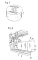
- Fig. 1 shows a device for aligning and welding box girders 7 (s. Fig. 3), which are used in particular as the main support for cranes.
- the Box girder 7 consists of four sheets 8, two vertical side sheets 8a, one horizontal sheet 8c resting on the upper edges of the two side sheets 8a as a top flange and a horizontal plate 8d as a bottom flange.
- the four sheets 8 are initially by means of Cross bulkheads connected by welding, which is a rough alignment corresponds to the sheet 8 which can still be precisely aligned.
- the production frame 1 consists of two in the longitudinal direction of the rail spaced U-shaped stimulation elements 3, which are above by means of two parallel Side members 4 are connected to each other. Parallel to the longitudinal beams 4 are in Inside the production frame 1 in two parallel vertical planes below and halfway up two further longitudinal beams 5, two opposite each other and at the same height, which each have three magnets 6 designed as rollers (Fig. 2) have a vertical axis of rotation. The magnets 6 protrude with their running surfaces laterally out of the outer contour of the side members 5. As shown in Fig. 1, the mutually facing magnets 6 facing each other in pairs, the light Distance of each magnet pair in each case the predetermined external distance Side plates 8a of the box girder 7 corresponds.
- Welding devices (not shown), by means of which the sheets 8 are attached in a known manner the corners of the box girder 7 can be welded together by means of basement seams.
- the welding devices can also be fixed on the production frame 1.
- the production frame 1 is over the drove away, for example, 30-meter box girder 7, its webbing 8c, 8d and side plates 8a roughly aligned with one another by means of the transverse bulkheads are connected, the rolling on the outer sides of the side plates 8a Magnets 6, the side plates 8a by means of the strong magnetic Fine-tune the attraction at the same time.
- the magnets 6 take over here Holding function, so that the four sheets 8 during the continuous process of Manufacturing frame 1 at the corners 8b, 8e of the box girder 7 by means of downstream welding devices are continuously welded together.
Landscapes
- Physics & Mathematics (AREA)
- Optics & Photonics (AREA)
- Engineering & Computer Science (AREA)
- Mechanical Engineering (AREA)
- Butt Welding And Welding Of Specific Article (AREA)
- Conveying And Assembling Of Building Elements In Situ (AREA)
Abstract
Description
- Fig. 1
- einen Fertigungsrahmen zum Ausrichten und Schweißen von Blechen eines Kastenträgers mittels als Rollen ausgebildeter Magnete,
- Fig. 2
- einen Magnet gemäß Fig. 1 und
- Fig. 3
- einen Kastenträger vor dem Ausrichten und Schweißen.
- 1
- Fertigungsrahmen
- 2
- Schiene
- 3
- Element
- 4
- Längsträger
- 5
- Längsträger
- 6
- Magnet
- 7
- Kastenträger
- 8
- Blech
- 8a
- Seitenblech
- 8b
- Ecke des Kastenträgers
- 8c
- Obergurt
- 8d
- Untergurt
- 8e
- Ecke des Kastenträgers
Claims (3)
- Vorrichtung zum Ausrichten und Schweißen von drei oder vier Blechen, einem horizontalen Blech als Untergurt und zwei parallel oder schräg zueinander verlaufenden Blechen als Seitenbleche, eines Kastenträgers mit rechteckigem bzw. dreieckigem Querschnitt, insbesondere eines Hauptträgers für Krane, der mindestens zwei in Kastenträgerlängsrichtung beabstandete, an den Innenseitenflächen der Bleche angeschweißte plattenförmige Querschotten aufweist,dadurch gekennzeichnet, dass die Magnete (6) als im Fertigungsrahmen (1) drehgelagerte Rollen ausgebildet sind, deren Drehachsen jeweils in einer Ebene quer zur Kastenträgerlängsrichtung liegen und bezogen auf die ausgerichteten Seitenbleche (8a) parallel zu dem unmittelbar gegenüberliegenden Seitenblech (8a) verlaufen.mit einem nach unten offenen U-förmigen Fertigungsrahmen, der auf zwei parallelen Schienen zwangsgeführt über den Kastenträger hinweg in Kastenträgerlängsrichtung verfahrbar ist und der längs- und/oder vertikalbeabstandete, den Seitenblechen unmittelbar gegenüberliegende und zumindest zeitweise aktivierbare Magnete trägt, die im aktiven Zustand die Seitenbleche mittels magnetischer Anziehungskräfte im Verlauf des Fahrweges jeweils ausrichten, undmit mehreren am Fertigungsrahmen angeordneten, den Ecken des Kastenträgers jeweils gegenüberliegenden und den Magneten in Fahrtrichtung nachgeordneten Schweißvorrichtungen, mittels derer die Bleche im Verlauf des Fahrweges jeweils mittels Kehlnähten miteinander paarweise verschweißbar sind,
- Vorrichtung nach Anspruch 1,
dadurch gekennzeichnet, dass die Magnete (6) als Elektromagnete ausgebildet sind. - Vorrichtung nach einem der Ansprüche 2 oder 3,
dadurch gekennzeichnet, dass die Magnete (6) nur längsbeabstandet angeordnet sind.
Applications Claiming Priority (4)
| Application Number | Priority Date | Filing Date | Title |
|---|---|---|---|
| DE10013227 | 2000-03-13 | ||
| DE10013227 | 2000-03-13 | ||
| DE10036366 | 2000-07-18 | ||
| DE10036366A DE10036366C2 (de) | 2000-03-13 | 2000-07-18 | Vorrichtung zum Ausrichten und Schweißen von Blechen eines Kastenträgers, insbesondere eines Hauptträgers für Krane |
Publications (2)
| Publication Number | Publication Date |
|---|---|
| EP1136172A2 true EP1136172A2 (de) | 2001-09-26 |
| EP1136172A3 EP1136172A3 (de) | 2002-10-02 |
Family
ID=26004883
Family Applications (1)
| Application Number | Title | Priority Date | Filing Date |
|---|---|---|---|
| EP01250071A Withdrawn EP1136172A3 (de) | 2000-03-13 | 2001-03-06 | Vorrichtung zum Ausrichten und Schweissen von Blechen eines Kastenträgers, insbesondere eines Hauptträgers für Krane |
Country Status (2)
| Country | Link |
|---|---|
| EP (1) | EP1136172A3 (de) |
| CZ (1) | CZ2001911A3 (de) |
Cited By (2)
| Publication number | Priority date | Publication date | Assignee | Title |
|---|---|---|---|---|
| CN111267016A (zh) * | 2020-03-16 | 2020-06-12 | 安徽大地熊新材料股份有限公司 | 一种磁料对接工装及对接方法 |
| CN111434439A (zh) * | 2019-01-15 | 2020-07-21 | 唐山开元自动焊接装备有限公司 | 一种龙门拼对点焊机构 |
Family Cites Families (6)
| Publication number | Priority date | Publication date | Assignee | Title |
|---|---|---|---|---|
| US3712529A (en) * | 1970-09-16 | 1973-01-23 | Nippon Kokan Kk | Movable welding jig |
| SE368924B (de) * | 1973-03-14 | 1974-07-29 | Esab Hebe Ab | |
| DE2749187C2 (de) * | 1976-11-11 | 1984-05-10 | Total Transportation Systems (International) A/S, Os | Vorrichtung zum Zuführen, Positionieren und Nachrichten von Profilen für das Heftschweißen der Profile an Platten o.dgl. |
| DE19548616C2 (de) * | 1995-03-07 | 2000-11-30 | Ingenieurtechnik Und Maschb Gm | Verfahren und Vorrichtung zum Aufsetzen und Schweißen von Profilen auf Blechplatten |
| DE19511098C1 (de) * | 1995-03-25 | 1996-04-11 | Thyssen Industrie | Verfahren zum kontinuierlichen Stumpfnahtschweißen von Blechtafeln, insbesondere im Karosseriebau der Kfz-Industrie, und Vorrichtung zum Durchführen dieses Verfahrens |
| EP1057580A1 (de) * | 1999-05-26 | 2000-12-06 | Sat Spa | Vorrichtung zum Stumpf-Laserschweissen von Blechen (VORBESTIMMTEN ZUSCHNITTEN), die magnetische Rollen hat, um die Bleche zur Schweissposition zu bewegen und die aktive Klemmen hat, um die Bleche zu klemmen |
-
2001
- 2001-03-06 EP EP01250071A patent/EP1136172A3/de not_active Withdrawn
- 2001-03-13 CZ CZ2001911A patent/CZ2001911A3/cs unknown
Cited By (3)
| Publication number | Priority date | Publication date | Assignee | Title |
|---|---|---|---|---|
| CN111434439A (zh) * | 2019-01-15 | 2020-07-21 | 唐山开元自动焊接装备有限公司 | 一种龙门拼对点焊机构 |
| CN111434439B (zh) * | 2019-01-15 | 2023-10-13 | 唐山开元自动焊接装备有限公司 | 一种焊接大型箱梁用的拼对点焊机构 |
| CN111267016A (zh) * | 2020-03-16 | 2020-06-12 | 安徽大地熊新材料股份有限公司 | 一种磁料对接工装及对接方法 |
Also Published As
| Publication number | Publication date |
|---|---|
| EP1136172A3 (de) | 2002-10-02 |
| CZ2001911A3 (cs) | 2001-10-17 |
Similar Documents
| Publication | Publication Date | Title |
|---|---|---|
| DE60020075T2 (de) | Verbindungsvorrichtung | |
| AT390111B (de) | Schalung zur errichtung von baukoerpern aus gussfaehigen materialien, wie beispielsweise beton | |
| DE3838488A1 (de) | Schaltafel | |
| DE4240970A1 (de) | Verfahren zum Fügen von flächig aufeinanderliegenden Blechen, Blechteilen oder Platten | |
| DE2656178A1 (de) | Einrichtung zum verbinden von pontons | |
| DE2850545A1 (de) | I-foermiges traegerprofil aus leichtmetall | |
| EP3712351B1 (de) | Tragstruktur für ein rahmenschalungspaneel | |
| EP0002814B2 (de) | Betonschalung aus Schaltafeln mit Keilverbindung | |
| DE10036366C2 (de) | Vorrichtung zum Ausrichten und Schweißen von Blechen eines Kastenträgers, insbesondere eines Hauptträgers für Krane | |
| EP0023373B1 (de) | Profileisen zur Verwendung als Gurt oder Ständer in Fachwerkträgern und ähnlichen Baustrukturen | |
| EP1136172A2 (de) | Vorrichtung zum Ausrichten und Schweissen von Blechen eines Kastenträgers, insbesondere eines Hauptträgers für Krane | |
| EP0596207A1 (de) | Blechprofil, vorzugsweise in kaltgewalzter Ausführung, zum erstellen von Traggerüsten, Bühnen und dgl. | |
| DE69517964T2 (de) | Rahmen | |
| EP0210577A1 (de) | Klemmvorrichtung mit einem Stützkörper | |
| DE3716833A1 (de) | Verfahren zur herstellung von vorgespannten stahltraegern, sowie die hierdurch erhaltenen traeger | |
| DE843424C (de) | Bruecke oder brueckenaehnliches Tragwerk aus genormten Einzelteilen | |
| DE4412005A1 (de) | Maschinenteil | |
| DE2423589C3 (de) | Vorrichtung zum Befestigen eines Kolonnenbodens in Stoffaustauschkolonnen | |
| DE842212C (de) | Aus Flachtaschen aufgebauter Waermeaustauscher | |
| DE7719315U1 (de) | Stahltraeger fuer grosse belastungen | |
| DE2415856A1 (de) | Keilverbindung fuer schaltafeln o.dgl. | |
| DE69108816T2 (de) | Verbesserte modulare Stützvorrichtung. | |
| EP0945210B1 (de) | Schweissverfahren zum Verbinden von Profilträgern, insbesondere von Lamellen für Fahrbahn-Übergangs-konstruktionen | |
| DE2850939A1 (de) | Vorrichtung zur halterung von kraftgeraeten zum geraderichten einer karosserie und oder eines fahrgestelles eines fahrzeuges, beispielsweise eines kraftfahrzeuges | |
| DE2263728C3 (de) | Stützenabschnitt und Tragstütze eines Metallgerüstes, insbesondere eines Kesselgerüstes |
Legal Events
| Date | Code | Title | Description |
|---|---|---|---|
| PUAI | Public reference made under article 153(3) epc to a published international application that has entered the european phase |
Free format text: ORIGINAL CODE: 0009012 |
|
| AK | Designated contracting states |
Kind code of ref document: A2 Designated state(s): AT BE CH CY DE DK ES FI FR GB GR IE IT LI LU MC NL PT SE TR |
|
| AX | Request for extension of the european patent |
Free format text: AL;LT;LV;MK;RO;SI |
|
| RIN1 | Information on inventor provided before grant (corrected) |
Inventor name: CORREDERA, RAUL, DIPL.-ING. Inventor name: POESEL, HERBERT, DIPL.-ING. Inventor name: SCHULZ, CHRISTOPH, DIPL.-ING. Inventor name: DORNHOEFER, KLAUS, DIPL.-ING. |
|
| PUAL | Search report despatched |
Free format text: ORIGINAL CODE: 0009013 |
|
| AK | Designated contracting states |
Kind code of ref document: A3 Designated state(s): AT BE CH CY DE DK ES FI FR GB GR IE IT LI LU MC NL PT SE TR |
|
| AX | Request for extension of the european patent |
Free format text: AL;LT;LV;MK;RO;SI |
|
| AKX | Designation fees paid | ||
| REG | Reference to a national code |
Ref country code: DE Ref legal event code: 8566 |
|
| STAA | Information on the status of an ep patent application or granted ep patent |
Free format text: STATUS: THE APPLICATION IS DEEMED TO BE WITHDRAWN |
|
| 18D | Application deemed to be withdrawn |
Effective date: 20030403 |