EP1136186A2 - Sperrklinke für einen Schraubschlüssel des Ratschen-Typs - Google Patents
Sperrklinke für einen Schraubschlüssel des Ratschen-Typs Download PDFInfo
- Publication number
- EP1136186A2 EP1136186A2 EP00122394A EP00122394A EP1136186A2 EP 1136186 A2 EP1136186 A2 EP 1136186A2 EP 00122394 A EP00122394 A EP 00122394A EP 00122394 A EP00122394 A EP 00122394A EP 1136186 A2 EP1136186 A2 EP 1136186A2
- Authority
- EP
- European Patent Office
- Prior art keywords
- ratchet
- hole
- pawl
- teeth
- ratchet gear
- Prior art date
- Legal status (The legal status is an assumption and is not a legal conclusion. Google has not performed a legal analysis and makes no representation as to the accuracy of the status listed.)
- Withdrawn
Links
Images


Classifications
-
- B—PERFORMING OPERATIONS; TRANSPORTING
- B25—HAND TOOLS; PORTABLE POWER-DRIVEN TOOLS; MANIPULATORS
- B25B—TOOLS OR BENCH DEVICES NOT OTHERWISE PROVIDED FOR, FOR FASTENING, CONNECTING, DISENGAGING, OR HOLDING
- B25B13/00—Spanners; Wrenches
- B25B13/46—Spanners; Wrenches of the ratchet type, for providing a free return stroke of the handle
- B25B13/461—Spanners; Wrenches of the ratchet type, for providing a free return stroke of the handle with concentric driving and driven member
- B25B13/462—Spanners; Wrenches of the ratchet type, for providing a free return stroke of the handle with concentric driving and driven member the ratchet parts engaging in a direction radial to the tool operating axis
- B25B13/463—Spanners; Wrenches of the ratchet type, for providing a free return stroke of the handle with concentric driving and driven member the ratchet parts engaging in a direction radial to the tool operating axis a pawl engaging an externally toothed wheel
Definitions
- the present invention relates to a pawl for a ratchet-type spanner to provide reliable ratcheting.
- the ratchet-type spanner includes a handle 1' with a box end 11' for rotatably receiving a ratchet gear 2' that is mounted between a ring-like cover plate 6' and a ledge 8' and retained in place by a C-clip 7'.
- a side of the box end 11' is drilled to form a hole 12' that extends along an axis at an angle of ⁇ (12° ⁇ 18°) with a horizontal axis of the box end 11'.
- a pawl 3' is mounted in the hole 12' and includes ratchet teeth 31' formed on a side thereof for releasably engaging with teeth 21' of the ratchet gear 2' and a compartment 32' defined in the other side thereof.
- a spring 4' is mounted in the compartment 32' for biasing the pawl 3' to engage with the teeth 21'.
- a threaded plug 5' is mounted in the hole 12' and engaged with an inner threading 121' of the hole 12'.
- the plug 5' includes an inner side 51' for retaining the spring 4' and the pawl 3' in place and an outer side with a hexagonal recess 52'.
- the present invention is intended to provide a buckle device that mitigates and/or obviate the above problems.
- a ratchet-type spanner comprises:
- the first end of the pawl includes a beveled face that faces the inner periphery of the slant hole.
- the web includes an inclined indication area for indicating ratcheting direction of the ratchet-type spanner by an inclination direction of the inclined indication area.
- the plug includes at least one knurl formed on an outer periphery thereof, the knurl being in force-fitting engagement with the inner periphery defining the slant hole.
- An inner periphery defining the hole of the box end includes a first annular groove.
- the outer periphery of the ratchet gear includes a second annular groove facing the first annular groove. A C-clip is received in the first annular groove and the second annular groove for rotatably retaining the ratchet gear in the hole of the box end.
- a ratchet-type spanner comprises:
- a ratchet-type spanner comprises:
- a ratchet-type spanner comprises:
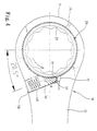
- a ratchet-type spanner 10 in accordance with the present invention generally includes a handle 12 and a box end 11 having a hole 111.
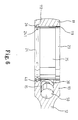
- An inner periphery (not labeled) defining the hole 111 of the box end 11 includes an annular groove 112 in a lower portion thereof.
- the annular groove 12 is formed simultaneously when the box end 11 is formed by a cutting tool.
- a web 13 is defined between the box end 11 and the handle 12 and has an inclined indication area 14 for indicating ratcheting direction of the spanner by the inclination direction of the inclined indication area 14.
- a slant hole 15 is defined in the web 13 and includes an inner end communicated with the hole 111 of the box end 11 and an outer end communicated with outside. The slant hole 15 extends along an axis that is at an angle (preferably 18.5°) with a normal to a longitudinal axis of the box end, as shown in Fig. 3.
- a ratchet gear 20 is mounted in the box end 11 and includes an inner periphery 21 for driving a fastener (not shown) and an outer periphery 22.
- the outer periphery 22 includes an upper end portion 23, a lower end portion 24, and a middle portion with a plurality of recessed ratchet teeth 25.
- the lower end portion 24 includes an annular groove 241.
- a C-clip 26 is received in the annular groove 241 of the lower end portion 24 and the annular groove 112 of the box end 11, thereby rotatably retaining the ratchet gear 20 in the box end 11 of the spanner 10, best shown in Fig. 6.
- a substantially cylindrical pawl 30 is mounted in the slant hole 15 in the web 13 and includes ratchet teeth 31 on an end thereof for engaging with ratchet teeth 25 of the ratchet gear 20.
- the end of the ratchet 31 further includes a beveled face 32, which will be described later.
- An elastic member 40 is also mounted in the slant hole 15 in the web 13 and includes an end attached to the other end of the pawl 30.
- the other end of the elastic member 40 is attached to a plug 50 that is securely mounted in the outer end of the hole 15 in the web 13.
- the other side of the pawl 30 has a recess 33 (Fig.
- the plug 50 includes at least one knurl 51 formed on an outer periphery thereof for retaining the plug 50 in place by force-fitting engagement with an inner periphery of the slant hole 15 in the web 13. Tolerance problem in the diameter of the slant hole 15 and the outer diameter of the plug 50 is eliminated by the force-fitting engagement between the knurl 51 and the inner periphery of the hole 15.
- the pawl 30 when not in use, the pawl 30 bears against the slant hole 15 at point A, and the beveled face 32 of the pawl 30 and the inner periphery of the slant hole 15 has a gap therebetween.
- the ratchet teeth 31 on the pawl 30 completely mesh with the concave ratchet teeth 25 of the ratchet gear 20. It is noted that the complete engagement between the teeth 31 and 25 occurs when the slant hole 15 extends along an axis that is at an angle of 18.5° with the normal to the longitudinal axis of the box end 11.
- the slant hole 15 does not extend along an axis that is at an angle of 18.5° with the normal to the longitudinal axis of the box end 11 due to tolerance in the processing precision.
- the slant hole 15 extends along an axis that is at an angle of 20.5° with the normal to the longitudinal axis of the box end 11
- the beveled face 32 of the pawl 30 and the inner periphery of the hole 15 has a gap therebetween.
- the spanner 10 is turned, the ratchet teeth 31 on the pawl 30 are subjected to a force F via transmission of the ratchet teeth 25 of the ratchet gear 20.
- the pawl 30 pivots about point A such that the beveled face 32 of the pawl 10 is in intimate contact with the inner periphery of the hole 15, thereby still providing complete engagement between the teeth 31 and 25.
- Fig. 5 illustrates a comparative example, wherein the pawl 30 has no beveled face 32 while the slant hole 15 extends along an axis that is at an angle of 20.5° with the normal to the longitudinal axis of the box end 11. It is apparent that the ratchet teeth 31 on the pawl 30 cannot engage with the ratchet teeth 25 of the ratchet gear 20 without provision of the beveled face 32 when the spanner 10 is turned. Thus, provision of the beveled face 32 on the pawl 30 may obviate manufacture tolerance of drilling the slant hole 15 in the web 13.
- the ratchet-type spanner in accordance with the present invention includes several advantages. Firstly, the inclined indication area 14 indicates the ratcheting direction of the spanner. Manufacture of the box end 11 is easier and inexpensive by means of directly forming the annular grooves 112 and 241, and the assembly procedure is easier, as the cover 6' and ledge 8' in the conventional design is not required.
- the protrusion 51 of the plug 50 may reliably retain the plug 50 in place and thus retain the pawl 30 and the elastic member 40 in place, and the tolerance problem is also obviated.
- the beveled face 32 of the pawl 30 may obviate manufacture tolerance of drilling the slant hole 15 in the web 13.
Landscapes
- Engineering & Computer Science (AREA)
- Mechanical Engineering (AREA)
- Details Of Spanners, Wrenches, And Screw Drivers And Accessories (AREA)
Applications Claiming Priority (2)
| Application Number | Priority Date | Filing Date | Title |
|---|---|---|---|
| US523624 | 1990-05-15 | ||
| US09/523,624 US6263767B1 (en) | 2000-01-19 | 2000-03-13 | Pawl for a ratchet-type spanner |
Publications (2)
| Publication Number | Publication Date |
|---|---|
| EP1136186A2 true EP1136186A2 (de) | 2001-09-26 |
| EP1136186A3 EP1136186A3 (de) | 2003-06-04 |
Family
ID=24085745
Family Applications (1)
| Application Number | Title | Priority Date | Filing Date |
|---|---|---|---|
| EP00122394A Withdrawn EP1136186A3 (de) | 2000-03-13 | 2000-10-26 | Sperrklinke für einen Schraubschlüssel des Ratschen-Typs |
Country Status (1)
| Country | Link |
|---|---|
| EP (1) | EP1136186A3 (de) |
Cited By (4)
| Publication number | Priority date | Publication date | Assignee | Title |
|---|---|---|---|---|
| DE10238803B4 (de) * | 2001-08-27 | 2004-09-09 | Bobby Hu | Verfahren zum Herstellen eines Ratschenringschlüssels |
| WO2012063122A3 (de) * | 2010-04-30 | 2014-07-17 | Wolf-Dietrich Zander | Anordnung oder werkzeug zum übertragen eines drehmoments |
| CN104949075A (zh) * | 2015-07-06 | 2015-09-30 | 江苏无畏警用装备制造有限公司 | 警用肩灯夹及其制作方法 |
| DE102017111158A1 (de) | 2017-05-22 | 2018-11-22 | Gedore-Werkzeugfabrik Gmbh & Co. Kg | Schraubwerkzeug |
Family Cites Families (3)
| Publication number | Priority date | Publication date | Assignee | Title |
|---|---|---|---|---|
| US2201827A (en) * | 1939-04-17 | 1940-05-21 | Otto P Froeschl | Ratchet mechanism |
| US4991468A (en) * | 1990-08-10 | 1991-02-12 | Lee Clark J | Barrel type sockets |
| DE29901793U1 (de) * | 1999-02-02 | 1999-04-01 | Hsieh, Chih-Ching, Fong Yuan, Taichung | Ratschensteckschlüssel |
-
2000
- 2000-10-26 EP EP00122394A patent/EP1136186A3/de not_active Withdrawn
Cited By (5)
| Publication number | Priority date | Publication date | Assignee | Title |
|---|---|---|---|---|
| DE10238803B4 (de) * | 2001-08-27 | 2004-09-09 | Bobby Hu | Verfahren zum Herstellen eines Ratschenringschlüssels |
| WO2012063122A3 (de) * | 2010-04-30 | 2014-07-17 | Wolf-Dietrich Zander | Anordnung oder werkzeug zum übertragen eines drehmoments |
| CN104949075A (zh) * | 2015-07-06 | 2015-09-30 | 江苏无畏警用装备制造有限公司 | 警用肩灯夹及其制作方法 |
| CN104949075B (zh) * | 2015-07-06 | 2017-10-27 | 无畏警用装备有限公司 | 警用肩灯夹及其制作方法 |
| DE102017111158A1 (de) | 2017-05-22 | 2018-11-22 | Gedore-Werkzeugfabrik Gmbh & Co. Kg | Schraubwerkzeug |
Also Published As
| Publication number | Publication date |
|---|---|
| EP1136186A3 (de) | 2003-06-04 |
Similar Documents
| Publication | Publication Date | Title |
|---|---|---|
| US6263767B1 (en) | Pawl for a ratchet-type spanner | |
| US6134990A (en) | Ratcheting tool with improved gear wheel/pawl engagement | |
| US7444904B2 (en) | Ratchet mechanism for ratchet tool | |
| US6971286B2 (en) | Ratcheting wrench with quick tightening/loosening functions and fine adjusting functions | |
| US6644148B2 (en) | Reversible ratchet-type wrench | |
| US6260448B1 (en) | Top load ratchet wrench | |
| US7178429B2 (en) | Easy-to-assemble ratcheting tool | |
| US6539825B1 (en) | Single direction ratcheting wrench with stuck prevention and ratcheting direction indication | |
| JP5059230B2 (ja) | タング無し螺旋状コイルインサート挿入工具 | |
| US20030070512A1 (en) | Reversible ratchet-type wrench | |
| US20020166416A1 (en) | Easy-to-operate and easy-to-assemble ratcheting-type wrench | |
| US6647832B2 (en) | Wrench having two rigid supporting areas for a pawl | |
| US20040139823A1 (en) | Biasing arrangement for a pawl of a reversible ratchet-type wrench | |
| US6968758B2 (en) | Wrench adaptor for driving screw driver bits | |
| US6601477B2 (en) | Wrench adaptor allowing reversible operation | |
| US20030079579A1 (en) | Wrench with a fixed maximum operational torque | |
| USRE42816E1 (en) | Dual function retainer for a ratcheting wrench | |
| US20020148332A1 (en) | Screwdriver shank with a universal joint | |
| US6752051B2 (en) | Wrench with a fixed maximum operational torque | |
| US5343786A (en) | Bit and socket combination | |
| US20040187648A1 (en) | Annular wrench | |
| US6609444B1 (en) | Switching lever for ratchet tools | |
| US20030010159A1 (en) | Biasing arrangement for a pawl of a reversible ratchet-type wrench | |
| US11103982B2 (en) | Wrench structure | |
| EP1136186A2 (de) | Sperrklinke für einen Schraubschlüssel des Ratschen-Typs |
Legal Events
| Date | Code | Title | Description |
|---|---|---|---|
| PUAI | Public reference made under article 153(3) epc to a published international application that has entered the european phase |
Free format text: ORIGINAL CODE: 0009012 |
|
| AK | Designated contracting states |
Kind code of ref document: A2 Designated state(s): AT BE CH CY DE DK ES FI FR GB GR IE IT LI LU MC NL PT SE |
|
| AX | Request for extension of the european patent |
Free format text: AL;LT;LV;MK;RO;SI |
|
| PUAL | Search report despatched |
Free format text: ORIGINAL CODE: 0009013 |
|
| AK | Designated contracting states |
Designated state(s): AT BE CH CY DE DK ES FI FR GB GR IE IT LI LU MC NL PT SE |
|
| AX | Request for extension of the european patent |
Extension state: AL LT LV MK RO SI |
|
| AKX | Designation fees paid |
Designated state(s): DE ES FR GB IT SE |
|
| STAA | Information on the status of an ep patent application or granted ep patent |
Free format text: STATUS: THE APPLICATION IS DEEMED TO BE WITHDRAWN |
|
| 18D | Application deemed to be withdrawn |
Effective date: 20031205 |