EP1136204A2 - Vorrichtung zum Durchtrennen von endlosen Profilen - Google Patents
Vorrichtung zum Durchtrennen von endlosen Profilen Download PDFInfo
- Publication number
- EP1136204A2 EP1136204A2 EP00105889A EP00105889A EP1136204A2 EP 1136204 A2 EP1136204 A2 EP 1136204A2 EP 00105889 A EP00105889 A EP 00105889A EP 00105889 A EP00105889 A EP 00105889A EP 1136204 A2 EP1136204 A2 EP 1136204A2
- Authority
- EP
- European Patent Office
- Prior art keywords
- profile
- knife
- longitudinal axis
- cutting
- movement
- Prior art date
- Legal status (The legal status is an assumption and is not a legal conclusion. Google has not performed a legal analysis and makes no representation as to the accuracy of the status listed.)
- Withdrawn
Links
- 238000005452 bending Methods 0.000 claims abstract description 4
- 238000005520 cutting process Methods 0.000 claims description 27
- 239000003000 extruded plastic Substances 0.000 claims 1
- 230000000149 penetrating effect Effects 0.000 abstract description 3
- 238000000926 separation method Methods 0.000 description 7
- 238000001125 extrusion Methods 0.000 description 6
- 238000000034 method Methods 0.000 description 5
- 230000000694 effects Effects 0.000 description 2
- 230000007704 transition Effects 0.000 description 2
- 238000011109 contamination Methods 0.000 description 1
- 230000003292 diminished effect Effects 0.000 description 1
- 230000002996 emotional effect Effects 0.000 description 1
- 239000002920 hazardous waste Substances 0.000 description 1
- 239000000463 material Substances 0.000 description 1
- 238000004064 recycling Methods 0.000 description 1
- 230000003068 static effect Effects 0.000 description 1
- 239000002699 waste material Substances 0.000 description 1
Images

Classifications
-
- B—PERFORMING OPERATIONS; TRANSPORTING
- B26—HAND CUTTING TOOLS; CUTTING; SEVERING
- B26D—CUTTING; DETAILS COMMON TO MACHINES FOR PERFORATING, PUNCHING, CUTTING-OUT, STAMPING-OUT OR SEVERING
- B26D1/00—Cutting through work characterised by the nature or movement of the cutting member or particular materials not otherwise provided for; Apparatus or machines therefor; Cutting members therefor
- B26D1/56—Cutting through work characterised by the nature or movement of the cutting member or particular materials not otherwise provided for; Apparatus or machines therefor; Cutting members therefor involving a cutting member which travels with the work otherwise than in the direction of the cut, i.e. flying cutter
- B26D1/60—Cutting through work characterised by the nature or movement of the cutting member or particular materials not otherwise provided for; Apparatus or machines therefor; Cutting members therefor involving a cutting member which travels with the work otherwise than in the direction of the cut, i.e. flying cutter and is mounted on a movable carriage
-
- B—PERFORMING OPERATIONS; TRANSPORTING
- B26—HAND CUTTING TOOLS; CUTTING; SEVERING
- B26D—CUTTING; DETAILS COMMON TO MACHINES FOR PERFORATING, PUNCHING, CUTTING-OUT, STAMPING-OUT OR SEVERING
- B26D1/00—Cutting through work characterised by the nature or movement of the cutting member or particular materials not otherwise provided for; Apparatus or machines therefor; Cutting members therefor
- B26D1/0006—Cutting members therefor
-
- B—PERFORMING OPERATIONS; TRANSPORTING
- B26—HAND CUTTING TOOLS; CUTTING; SEVERING
- B26D—CUTTING; DETAILS COMMON TO MACHINES FOR PERFORATING, PUNCHING, CUTTING-OUT, STAMPING-OUT OR SEVERING
- B26D7/00—Details of apparatus for cutting, cutting-out, stamping-out, punching, perforating, or severing by means other than cutting
- B26D7/08—Means for treating work or cutting member to facilitate cutting
- B26D7/14—Means for treating work or cutting member to facilitate cutting by tensioning the work
-
- B—PERFORMING OPERATIONS; TRANSPORTING
- B26—HAND CUTTING TOOLS; CUTTING; SEVERING
- B26D—CUTTING; DETAILS COMMON TO MACHINES FOR PERFORATING, PUNCHING, CUTTING-OUT, STAMPING-OUT OR SEVERING
- B26D1/00—Cutting through work characterised by the nature or movement of the cutting member or particular materials not otherwise provided for; Apparatus or machines therefor; Cutting members therefor
- B26D1/0006—Cutting members therefor
- B26D2001/0053—Cutting members therefor having a special cutting edge section or blade section
Definitions
- the invention relates to a device for severing endless profiles with a longitudinal axis, especially of extruded ones Plastic profiles, with a knife pointing in the direction of movement of the knife towards the profile and essentially perpendicular to the longitudinal axis is movable.
- DE 298 08 312 U1 therefore discloses a separating device which is equipped with a knife. This is guided in a frame, the side parts of the frame can be completely folded away. The knife is moved by a cylinder and can therefore not follow a movement profile.
- the invention is therefore based on the object of further developing the generic separating device which is equipped with a knife in such a way that it becomes possible to carry out a reproduced separating process. Furthermore, the aim is to ensure that the separation point has no bulge and that the profile has a perfect quality at the separation point.
- the achievement of the object by the invention is characterized by means (3, 4) for bending the profile (2) along its longitudinal axis (L) in the sectional area of the profile (2), the means (3, 4) by the bend in the generate a tensile stress on the area of the profile (2) facing the knife (5).
- the invention is based on the knowledge that in previously known Separating devices by the knife penetrating the profile is clamped with the profile lying on top, since not - as with one Saw - material is cut out, so there is no space for the knife.
- the invention counteracts the resulting clamping force.
- the means causing a bend (3, 4) such a bias on the side of the profile that the Knife is facing that the profile in the cutting area is no longer straight but by the pre-stress at an angle ( ⁇ ) is kept smaller than 180 °, for example between 150 ° and 180 °, before the cutting knife penetrates the profile.
- the means (3, 4) preferably consist of at least two hold-down devices (3) which rest on one side of the profile to be cut (2), as well as at least one increase (4) on the other side of the profile (2).
- the hold-down devices (3) are on the side of the profile (2) facing the knife (5). It can also help of cutting can be provided that the increase (4) in Area of the knife (5) is interrupted.
- the knife (5) is advantageously driven by a drive unit (10) moved, with particular thought of a servo motor with which a precisely controlled movement of the knife is possible.
- the design the drive unit as a servo motor therefore offers the advantage of a quick and precise control of the knife; the control of the knife can be integrated into the overall control of the extrusion process become.
- Another advantage of the digitally controllable servo motor is that that a speed profile of the knife can be driven because the cutting speed has a significant impact on quality who has separation.
- the course of the cut is further improved in that the first contact of the knife (5) with the profile (2) on an edge (6) of the profile (2); this reduces the cutting force required.
- the knife (5) is perpendicular to the longitudinal axis (L) of the profile (2) and perpendicular to the direction (R) of the knife (5) on the Profile (2) to an angle ( ⁇ ) of between 5 ° and 35 °, preferably at 25 °.
- the cutting edge (7) of the knife (5) in Direction (R) of the movement of the knife (5) on the profile (2) at least has two stages (8, 9).
- the angle ( ⁇ ) between the direction (R) of the movement of the knife (5) towards the profile (2) and the cutting surface in the area the step (8) is greater than the angle ( ⁇ ) between the direction (R) of Movement of the knife (5) towards the profile (2) and the cutting surface in the area of level (9).
- a profile can be separated without cutting during the extrusion process.
- the whole Device is mounted on a carriage which, during the actual cutting process is carried out, the clamped, i.e. pre-tensioned, Profile, at extrusion speed via a drive (here can e.g. an electric or pneumatic drive can be selected) emotional.
- a drive here can e.g. an electric or pneumatic drive can be selected
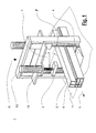
- the device 1 is shown schematically in FIG.
- the knife 5 is inserted in a receptacle and guide 12, which is mounted on a movable table 11.
- the hold-down devices 3 are also attached.
- To the knife 5 for the cutting process Moving in the direction R towards the profile 2 is a drive unit 10 mounted under the movable table 11.
- the device 1 is housed in a security housing 13.
- the whole Unit can be integrated into the extrusion line so that the profile 2 through a cutout 14 of the separating device 1 can. After a predetermined supply, this can be done using appropriate Measuring devices or determined after a certain time, the hold-down devices 3 are actuated, e.g. via one or more pneumatic cylinders.
- This hold-down 3 press the profile 2 against the movable Table 11. Due to the increase 4, the profile becomes a bending moment. This happens - as is clear from the Fig. 1 emerges - such that the part of the profile 2, the knife 5th is facing, is subject to tensile stress. Expressed differently: The hold-down 3 and the increase 4 make the profile 2 forced brought out of its stretched, flat position and partially under an angle ⁇ is kept smaller than 180 °. Now via the control The cutting process is released by means of the drive unit 10 driven knife 5 executed. Profile 2 is made by driving back the hold-down 3 and also by retracting the Knife 5 released again. The separated profile part is replaced by a removed further recess 14, for example with a gripper, which takes over the automatic stacking of the profiles, the table becomes 11 promoted to its starting position while feeding for the next Cut is already done.
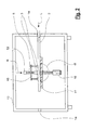
- FIG 2 is a perspective schematic view of the cutting unit to see.
- the holder is on the knife receptacle and guide 12 13 attached to the hold-down device 3 in such a way that this without great disassembly work, for example, can be folded away to be very easy to get to the knife 5, e.g. switch.
- the increase 4 is very clearly shown, over which the Prestressing of profile 2 after pressing it down by the hold-down device 3, not shown extended here, is generated.
- the angle ⁇ of the knife 5 the cutting process begins at one Edge 6 of profile 2.
- the extract from device 1 shown in FIG. 3 shows the knife 5 with the required angle ⁇ to start the profile 2 at the Cut edge 6.
- FIG. 7 An enlargement of the cutting edge 7 of the knife 5 can be seen in FIG. This clearly shows the different sizes of the two angles ⁇ and ⁇ of the two stages 8 and 9 of the cutting edge 7, the one homogeneous transition from the tip of the cutting edge 7 to the flanks of the Allow knife 5.
- the notch effect of the hitting profile 2 Knife 5 is hereby reduced.
Landscapes
- Life Sciences & Earth Sciences (AREA)
- Forests & Forestry (AREA)
- Engineering & Computer Science (AREA)
- Mechanical Engineering (AREA)
- Extrusion Of Metal (AREA)
- Control And Other Processes For Unpacking Of Materials (AREA)
- Apparatuses For Bulk Treatment Of Fruits And Vegetables And Apparatuses For Preparing Feeds (AREA)
- Processing Of Meat And Fish (AREA)
- Nonmetal Cutting Devices (AREA)
Abstract
Description
- Fig. 1
- zeigt schematisch die gesamte Vorrichtung, in
- Fig. 2
- ist der Schneidteil perspektivisch dargestellt,
- Fig. 3
- zeigt das Messer mit einem Profilquerschnitt und in
- Fig. 4
- ist der Querschnitt des Messers dargestellt.
- 1
- Vorrichtung
- 2
- Profil
- 3
- Niederhalter
- 4
- Erhöhung
- 5
- Messer
- 6
- Kante des Profils 2
- 7
- Schneide des Messers 5
- 8
- erste Stufe der Schneide 7
- 9
- zweite Stufe der Schneide 7
- 10
- Antriebseinheit
- 11
- verfahrbarer Tisch
- 12
- Messer-Aufnahme und -Führung
- 13
- Sicherheitsgehäuse
- 14
- Aussparung im Sicherheitsgehäuse 13
- 15
- Halterung für Niederhalter 3
- L
- Längsachse des Profils 2
- R
- Richtung des Messers 5 auf das Profil 2 zu
- α
- Winkel des Profils 2 im vorgespannten Zustand
- β
- Winkel des Messers 5
- δ
- Winkel der Stufe 8 zur Trennrichtung
- ϕ
- Winkel der Stufe 9 zur Trennrichtung
Claims (10)
- Vorrichtung zum Durchtrennen von endlosen Profilen (2) mit einer Längsachse (L), insbesondere von extrudierten Kunststoffprofilen, mit einem Messer (5), das in Richtung (R) der Bewegung des Messers (5) auf das Profil (2) zu und im wesentlichen senkrecht zur Längsachse (L) bewegbar ist,
gekennzeichnet durch
Mittel (3, 4) zum Biegen des Profils (2) entlang seiner Längsachse (L) im Schnittbereich des Profils (2), wobei die Mittel (3, 4) durch die Biegung in dem dem Messer (5) zugewandten Bereich des Profils (2) eine Zugspannung erzeugen. - Vorrichtung nach Anspruch 1, dadurch gekennzeichnet, daß die Mittel (3, 4) aus mindestens zwei Niederhaltern (3) bestehen, die auf einer Seite des zu durchtrennenden Profils (2) anliegen, sowie aus mindestens einer Erhöhung (4), die auf der anderen Seite des Profils (2) anliegen.
- Vorrichtung nach Anspruch 2, dadurch gekennzeichnet, daß die Niederhalter (3) an der Seite des Profils (2) anliegen, die dem Messer (5) zugewandt ist.
- Vorrichtung nach Anspruch 3, dadurch gekennzeichnet, daß die Erhöhung (4) im Bereich des Messers (5) unterbrochen ist.
- Vorrichtung nach einem der Ansprüche 1 bis 4, dadurch gekennzeichnet, daß das Messer (5) von einer Antriebseinheit (10) bewegt wird.
- Vorrichtung nach Anspruch 5, dadurch gekennzeichnet, daß die Antriebseinheit (10) einen Servomotor aufweist.
- Vorrichtung nach einem der Ansprüche 1 bis 6, dadurch gekennzeichnet, daß der erste Kontakt des Messers (5) mit dem Profil (2) an einer Kante (6) des Profils (2) erfolgt.
- Vorrichtung nach einem der Ansprüche 1 bis 7, dadurch gekennzeichnet, daß das Messer (5) senkrecht zur Längsachse (L) des Profils (2) und senkrecht zur Richtung (R) des Messers (5) auf das Profil (2) zu einen Winkel (β) aufweist, der zwischen 5° und 35°, vorzugsweise bei 25°, liegt.
- Vorrichtung nach einem der Ansprüche 1 bis 8, dadurch gekennzeichnet, daß die Schneide (7) des Messers (5) in Richtung (R) der Bewegung des Messers (5) auf das Profil (2) zu mindestens zwei Stufen (8, 9) aufweist.
- Vorrichtung nach Anspruch 9, dadurch gekennzeichnet, daß der Winkel (δ) zwischen der Richtung (R) der Bewegung des Messers (5) auf das Profil (2) zu und der Schneidenoberfläche im Bereich der Stufe (8) größer ist als der Winkel (ϕ) zwischen der Richtung (R) der Bewegung des Messers (5) auf das Profil (2) zu und der Schneidenoberfläche im Bereich der Stufe (9).
Applications Claiming Priority (2)
| Application Number | Priority Date | Filing Date | Title |
|---|---|---|---|
| DE29905169U DE29905169U1 (de) | 1999-03-20 | 1999-03-20 | Vorrichtung zum Durchtrennen von endlosen Profilen |
| DE29905169U | 2000-03-20 |
Publications (2)
| Publication Number | Publication Date |
|---|---|
| EP1136204A2 true EP1136204A2 (de) | 2001-09-26 |
| EP1136204A3 EP1136204A3 (de) | 2003-08-13 |
Family
ID=8071176
Family Applications (1)
| Application Number | Title | Priority Date | Filing Date |
|---|---|---|---|
| EP00105889A Withdrawn EP1136204A3 (de) | 1999-03-20 | 2000-03-20 | Vorrichtung zum Durchtrennen von endlosen Profilen |
Country Status (2)
| Country | Link |
|---|---|
| EP (1) | EP1136204A3 (de) |
| DE (1) | DE29905169U1 (de) |
Cited By (2)
| Publication number | Priority date | Publication date | Assignee | Title |
|---|---|---|---|---|
| EP1649988A1 (de) * | 2004-10-22 | 2006-04-26 | G. WACHSMUTH & CO. WERKZEUGBAU GmbH | Werkzeug zum Durchtrennen von Folien, insbesondere von mehrschichtigen Folien |
| CN103419223A (zh) * | 2013-08-29 | 2013-12-04 | 宁波禾采医疗器械有限公司 | 塑料切割机 |
Families Citing this family (6)
| Publication number | Priority date | Publication date | Assignee | Title |
|---|---|---|---|---|
| FR2783453B1 (fr) * | 1998-09-23 | 2000-11-24 | E3C | Procede et machine de coupe en continu de profiles en matiere plastique extrudee |
| EP1118437A1 (de) * | 2000-01-21 | 2001-07-25 | Crescent Manufacturing Company | Enthäutungsmesser |
| AT5545U1 (de) * | 2001-09-13 | 2002-08-26 | Technoplast Kunststofftechnik | Vorrichtung zum spanlosen trennen von kunststoffprofilen |
| DE102005049399A1 (de) * | 2005-10-13 | 2007-04-19 | Senator Technology Gmbh | Schneidvorrichtung |
| DE102005053376A1 (de) * | 2005-11-07 | 2007-05-10 | Battenfeld Extrusionstechnik Gmbh | Vorrichtung und Verfahren zum Abtrennen plastischer Massen |
| DE202012005943U1 (de) * | 2012-06-20 | 2013-09-25 | Stein Maschinenbau Gmbh & Co. Kg | Vorrichtung zum Ablängen von Kunststoffprofilen |
Family Cites Families (9)
| Publication number | Priority date | Publication date | Assignee | Title |
|---|---|---|---|---|
| US3232159A (en) | 1963-09-24 | 1966-02-01 | Parker Hannifin Corp | Portable hose cut-off means |
| CH453156A (de) | 1965-04-06 | 1968-05-31 | Loepfe Ag Geb | Trennvorrichtung für dünne längliche Gebilde und Verwendung derselben |
| DE2013282A1 (en) | 1970-03-20 | 1971-10-07 | Weber & Seelaender | Guillotine for plastic strand material |
| DE2408319C3 (de) | 1974-02-21 | 1980-02-07 | Hapri-Leichtbauplatten-Werk Herbert Prignitz, 2000 Hamburg | Schneidvorrichtung zum spanlosen Schneiden von Hartschaumstoffkörpern |
| US3978747A (en) * | 1975-03-24 | 1976-09-07 | The Gates Rubber Company | Method and apparatus for severing reinforced elastomeric tubular articles |
| FI63178C (fi) * | 1981-08-05 | 1983-05-10 | Jorma Lillbacka | Kapningsmaskin foer slangar |
| DE9110857U1 (de) | 1991-09-02 | 1991-10-10 | Roehm Gmbh, 6100 Darmstadt | Vorrichtung zum scharfkantigen Quertrennen einer extrudierten Hohlkammerbahn aus spröd-hartem thermoplastischem Kunststoff |
| DE29808312U1 (de) | 1998-05-11 | 1998-08-13 | cpm GmbH, 49124 Georgsmarienhütte | Trennmesser |
| FR2783453B1 (fr) * | 1998-09-23 | 2000-11-24 | E3C | Procede et machine de coupe en continu de profiles en matiere plastique extrudee |
-
1999
- 1999-03-20 DE DE29905169U patent/DE29905169U1/de not_active Expired - Lifetime
-
2000
- 2000-03-20 EP EP00105889A patent/EP1136204A3/de not_active Withdrawn
Cited By (2)
| Publication number | Priority date | Publication date | Assignee | Title |
|---|---|---|---|---|
| EP1649988A1 (de) * | 2004-10-22 | 2006-04-26 | G. WACHSMUTH & CO. WERKZEUGBAU GmbH | Werkzeug zum Durchtrennen von Folien, insbesondere von mehrschichtigen Folien |
| CN103419223A (zh) * | 2013-08-29 | 2013-12-04 | 宁波禾采医疗器械有限公司 | 塑料切割机 |
Also Published As
| Publication number | Publication date |
|---|---|
| EP1136204A3 (de) | 2003-08-13 |
| DE29905169U1 (de) | 1999-06-10 |
Similar Documents
| Publication | Publication Date | Title |
|---|---|---|
| DE3521350C2 (de) | Vorrichtung zur Bearbeitung von Pfosten oder Sprossen für Fenster oder Türen | |
| DE7404432U (de) | Säge zum zerschneiden von holzbahnen u. dgl. | |
| DE2822476A1 (de) | Einrichtung zum schneiden laenglichen profilmaterials, insbesondere von rohrmaterial | |
| DE2548771A1 (de) | Vorschub- und spanneinrichtung fuer eine trennmaschine | |
| EP1837141B1 (de) | Sägeeinrichtung | |
| DE4238774A1 (de) | ||
| EP1848556B1 (de) | Umformmaschine mit einer schervorrichtung zum scheren einer stange | |
| EP1136204A2 (de) | Vorrichtung zum Durchtrennen von endlosen Profilen | |
| DE2725187C2 (de) | Einrichtung zum Durchtrennen von I-Profilen oder verwandten Profilen | |
| EP3684572B1 (de) | Verfahren zum bearbeiten von werkstücken, computerprogrammprodukt, sowie werkstückbearbeitungsanlage | |
| DE60220445T2 (de) | Biegevorrichtung für profile wie rundbetonstahlstäbe oder ähnliche | |
| EP0524270B1 (de) | Veredelungsvorrichtung zum geissfussveredeln | |
| EP0145049B1 (de) | Abisoliervorrichtung, insbesondere für Leiter mit zäher Isolationsschicht | |
| DE19930199B4 (de) | Trennverfahren und Vorrichtung | |
| DE3939562A1 (de) | Schneidvorrichtung fuer fensterrahmenteile | |
| DE2507890A1 (de) | Verfahren und vorrichtung zur herstellung von leitern, insbesondere zur bearbeitung von holmen | |
| EP0181431A2 (de) | Verfahren zum trennenden Sägen von Werkstücken | |
| DE10162135B4 (de) | Trennvorrichtung | |
| EP0116606A1 (de) | Kappvorrichtung zum kappen von brettern oder dergleichen. | |
| DE19827098B4 (de) | Verfahren und Vorrichtung zum Abtrennen von Profilstäben aus Kunststoff oder Leichtmetall | |
| EP1203645B1 (de) | Verfahren und Vorrichtung zum Zerteilen eines Baumstammes | |
| EP0988941B1 (de) | Vorrichtung zum Trennen von strangförmigen Hohlkammerprofilen aus thermoplastischen Werkstoffen | |
| DE505199C (de) | Verfahren zum Einfraesen der Zaehne in die Vorwerkstuecke von Feilen und Feilenbezuegen | |
| DE3442466A1 (de) | Verfahren und vorrichtung zum herstellen von an beiden enden profilierten laenglichen holzgegenstaenden | |
| DE1779412C3 (de) | Verfahren und Vorrichtung zum Pressen von Kunststoffkörpern |
Legal Events
| Date | Code | Title | Description |
|---|---|---|---|
| PUAI | Public reference made under article 153(3) epc to a published international application that has entered the european phase |
Free format text: ORIGINAL CODE: 0009012 |
|
| AK | Designated contracting states |
Kind code of ref document: A2 Designated state(s): AT BE CH CY DE DK ES FI FR GB GR IE IT LI LU MC NL PT SE |
|
| AX | Request for extension of the european patent |
Free format text: AL;LT;LV;MK;RO;SI |
|
| PUAL | Search report despatched |
Free format text: ORIGINAL CODE: 0009013 |
|
| AK | Designated contracting states |
Designated state(s): AT BE CH CY DE DK ES FI FR GB GR IE IT LI LU MC NL PT SE |
|
| AX | Request for extension of the european patent |
Extension state: AL LT LV MK RO SI |
|
| RIC1 | Information provided on ipc code assigned before grant |
Ipc: 7B 26D 1/00 B Ipc: 7B 26D 7/14 A |
|
| 17P | Request for examination filed |
Effective date: 20040116 |
|
| RAP1 | Party data changed (applicant data changed or rights of an application transferred) |
Owner name: SMS EXTRUSION KEMPEN GMBH |
|
| AKX | Designation fees paid |
Designated state(s): AT BE CH CY DE DK ES FI FR GB GR IE IT LI LU MC NL PT SE |
|
| 17Q | First examination report despatched |
Effective date: 20040823 |
|
| STAA | Information on the status of an ep patent application or granted ep patent |
Free format text: STATUS: THE APPLICATION HAS BEEN WITHDRAWN |
|
| 18W | Application withdrawn |
Effective date: 20050317 |