EP1136239A2 - Verfahren zur Herstellung eines verstärkten thermoplastischen Werkstücks - Google Patents
Verfahren zur Herstellung eines verstärkten thermoplastischen Werkstücks Download PDFInfo
- Publication number
- EP1136239A2 EP1136239A2 EP01400703A EP01400703A EP1136239A2 EP 1136239 A2 EP1136239 A2 EP 1136239A2 EP 01400703 A EP01400703 A EP 01400703A EP 01400703 A EP01400703 A EP 01400703A EP 1136239 A2 EP1136239 A2 EP 1136239A2
- Authority
- EP
- European Patent Office
- Prior art keywords
- mold
- mould
- pushers
- ply
- sheet
- Prior art date
- Legal status (The legal status is an assumption and is not a legal conclusion. Google has not performed a legal analysis and makes no representation as to the accuracy of the status listed.)
- Granted
Links
Images


Classifications
-
- B—PERFORMING OPERATIONS; TRANSPORTING
- B29—WORKING OF PLASTICS; WORKING OF SUBSTANCES IN A PLASTIC STATE IN GENERAL
- B29C—SHAPING OR JOINING OF PLASTICS; SHAPING OF MATERIAL IN A PLASTIC STATE, NOT OTHERWISE PROVIDED FOR; AFTER-TREATMENT OF THE SHAPED PRODUCTS, e.g. REPAIRING
- B29C70/00—Shaping composites, i.e. plastics material comprising reinforcements, fillers or preformed parts, e.g. inserts
- B29C70/04—Shaping composites, i.e. plastics material comprising reinforcements, fillers or preformed parts, e.g. inserts comprising reinforcements only, e.g. self-reinforcing plastics
- B29C70/28—Shaping operations therefor
- B29C70/40—Shaping or impregnating by compression not applied
- B29C70/42—Shaping or impregnating by compression not applied for producing articles of definite length, i.e. discrete articles
- B29C70/46—Shaping or impregnating by compression not applied for producing articles of definite length, i.e. discrete articles using matched moulds, e.g. for deforming sheet moulding compounds [SMC] or prepregs
-
- B—PERFORMING OPERATIONS; TRANSPORTING
- B29—WORKING OF PLASTICS; WORKING OF SUBSTANCES IN A PLASTIC STATE IN GENERAL
- B29C—SHAPING OR JOINING OF PLASTICS; SHAPING OF MATERIAL IN A PLASTIC STATE, NOT OTHERWISE PROVIDED FOR; AFTER-TREATMENT OF THE SHAPED PRODUCTS, e.g. REPAIRING
- B29C51/00—Shaping by thermoforming, i.e. shaping sheets or sheet like preforms after heating, e.g. shaping sheets in matched moulds or by deep-drawing; Apparatus therefor
- B29C51/08—Deep drawing or matched-mould forming, i.e. using mechanical means only
- B29C51/082—Deep drawing or matched-mould forming, i.e. using mechanical means only by shaping between complementary mould parts
- B29C51/087—Deep drawing or matched-mould forming, i.e. using mechanical means only by shaping between complementary mould parts with at least one of the mould parts comprising independently movable sections
-
- B—PERFORMING OPERATIONS; TRANSPORTING
- B29—WORKING OF PLASTICS; WORKING OF SUBSTANCES IN A PLASTIC STATE IN GENERAL
- B29C—SHAPING OR JOINING OF PLASTICS; SHAPING OF MATERIAL IN A PLASTIC STATE, NOT OTHERWISE PROVIDED FOR; AFTER-TREATMENT OF THE SHAPED PRODUCTS, e.g. REPAIRING
- B29C70/00—Shaping composites, i.e. plastics material comprising reinforcements, fillers or preformed parts, e.g. inserts
- B29C70/04—Shaping composites, i.e. plastics material comprising reinforcements, fillers or preformed parts, e.g. inserts comprising reinforcements only, e.g. self-reinforcing plastics
- B29C70/28—Shaping operations therefor
- B29C70/40—Shaping or impregnating by compression not applied
- B29C70/42—Shaping or impregnating by compression not applied for producing articles of definite length, i.e. discrete articles
- B29C70/46—Shaping or impregnating by compression not applied for producing articles of definite length, i.e. discrete articles using matched moulds, e.g. for deforming sheet moulding compounds [SMC] or prepregs
- B29C70/461—Rigid movable compressing mould parts acting independently from opening or closing action of the main mould
-
- B—PERFORMING OPERATIONS; TRANSPORTING
- B29—WORKING OF PLASTICS; WORKING OF SUBSTANCES IN A PLASTIC STATE IN GENERAL
- B29C—SHAPING OR JOINING OF PLASTICS; SHAPING OF MATERIAL IN A PLASTIC STATE, NOT OTHERWISE PROVIDED FOR; AFTER-TREATMENT OF THE SHAPED PRODUCTS, e.g. REPAIRING
- B29C70/00—Shaping composites, i.e. plastics material comprising reinforcements, fillers or preformed parts, e.g. inserts
- B29C70/04—Shaping composites, i.e. plastics material comprising reinforcements, fillers or preformed parts, e.g. inserts comprising reinforcements only, e.g. self-reinforcing plastics
- B29C70/28—Shaping operations therefor
- B29C70/54—Component parts, details or accessories; Auxiliary operations, e.g. feeding or storage of prepregs or SMC after impregnation or during ageing
- B29C70/541—Positioning reinforcements in a mould, e.g. using clamping means for the reinforcement
-
- B—PERFORMING OPERATIONS; TRANSPORTING
- B29—WORKING OF PLASTICS; WORKING OF SUBSTANCES IN A PLASTIC STATE IN GENERAL
- B29L—INDEXING SCHEME ASSOCIATED WITH SUBCLASS B29C, RELATING TO PARTICULAR ARTICLES
- B29L2031/00—Other particular articles
- B29L2031/30—Vehicles, e.g. ships or aircraft, or body parts thereof
- B29L2031/3044—Bumpers
Definitions
- the present invention relates to a method of manufacturing, from a drapable tablecloth and a mold, a piece of reinforced plastic.
- the invention relates more particularly, but not exclusively, to the manufacture of a structural part for a motor vehicle.
- the drapable sheet is preformed on the mold imprint in a relatively simple and fast way because the pushers used for this purpose are mounted directly on the second part of the mold.
- the sheet is preheated before being placed on the first part of the mold.
- the sheet is advantageously pressed against the first part of the mold first substantially in the center of it, to facilitate its shaping.
- the sheet can thus be pressed against the first part of the mold first by means of one or more pushers located substantially in the center of the mold, then at by means of other pushers, the pushers furthest from the center of the mold being last operated.
- the part of the ply projecting beyond the joint plane after the closing of the mold is cut out.
- This cutting can be carried out as soon as the mold is closed, that is to say on a hot sheet, or after a predetermined cooling time of the sheet.
- the cutting is carried out by means of cutting means mounted on a bezel movable relative to the mold.
- the side wall of this telescope is arranged, in a particular embodiment, so as to constitute with the mold a compression chamber, making it possible to overmolding thermoplastic material on the web.
- the sheet is molded at least locally by extrusion of thermoplastic material before closing the mold.
- the ply is overmolded by injection of thermoplastic material in the mold after closing.
- the first part of the mold has one or more grooves and the second part of the mold has one or more several ribs arranged to engage in this or these grooves so as to cut out, at least partially, the sheet following the contour of the groove (s) during the closing the mold.
- the first part of the mold constitutes a punch with, in the upper part, a recess, so that the obtained part has a general U shape in cross section, the base of the U having a hollow whose concavity is turned on the opposite side to that of the U.
- This form of punch is more particularly adapted to the realization of a motor vehicle bumper beam.
- the second part of the mold comprises one or more pushers arranged to engage in the abovementioned recess.
- the present invention also relates to a mold for forming a reinforced plastic sheet, comprising first and second parts movable relative to each other, characterized in that it comprises one or more pushers mounted on the second part and movable relative thereto, so as to press at least locally said sheet against the first part, and at least one means cutting to cut the part of the sheet beyond the joint plane after closing the mold.
- the first part may include a recess and at least one of the pushers advantageously has an end whose profile corresponds substantially to the shape of this recess.
- this pusher can participate in the compaction of the sheet.
- One of the two parts of the mold may have one or more grooves and the other part one or more ribs arranged to engage in this or these grooves so as to perform a partial cutting of the part produced.
- the invention also relates to a piece of reinforced plastic obtained by implementing the method as defined above.
- a mold 1 according to the invention, in section transverse, comprising a first part or lower part 2 and a second part or upper part 3, movable vertically relative to one another.
- the opposite faces 4 and 5 of the parts 2 and 3 of the mold have a chosen shape so as to give a drapeable tablecloth 6, inserted between them before the closing of the mold, the shape sought for the part to be manufactured.
- the mold 1 used has a joint plane 15 positive, that is to say that the drapable sheet 6 is clamped in the mold 1 with a force depending on the pressure exerted by the upper part 3 on the lower part 2.
- the upper face 4 of the part lower 2 of the mold 1 is defined by a punch 17 arranged to engage in a corresponding cavity 18 provided on the upper part 3 of the mold.
- the punch 17 comprises only undercut surfaces so as to facilitate the extraction of the part upon reopening of the mold and also to ensure that the ply 6 is compressed between the two parts 2 and 3 of mold 1 at all points on its surface.
- the aforementioned face 4 presents in section a general shape of U whose concavity is turned downwards, the base of the U comprising a recess 7 whose concavity is facing up.
- a pusher 8 is mounted on the upper part 3 of the mold and is movable vertically with respect to it.
- the pusher 8 has a lower end 9 having substantially the same profile as the recess 7.
- This pusher 8 extends, in the example described, over the entire length of the recess 7.
- a telescope 10 comprising cutting means (not shown) is mounted outside the upper part 3 of the mold 1.
- the bezel 10 is connected to drive means not shown allowing it to be moved down relative to the upper part 3 to cut the part of the ply 6 projecting from the joint plane 15.
- the mold 1 is in the open position, as shown in figure 1.
- the preheated sheet 6 is deposited on the lower part 2 of the mold 1 at means of a gripping and removal tool known per se and which has not been shown for the sake of clarity of the drawing.
- the pusher 8 is lowered so that its lower end 9 press the sheet 6 against the recess 7 of the part lower 2, as illustrated in figure 2.
- a first partial shaping of the ply 6 in the mold 1 is thus carried out.
- the upper part 3 is then lowered from the mold 1 so as to press the whole of the ply 6, and in particular its portions 12 extending above the sides of the punch 17, against the lower part 2.
- Figure 3 shows the closed mold
- the ply 6 is then compacted by clamping the parts lower 2 and upper 3 of mold 1, by exerting a given pressure by means of the upper part 3 and pusher 8.
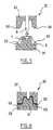
- the mold 20, shown in section transverse has a lower part 21 and an upper part 22.
- the general shape of the imprint of the mold 20 is similar to that of the mold 1 from the previous embodiment example.
- the lower part 21 of the mold 20 differs from the lower part 2 in that it has grooves 23 arranged substantially along the contour of the part to achieve.
- the upper part 22 of the mold differs from the lower part 1 in that that it has ribs 24 capable of engaging in these grooves 23 during closure mold 20.
- the drapable sheet 6 is pressed against the lower part 21 of the mold 20 using the pusher 8 mounted on the upper part 22 of the mold and movable relative to the latter, like the example of embodiment previous.
- the mold 20 is then closed, which leads to the configuration illustrated in figure 6.
- the ribs 24 cut the sheet 6 along a predetermined contour in coming to engage in the gorges 23.
- Figure 7 shows in perspective and schematically a part 30 obtained with the mold 20 which has just been described.
- the part 30 constitutes in the example described a bumper beam for motor vehicle.
- This hollow 31 corresponds to the recess 7.
- the surround 33 of the part 30 is connected to the latter only by means of bridges of material 34 extending between the cutouts 32, easy to cut.
- Bezel 10 can be used to form a compression chamber 40 with the upper 3 and lower 2 parts of the mold, as will be described in reference to figure 8.
- an interval between the upper parts 3 and bottom 2 of the mold above the ply 6 and the interior surface 10 is positioned of the bezel 19 at this interval, to close it.
- An injection channel for pressurized thermoplastic material allows a certain amount 41 of thermoplastic material to be injected into the mold in contact with the ply 6, in the abovementioned interval, in order to produce ribs of stiffening for example.
- the mold does not have an injection channel and the material thermoplastic is deposited in the mold by extrusion before it is closed.
- the drapable tablecloth 6 is constituted by a tablecloth of TWINTEX.
- FIG 9 a mold 1 'different from mold 1 by the fact that it includes additional peripheral pushers 8 'arranged on either side of the central pusher 8.
Landscapes
- Engineering & Computer Science (AREA)
- Mechanical Engineering (AREA)
- Chemical & Material Sciences (AREA)
- Composite Materials (AREA)
- Casting Or Compression Moulding Of Plastics Or The Like (AREA)
- Blow-Moulding Or Thermoforming Of Plastics Or The Like (AREA)
- Moulds For Moulding Plastics Or The Like (AREA)
Applications Claiming Priority (3)
| Application Number | Priority Date | Filing Date | Title |
|---|---|---|---|
| FR3500030 | 2000-03-20 | ||
| FR0003530 | 2000-03-20 | ||
| FR0003530A FR2806349B1 (fr) | 2000-03-20 | 2000-03-20 | Procede de fabrication d'une piece en matiere plastique renforcee |
Publications (3)
| Publication Number | Publication Date |
|---|---|
| EP1136239A2 true EP1136239A2 (de) | 2001-09-26 |
| EP1136239A3 EP1136239A3 (de) | 2002-09-11 |
| EP1136239B1 EP1136239B1 (de) | 2005-10-26 |
Family
ID=8848283
Family Applications (1)
| Application Number | Title | Priority Date | Filing Date |
|---|---|---|---|
| EP01400703A Expired - Lifetime EP1136239B1 (de) | 2000-03-20 | 2001-03-16 | Verfahren zur Herstellung eines verstärkten thermoplastischen Werkstücks und Form |
Country Status (5)
| Country | Link |
|---|---|
| US (1) | US6749784B2 (de) |
| EP (1) | EP1136239B1 (de) |
| DE (1) | DE60114275T2 (de) |
| ES (1) | ES2248250T3 (de) |
| FR (1) | FR2806349B1 (de) |
Cited By (12)
| Publication number | Priority date | Publication date | Assignee | Title |
|---|---|---|---|---|
| EP1495892A1 (de) * | 2003-07-07 | 2005-01-12 | Webasto AG | Öffnungsfähiges Panoramadach für ein Fahrzeug |
| US7622066B2 (en) | 2004-07-26 | 2009-11-24 | The Boeing Company | Methods and systems for manufacturing composite parts with female tools |
| US7951318B2 (en) | 2004-09-29 | 2011-05-31 | The Boeing Company | Apparatuses, systems, and methods for manufacturing composite parts |
| US8465613B2 (en) | 2011-08-24 | 2013-06-18 | The Boeing Company | Method and apparatus for fabricating variable gauge, contoured composite stiffeners |
| US8557165B2 (en) | 2008-10-25 | 2013-10-15 | The Boeing Company | Forming highly contoured composite parts |
| US8601694B2 (en) | 2008-06-13 | 2013-12-10 | The Boeing Company | Method for forming and installing stringers |
| US8632330B2 (en) | 2006-01-31 | 2014-01-21 | The Boeing Company | Tools for manufacturing composite parts and methods for using such tools |
| US9254619B2 (en) | 2008-05-28 | 2016-02-09 | The Boeing Company | Method and apparatus for fabricating variable gauge, contoured composite stiffeners |
| US9387628B2 (en) | 2011-08-24 | 2016-07-12 | The Boeing Company | Method and apparatus for fabricating composite stringers |
| EP3059063A4 (de) * | 2013-10-17 | 2016-10-12 | Toyota Motor Co Ltd | Verfahren zum formen eines thermoplastischen kunststoffmaterials |
| WO2018073324A1 (fr) * | 2016-10-19 | 2018-04-26 | Roctool | Procédé et dispositif pour la consolidation d'une préforme textile et surmoulage |
| US10369740B2 (en) | 2015-07-09 | 2019-08-06 | The Boeing Company | Method of forming a contoured hat stiffener |
Families Citing this family (24)
| Publication number | Priority date | Publication date | Assignee | Title |
|---|---|---|---|---|
| US20040191373A1 (en) * | 2003-01-21 | 2004-09-30 | Leonard Paul | Pan spray formulation and delivery system |
| US9028633B1 (en) * | 2003-06-27 | 2015-05-12 | Avtec Industries, Inc. | Fire and smoke suppressing surface for substrates |
| CN100574920C (zh) * | 2003-08-28 | 2009-12-30 | 有限公司里那西美特利 | 液压成形装置以及液压成形方法 |
| EP1559533B1 (de) * | 2004-01-28 | 2010-06-02 | Lightweight Structures B.V. | Verfahren zur Herstellung von Vorformlingen aus faserigem Schichtmaterial |
| WO2006091245A2 (en) * | 2004-10-22 | 2006-08-31 | Dow Global Technologies Inc. | Plastic composite articles and methods of making same |
| JP5117413B2 (ja) * | 2006-03-08 | 2013-01-16 | レクティセル アウトモービルジステメ ゲゼルシャフト ミット ベシュレンクテル ハフツング | 三次元形状サンドイッチ構造を製作するための方法 |
| US7625036B2 (en) * | 2006-04-04 | 2009-12-01 | Oakwood Energy Management, Inc. | Multi-sectional modular energy absorber and method for configuring same |
| GB0614087D0 (en) | 2006-07-14 | 2006-08-23 | Airbus Uk Ltd | Composite manufacturing method |
| US8388795B2 (en) | 2007-05-17 | 2013-03-05 | The Boeing Company | Nanotube-enhanced interlayers for composite structures |
| US8042767B2 (en) | 2007-09-04 | 2011-10-25 | The Boeing Company | Composite fabric with rigid member structure |
| CN101537691B (zh) * | 2008-03-19 | 2012-09-19 | 深圳富泰宏精密工业有限公司 | 注塑模具及应用其制造壳体的方法 |
| DE102011012499B4 (de) * | 2011-02-25 | 2016-06-16 | Benteler Sgl Gmbh & Co. Kg | Vorrichtung und Verfahren zum Herstellen eines Faserverbundwerkstückes |
| DE102011012500B4 (de) * | 2011-02-25 | 2014-05-15 | Benteler Sgl Gmbh & Co. Kg | Vorrichtung und Verfahren zum Herstellen eines Faserverbundwerkstückes |
| DE102012202620B4 (de) | 2011-11-17 | 2015-02-26 | Johnson Controls Gmbh | Verfahren zur Herstellung eines Strukturbauteils, Vorrichtung zur Durchführung des Verfahrens |
| GB201120219D0 (en) | 2011-11-23 | 2012-01-04 | Airbus Operations Ltd | Wrinkle control method and tool therefor |
| DE102012006038A1 (de) * | 2012-03-27 | 2013-10-02 | Mbb Fertigungstechnik Gmbh | Umformwerkzeug zur Herstellung eines im Wesentlichen schalenförmigen, faserverstärkten Kunststoffteils |
| DE102012210114A1 (de) * | 2012-06-15 | 2013-12-19 | Johnson Controls Gmbh | Verfahren und Vorrichtung zur Umformung eines Organoblechs |
| US9415708B2 (en) | 2014-02-18 | 2016-08-16 | Oakwood Energy Management, Inc. | Conformable energy absorber |
| JP6137056B2 (ja) * | 2014-06-04 | 2017-05-31 | トヨタ自動車株式会社 | 自動車用樹脂部品の製造方法及び自動車用樹脂部品の製造装置 |
| DE102014222243A1 (de) * | 2014-10-31 | 2016-05-04 | Bayerische Motoren Werke Aktiengesellschaft | Verfahren zum Verarbeiten eines unidirektionalen Fasergeleges in einem Presswerkzeug sowie Presswerkzeug hierfür |
| EP3401072B1 (de) * | 2016-01-08 | 2020-04-29 | Teijin Limited | Verfahren zur herstellung eines faserverstärkten harzformkörpers |
| DE102016116418A1 (de) * | 2016-09-02 | 2018-03-08 | Dieffenbacher GmbH Maschinen- und Anlagenbau | Verfahren und Drapiervorrichtung zur Herstellung eines dreidimensionalen Vorformlings |
| JP7052571B2 (ja) * | 2018-06-04 | 2022-04-12 | トヨタ自動車株式会社 | 成形装置および成形品の製造方法 |
| US12128639B2 (en) * | 2020-07-31 | 2024-10-29 | Mitsubishi Heavy Industries, Ltd. | Forming device and forming method |
Family Cites Families (20)
| Publication number | Priority date | Publication date | Assignee | Title |
|---|---|---|---|---|
| US2484656A (en) * | 1945-07-09 | 1949-10-11 | Basheshar N Sikka | Apparatus for molding plastic sheet material |
| US3115678A (en) * | 1960-10-07 | 1963-12-31 | Collins & Aikman Corp | Apparatus for molding plastic carpets |
| US3337664A (en) * | 1965-05-05 | 1967-08-22 | Illinois Tool Works | Method and apparatus for forming thermoplastic articles of unusual configuration |
| SE7905318L (sv) * | 1978-06-28 | 1979-12-29 | Gor Applic Speciali Srl | Forfarande och anordning for framstellning av kascherade formdelar |
| AU532845B2 (en) * | 1979-11-20 | 1983-10-13 | Albert Fradin | Moulding slow setting material |
| US4545105A (en) * | 1981-10-13 | 1985-10-08 | Autodynamics Corporation Of America | Method of making bright-faced reinforced plastic bumper |
| JPH0757522B2 (ja) * | 1987-11-30 | 1995-06-21 | 凸版印刷株式会社 | プラスチックシートの熱成形方法及びそれに用いる型 |
| GB8801599D0 (en) * | 1988-01-25 | 1988-02-24 | Du Pont Canada | Process for injection moulding of multi-layered articles |
| JPH01235613A (ja) * | 1988-03-16 | 1989-09-20 | Sumitomo Chem Co Ltd | 多層成形品の製造方法 |
| US4961700A (en) * | 1988-12-15 | 1990-10-09 | Owens-Corning Fiberglas Corporation | Shaping means for the production of fiber-reinforced preform articles |
| US4909721A (en) * | 1989-02-16 | 1990-03-20 | Mobil Oil Corporation | Mold apparatus for molding containers and forming hole therein |
| IT1230255B (it) * | 1989-06-09 | 1991-10-18 | Dante Siano | Procedimento e stampo per pannelli rivestiti. |
| US5085571A (en) * | 1989-12-11 | 1992-02-04 | Dolco Packaging Corporation | Mold containing an adjustable key |
| US5040962A (en) * | 1989-12-12 | 1991-08-20 | The Dow Chemical Company | Reaction injection molding apparatus with internal frame and shear edge |
| US5032106A (en) * | 1989-12-18 | 1991-07-16 | Mobil Oil Corporation | Mold apparatus for forming an orifice in a structure during molding thereof |
| US5114651A (en) * | 1989-12-18 | 1992-05-19 | Mobil Oil Corporation | Method of forming an orifice in a structure during molding thereof |
| JPH05154868A (ja) * | 1991-12-10 | 1993-06-22 | Dainippon Printing Co Ltd | 容器成形装置 |
| US6159402A (en) * | 1992-08-04 | 2000-12-12 | Valyi; Emery I. | Process for forming a color coated article |
| US5800759A (en) * | 1992-12-27 | 1998-09-01 | Nissha Printing Co., Ltd. | Insert molded article, and apparatus and method for producing the insert molded article |
| US6132669A (en) * | 1997-08-14 | 2000-10-17 | The Elizabeth And Sandor Valyi Foundation, Inc. | Process for preparing a molded article |
-
2000
- 2000-03-20 FR FR0003530A patent/FR2806349B1/fr not_active Expired - Fee Related
-
2001
- 2001-03-16 EP EP01400703A patent/EP1136239B1/de not_active Expired - Lifetime
- 2001-03-16 DE DE60114275T patent/DE60114275T2/de not_active Expired - Lifetime
- 2001-03-16 ES ES01400703T patent/ES2248250T3/es not_active Expired - Lifetime
- 2001-03-20 US US09/811,617 patent/US6749784B2/en not_active Expired - Fee Related
Cited By (19)
| Publication number | Priority date | Publication date | Assignee | Title |
|---|---|---|---|---|
| EP1495892A1 (de) * | 2003-07-07 | 2005-01-12 | Webasto AG | Öffnungsfähiges Panoramadach für ein Fahrzeug |
| US7622066B2 (en) | 2004-07-26 | 2009-11-24 | The Boeing Company | Methods and systems for manufacturing composite parts with female tools |
| US8974212B2 (en) | 2004-07-26 | 2015-03-10 | The Boeing Company | Systems for manufacturing composite parts with female tools |
| US7951318B2 (en) | 2004-09-29 | 2011-05-31 | The Boeing Company | Apparatuses, systems, and methods for manufacturing composite parts |
| US9561602B2 (en) | 2005-04-13 | 2017-02-07 | The Boeing Company | Forming highly contoured composite parts |
| US9162380B2 (en) | 2005-04-13 | 2015-10-20 | The Boeing Company | Forming highly contoured composite parts |
| US8632330B2 (en) | 2006-01-31 | 2014-01-21 | The Boeing Company | Tools for manufacturing composite parts and methods for using such tools |
| US9254619B2 (en) | 2008-05-28 | 2016-02-09 | The Boeing Company | Method and apparatus for fabricating variable gauge, contoured composite stiffeners |
| US9387627B2 (en) | 2008-06-13 | 2016-07-12 | The Boeing Company | Apparatus for forming and installing stringers |
| US8601694B2 (en) | 2008-06-13 | 2013-12-10 | The Boeing Company | Method for forming and installing stringers |
| US8557165B2 (en) | 2008-10-25 | 2013-10-15 | The Boeing Company | Forming highly contoured composite parts |
| US9387628B2 (en) | 2011-08-24 | 2016-07-12 | The Boeing Company | Method and apparatus for fabricating composite stringers |
| US8465613B2 (en) | 2011-08-24 | 2013-06-18 | The Boeing Company | Method and apparatus for fabricating variable gauge, contoured composite stiffeners |
| EP3059063A4 (de) * | 2013-10-17 | 2016-10-12 | Toyota Motor Co Ltd | Verfahren zum formen eines thermoplastischen kunststoffmaterials |
| US10569463B2 (en) | 2013-10-17 | 2020-02-25 | Toyota Jidosha Kabushiki Kaisha | Method of molding thermoplastic resin material |
| US10369740B2 (en) | 2015-07-09 | 2019-08-06 | The Boeing Company | Method of forming a contoured hat stiffener |
| US11370159B2 (en) | 2015-07-09 | 2022-06-28 | The Boeing Company | Apparatus for forming a contoured hat stiffener |
| WO2018073324A1 (fr) * | 2016-10-19 | 2018-04-26 | Roctool | Procédé et dispositif pour la consolidation d'une préforme textile et surmoulage |
| US11390001B2 (en) | 2016-10-19 | 2022-07-19 | Roctool | Method and device for consolidating a textile preform and overmoulding |
Also Published As
| Publication number | Publication date |
|---|---|
| ES2248250T3 (es) | 2006-03-16 |
| DE60114275T2 (de) | 2006-07-27 |
| DE60114275D1 (de) | 2005-12-01 |
| EP1136239B1 (de) | 2005-10-26 |
| US20010045684A1 (en) | 2001-11-29 |
| FR2806349B1 (fr) | 2002-12-06 |
| FR2806349A1 (fr) | 2001-09-21 |
| EP1136239A3 (de) | 2002-09-11 |
| US6749784B2 (en) | 2004-06-15 |
Similar Documents
| Publication | Publication Date | Title |
|---|---|---|
| EP1136239B1 (de) | Verfahren zur Herstellung eines verstärkten thermoplastischen Werkstücks und Form | |
| EP1778451B1 (de) | Form zum spritzgiessen eines kunststoffteils und gussverfahren | |
| EP3178631B1 (de) | Formvorrichtung zum warmformen durch ansaugen, produktionsverfahren, bei der sie zum einsatz kommt und hergestellter gegenstand | |
| EP1103362B1 (de) | Formwerkzeug zum Formen einer Reifenlauffläche | |
| FR2572676A1 (fr) | Procede et appareil de faconnage de moulages en resine synthetique multicolores | |
| FR2651171A1 (fr) | Procede et dispositif de fabrication de moulure de cote de caisse de vehicule a partir de matiere thermoplastique extrudee, par refaconnage par compression a chaud dans un moule et bande obtenue. | |
| EP0722816B1 (de) | Verfahren und Vorrichtung zur Herstellung zumindest eines Teils einer Reifenform mit zumindest einem Formteil zur Formgebung eines nichtentformbaren Musters | |
| FR2717116A1 (fr) | Pièce moulée en matière plastique doublée d'une feuille, ainsi que procédé et dispositif pour sa fabrication. | |
| EP1123788B1 (de) | Formwerkzeug mit bewegbarer Trennebene zur Herstellung von Kunststoffteilen sowie Verfahren zur Verwendung eines solchen Formwerkzeugs | |
| EP0636464A1 (de) | Verfahren zum begrenzten Einfügen eines Dekors in einem thermoplastischen Substrat | |
| EP1136237B1 (de) | Faserverstärktes Kunststoffteil und Verfahren zur Herstellung | |
| EP2955000B1 (de) | Formvorrichtung zum warmformen, und produktionsverfahren, bei der sie zum einsatz kommt | |
| EP3636410B1 (de) | Herstellungsverfahren eines aufformteils, das ein strukturteil eines fahrzeugs bildet | |
| EP0806274B1 (de) | Verfahren zur Verkleidung eines Kunststoffteiles mit einer während des Verfahrens geschnittenen Folie und hergestellter Teil | |
| EP0724942A1 (de) | Verfahren und Formen zur Herstellung von Kunststoff-Verbundgegenständen mit einer Oberflächenschicht und dadurch hergestellte Gegenstände | |
| EP0895846B1 (de) | Verfahren und Form zum Herstellen eines bekleideten Kunstoffgegenstandes mit einer geschnittenen und entspannten Dekorfolie. | |
| EP0707533B1 (de) | Verfahren zur herstellung eines mehrschichtigen gegenstandes durch giessen und form zur herstellung eines solchen gegenstandes | |
| FR2768360A1 (fr) | Procede de moulage d'une piece avec contre-depouille, moule utilise et piece obtenue | |
| EP1838515B1 (de) | Vorrichtung zum thermoformen von objekten mit basisflansch | |
| FR3038248A1 (fr) | Procede et dispositif pour la fabrication d'une piece hybride ou composite a base de materiau thermoplastique presentant une face d'aspect et une face technique | |
| EP1095840B1 (de) | Kraftfahrzeuglenkrad und Verfahren zu seiner Herstellung | |
| FR2878182A1 (fr) | Procede et dispositif pour la decoupe des seuils d'injection issus d'une operation de moulage d'une piece par injection d'une matiere thermoplastique | |
| FR2841818A1 (fr) | Procede, moule et dispositif de fabrication d'une piece perforee moulee en matiere composite | |
| FR2705247A1 (fr) | Procédé pour fabriquer un ski en forme. | |
| FR3124756A1 (fr) | Procédé de fabrication d’un élément de garnissage à double décor et dispositif associé |
Legal Events
| Date | Code | Title | Description |
|---|---|---|---|
| PUAI | Public reference made under article 153(3) epc to a published international application that has entered the european phase |
Free format text: ORIGINAL CODE: 0009012 |
|
| AK | Designated contracting states |
Kind code of ref document: A2 Designated state(s): AT BE CH CY DE DK ES FI FR GB GR IE IT LI LU MC NL PT SE TR |
|
| AX | Request for extension of the european patent |
Free format text: AL;LT;LV;MK;RO;SI |
|
| PUAL | Search report despatched |
Free format text: ORIGINAL CODE: 0009013 |
|
| AK | Designated contracting states |
Kind code of ref document: A3 Designated state(s): AT BE CH CY DE DK ES FI FR GB GR IE IT LI LU MC NL PT SE TR |
|
| AX | Request for extension of the european patent |
Free format text: AL;LT;LV;MK;RO;SI |
|
| RIC1 | Information provided on ipc code assigned before grant |
Free format text: 7B 29C 70/46 A, 7B 29C 51/08 B, 7B 29C 51/32 B |
|
| 17P | Request for examination filed |
Effective date: 20021118 |
|
| AKX | Designation fees paid |
Designated state(s): DE ES FR GB IT |
|
| 17Q | First examination report despatched |
Effective date: 20040218 |
|
| RTI1 | Title (correction) |
Free format text: METHOD FOR PRODUCING A REINFORCED THERMOPLASTIC PART AND MOULD |
|
| GRAP | Despatch of communication of intention to grant a patent |
Free format text: ORIGINAL CODE: EPIDOSNIGR1 |
|
| GRAS | Grant fee paid |
Free format text: ORIGINAL CODE: EPIDOSNIGR3 |
|
| GRAA | (expected) grant |
Free format text: ORIGINAL CODE: 0009210 |
|
| AK | Designated contracting states |
Kind code of ref document: B1 Designated state(s): DE ES FR GB IT |
|
| REG | Reference to a national code |
Ref country code: GB Ref legal event code: FG4D Free format text: NOT ENGLISH |
|
| GBT | Gb: translation of ep patent filed (gb section 77(6)(a)/1977) |
Effective date: 20051026 |
|
| REF | Corresponds to: |
Ref document number: 60114275 Country of ref document: DE Date of ref document: 20051201 Kind code of ref document: P |
|
| REG | Reference to a national code |
Ref country code: ES Ref legal event code: FG2A Ref document number: 2248250 Country of ref document: ES Kind code of ref document: T3 |
|
| PLBE | No opposition filed within time limit |
Free format text: ORIGINAL CODE: 0009261 |
|
| STAA | Information on the status of an ep patent application or granted ep patent |
Free format text: STATUS: NO OPPOSITION FILED WITHIN TIME LIMIT |
|
| 26N | No opposition filed |
Effective date: 20060727 |
|
| PGFP | Annual fee paid to national office [announced via postgrant information from national office to epo] |
Ref country code: IT Payment date: 20140331 Year of fee payment: 14 Ref country code: ES Payment date: 20140428 Year of fee payment: 14 |
|
| PG25 | Lapsed in a contracting state [announced via postgrant information from national office to epo] |
Ref country code: IT Free format text: LAPSE BECAUSE OF NON-PAYMENT OF DUE FEES Effective date: 20150316 |
|
| REG | Reference to a national code |
Ref country code: FR Ref legal event code: PLFP Year of fee payment: 16 |
|
| REG | Reference to a national code |
Ref country code: ES Ref legal event code: FD2A Effective date: 20160428 |
|
| PG25 | Lapsed in a contracting state [announced via postgrant information from national office to epo] |
Ref country code: ES Free format text: LAPSE BECAUSE OF NON-PAYMENT OF DUE FEES Effective date: 20150317 |
|
| REG | Reference to a national code |
Ref country code: FR Ref legal event code: PLFP Year of fee payment: 17 |
|
| PGFP | Annual fee paid to national office [announced via postgrant information from national office to epo] |
Ref country code: DE Payment date: 20170322 Year of fee payment: 17 |
|
| PGFP | Annual fee paid to national office [announced via postgrant information from national office to epo] |
Ref country code: GB Payment date: 20170322 Year of fee payment: 17 |
|
| REG | Reference to a national code |
Ref country code: FR Ref legal event code: PLFP Year of fee payment: 18 |
|
| PGFP | Annual fee paid to national office [announced via postgrant information from national office to epo] |
Ref country code: FR Payment date: 20180208 Year of fee payment: 18 |
|
| REG | Reference to a national code |
Ref country code: DE Ref legal event code: R119 Ref document number: 60114275 Country of ref document: DE |
|
| GBPC | Gb: european patent ceased through non-payment of renewal fee |
Effective date: 20180316 |
|
| PG25 | Lapsed in a contracting state [announced via postgrant information from national office to epo] |
Ref country code: DE Free format text: LAPSE BECAUSE OF NON-PAYMENT OF DUE FEES Effective date: 20181002 |
|
| PG25 | Lapsed in a contracting state [announced via postgrant information from national office to epo] |
Ref country code: GB Free format text: LAPSE BECAUSE OF NON-PAYMENT OF DUE FEES Effective date: 20180316 |
|
| PG25 | Lapsed in a contracting state [announced via postgrant information from national office to epo] |
Ref country code: FR Free format text: LAPSE BECAUSE OF NON-PAYMENT OF DUE FEES Effective date: 20190331 |