EP1136243B1 - Verfahren zur Herstellung von Luftreifen - Google Patents
Verfahren zur Herstellung von Luftreifen Download PDFInfo
- Publication number
- EP1136243B1 EP1136243B1 EP01302410A EP01302410A EP1136243B1 EP 1136243 B1 EP1136243 B1 EP 1136243B1 EP 01302410 A EP01302410 A EP 01302410A EP 01302410 A EP01302410 A EP 01302410A EP 1136243 B1 EP1136243 B1 EP 1136243B1
- Authority
- EP
- European Patent Office
- Prior art keywords
- cylindrical body
- drum
- edge portions
- building drum
- pressing
- Prior art date
- Legal status (The legal status is an assumption and is not a legal conclusion. Google has not performed a legal analysis and makes no representation as to the accuracy of the status listed.)
- Expired - Lifetime
Links
- 238000004519 manufacturing process Methods 0.000 title claims description 8
- 239000011324 bead Substances 0.000 claims description 32
- 238000003825 pressing Methods 0.000 claims description 16
- 229920001971 elastomer Polymers 0.000 claims description 11
- 230000003247 decreasing effect Effects 0.000 claims description 9
- 238000000034 method Methods 0.000 claims description 9
- 230000008961 swelling Effects 0.000 claims description 4
- 238000004804 winding Methods 0.000 claims description 4
- 239000000463 material Substances 0.000 description 6
- 238000010586 diagram Methods 0.000 description 4
- 230000003014 reinforcing effect Effects 0.000 description 4
- 230000006866 deterioration Effects 0.000 description 2
- 230000001419 dependent effect Effects 0.000 description 1
- 239000000806 elastomer Substances 0.000 description 1
- 230000002265 prevention Effects 0.000 description 1
- 238000010998 test method Methods 0.000 description 1
Images




Classifications
-
- B—PERFORMING OPERATIONS; TRANSPORTING
- B29—WORKING OF PLASTICS; WORKING OF SUBSTANCES IN A PLASTIC STATE IN GENERAL
- B29D—PRODUCING PARTICULAR ARTICLES FROM PLASTICS OR FROM SUBSTANCES IN A PLASTIC STATE
- B29D30/00—Producing pneumatic or solid tyres or parts thereof
- B29D30/06—Pneumatic tyres or parts thereof (e.g. produced by casting, moulding, compression moulding, injection moulding, centrifugal casting)
- B29D30/08—Building tyres
- B29D30/20—Building tyres by the flat-tyre method, i.e. building on cylindrical drums
-
- B—PERFORMING OPERATIONS; TRANSPORTING
- B29—WORKING OF PLASTICS; WORKING OF SUBSTANCES IN A PLASTIC STATE IN GENERAL
- B29D—PRODUCING PARTICULAR ARTICLES FROM PLASTICS OR FROM SUBSTANCES IN A PLASTIC STATE
- B29D30/00—Producing pneumatic or solid tyres or parts thereof
- B29D30/06—Pneumatic tyres or parts thereof (e.g. produced by casting, moulding, compression moulding, injection moulding, centrifugal casting)
- B29D30/08—Building tyres
- B29D30/20—Building tyres by the flat-tyre method, i.e. building on cylindrical drums
- B29D30/24—Drums
- B29D30/26—Accessories or details, e.g. membranes, transfer rings
-
- B—PERFORMING OPERATIONS; TRANSPORTING
- B29—WORKING OF PLASTICS; WORKING OF SUBSTANCES IN A PLASTIC STATE IN GENERAL
- B29D—PRODUCING PARTICULAR ARTICLES FROM PLASTICS OR FROM SUBSTANCES IN A PLASTIC STATE
- B29D30/00—Producing pneumatic or solid tyres or parts thereof
- B29D30/06—Pneumatic tyres or parts thereof (e.g. produced by casting, moulding, compression moulding, injection moulding, centrifugal casting)
- B29D30/08—Building tyres
- B29D30/20—Building tyres by the flat-tyre method, i.e. building on cylindrical drums
- B29D30/32—Fitting the bead-rings or bead-cores; Folding the textile layers around the rings or cores
- B29D2030/3221—Folding over means, e.g. bladders or rigid arms
- B29D2030/3278—Folding down the ends of the tubular tyre component, e.g. the carcass, over the drum shoulders
Definitions
- the present invention relates to a method of making a green tyre being capable of improving tyre uniformity by decreasing variation of the carcass cord lengths.
- an inner liner of gas-impermeable rubber one or more strips or plies of rubberised cords for a carcass ply, reinforcing layer, etc. are wound on a building drum.
- the elastomers used in such rubber material and rubberised materials are not vulcanised when wound around the building drum. Therefore, their own adhesiveness is utilised to fix these materials onto the drum.
- the unvulcanised carcass ply material it is first wound into a substantially cylindrical shape, and then the shape is gradually changed to the finished shape or a toroidal shape.
- US Patent Number 2313035 describes a method of manufacturing a green tyre comprising the steps of:
- an object of the present invention to provide a method of making a green tyre, in which disarrangement of the carcass cords is prevented so that the carcass cords' paths are constant and thereby the deterioration in the tyre uniformity due to cord path variation is avoided.
- a method of making a green tyre which comprises the following steps:
- a building drum 1 is used to make a green tyre.
- the building drum 1 has an outer surface 1S on which unvulcanised sheet-like tyre components are wound.
- the sheet-like tyre components include at least one carcass ply and usually an inner liner rubber and optionally a reinforcing layer.
- the outer surface 1S is a cylindrically curved circumferential surface. Thus, in a cross section including the axis of the drum, the surface 1S is substantially straight and parallel with the axis.
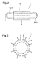
- FIG.2 An example of the building drum 1 is schematically shown in Fig.2, and it comprises a plurality of circumferentially divided sectors 4 which are arranged around the axis of the drum 1.
- the sectors 4 collectively form the above-mentioned cylindrical outer surface 1S at their radially outer positions. In order to be ab!e to contract the drum, the sectors 4 can move from the above-mentioned outer positions to inner positions.
- the building drum 1 is supported rotatably around the axis by a shaft 3.
- the tyre components (a) are wound into a cylindrical body (A) on the outer surface 1S, while rotating the building drum 1 relatively to feeders for the components.
- the winding can be done by
- case (i) firstly the inner liner rubber is wound on to the drum, and then the carcass ply is wound on the inner liner.
- case (ii) firstly the inner liner rubber and the carcass ply thereon are laminated into a sheet, and then the laminated sheet is wound on to the drum.
- case (iii) at least three sheet-like components are used, for example, an inner liner and a carcass ply which are laminated into a sheet, and another carcass ply or a reinforcing layer wound on the laminated sheet.
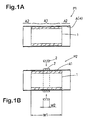
- the cylindrical body (A) is wider than the outer surface 1S, and as a result, it has a main portion A1 on the outer surface 1S and edge portions A2 which protrude from the respective edges of the outer surface 1S.
- Fig.1A shows such cylindrical body (A) formed on the building drum 1. with protruding the edge portions A2 protruding.
- the cylindrical body (A) is secured by a holding apparatus 2 so as not to allow the carcass cords therein to move axially or circumferentially of the drum.
- the holding apparatus 2 presses the main portion A1 against the outer surface 1S of the building drum 1 around the entire circumference in order to prevent the carcass cords from being moved.
- FIG.3 An example of the holding apparatus 2 is schematically shown in Fig.3, wherein a plurality of profiled presser plates 6 are arranged around the building drum 1.
- the presser plates 6 can be moved towards the axis of the building drum 1 to press the main portion A1 against the drum.
- the presser plates 6 are staggered about a circumferential line for example the centre line of the main portion A1 so as to be able to overlap each other in the pressing state thus not to form a circumferential gap between them.
- the pressing or holding width W2 by the holding apparatus 2 is preferably set in a range of not less than 0.3 times the width W1 of the main portion A1.
- the centre of the main portion A1 is preferred. In the case of two positions (not shown), near the edges of the main portion A1 are preferred. Of course, three or more positions are also possible.
- the outside diameter of the edge portions A2 is decreased by a constrictor F because the outside diameter is otherwise more than the inside diameter of the bead core C.
- the outside diameter thereof is more than the inside diameter of the bead core C, and accordingly, the outside diameter of the cylindrical body (A) wound on the drum is also more than the inside diameter of the bead core C.
- FIG.4 An example of the constrictor F is shown in Fig.4, which comprises a plurality of narrow width flat springs (f) one end of which is pivoted movably from a radial state to a parallel state.
- the longitudinal directions of the flat springs (f) are radial about the drum's axis.
- the parallel state as depicted with a solid line, the longitudinal directions are parallel to the drum's axis.
- the constrictor F in the radial state is disposed on each side of the drum coaxially therewith, and then the flat springs (f) are gradually moved towards the parallel state. Therefore, the outer surface of the edge portions A2 is compressed by the flat springs (f), and the outside diameter of the edge portions A2 becomes less than the inside diameter of the bead core C.
- the bead cores C are moved to their respective positions on the edge portions A2 from the side so that the bead cores C are located adjacently to the axial edges of the main portion A1.
- each bead core C and an unvulcanised bead apex rubber having a triangular sectional shape are assembled in advance by adhering the apex rubber onto the outer circumferential surface of the bead core C.
- each of the edge portions A2 is folded back around the bead core C and bead apex, using a folding apparatus 5. Further, as shown in Fig.1F, the main portion A1 is swelled while decreasing the width between the bead cores C, and then tread components T including a tread reinforcing belt T1, a tread rubber T2, etc. are applied to the crown portion of the expanded main portion A1. Also, rubber layers for tyre sidewall, bead and the like are applied at appropriate times.
- a green tyre is formed, and it is put in a mould and vulcanised into the finished shape.
- a bladder 5A can be used as an example of the folding apparatus 5.
- a bladder 5A is disposed on each side of the building drum 1 in its deflated sate such that a part thereof is put in the open end of the cylindrical body.
- the edge portion is contacted by the inflating bladder and folded.
- the drum 1 has to contract such that its outside diameter becomes less than the smallest inside diameters of the wound materials which occurs under the bead cores.
- the releasing of the main portion A1 from the pressing force by the holding apparatus 2 must be done after the constriction of the edge portions A2 by the constrictor F is finished.
- the releasing is done after the bead cores are set at the earliest. Also it is possible to release the main portion A1 after the edge portions A2 are folded.
- Radial tyres of size 195/65R15 for passenger cars were made experimentally according to the present invention. And the length of the carcass cord path between the bead cores was measured at eight different circumferentially spaced positions. The mean deviation and standard deviation were calculated from the data. Further, the radial force variation was measured according to JASO C607 (Test method for automobile tyre uniformity) to obtain the mean value and standard deviation of ten sample tyres.
Landscapes
- Engineering & Computer Science (AREA)
- Mechanical Engineering (AREA)
- Tyre Moulding (AREA)
- Testing Of Balance (AREA)
Claims (9)
- Verfahren zum Herstellen eines Rohreifens, das umfasst, dass eine Karkasslage aus gummierten Korden um eine Aufbautrommel (1) zu einem im Wesentlichen zylindrischen Körper (A) gewickelt wird, der zylindrische Körper (A) über den gesamten Umfang gegen die Aufbautrommel (1) gedrückt wird, Randabschnitte des im Wesentlichen zylindrischen Körpers derart verengt werden, dass ihr Außendurchmesser verringert wird, ein Wulstkern (C) um jeden der verengten Randabschnitte herum aufgesetzt wird, die Randabschnitte um die Wulstkerne (C) zurückgeschlagen werden, und ein Hauptabschnitt des zylindrischen Körpers zwischen den Wulstkernen (C) aufgebläht wird, während die Breite zwischen den Wulstkernen verringert wird, dadurch gekennzeichnet, dass
das Drücken des zylindrischen Körpers (A) gegen die Aufbautrommel (1) auf eine solche Weise ausgeführt wird, dass nicht zugelassen wird, dass die Karkasskorde sich axial und im Umfangsrichtung der Trommel bewegen, und dass der Schritt des Wegnehmens des Druckes des zylindrischen Körpers gegen die Aufbautrommel (1) frühestens ausgeführt wird, nachdem die Randabschnitte verengt worden sind. - Verfahren nach Anspruch 1, dadurch gekennzeichnet, dass die Karkasslage direkt oder indirekt auf eine im Wesentlichen zylindrische Außenfläche (1S) der Aufbautrommel (1) gewickelt wird, und dass die im Wesentlichen zylindrische Außenfläche (1S) eine schmalere axiale Breite als der im Wesentlichen zylindrische Körper (A) aufweist, und dass die zu verengenden Randabschnitte von den axialen Rändern der im Wesentlichen zylindrischen Außenfläche der Trommel abstehen.
- Verfahren nach Anspruch 1 oder 2, dadurch gekennzeichnet, dass das Drücken des zylindrischen Körpers (A) gegen die Aufbautrommel durch eine Vorrichtung vorgenommen wird, die Druckplatten (6) umfasst, die um die Aufbautrommel (1) herum angeordnet sind und in Richtung der Achse der Trommel bewegbar sind, um gegen den im Wesentlichen zylindrischen Körper (A) Druck auszuüben.
- Verfahren nach Anspruch 3, dadurch gekennzeichnet, dass die Druckplatten (6) um eine Umfangslinie herum gestaffelt sind, so dass die Druckplatten (6) einander überlappen, wenn sie auf den zylindrischen Körper (A) Druck ausüben.
- Verfahren nach einem der Ansprüche 1 bis 4, dadurch gekennzeichnet, dass das Verengen der Randabschnitte durch eine Einrichtung (F) vorgenommen wird, die eine Vielzahl von Bandfedern (f) mit geringer Breite aufweisen, von denen ein Ende aus einem radialen Zustand in einen parallelen Zustand beweglich verschwenkt wird, wobei im radialen Zustand die Längsrichtungen der Bandfedern (f) radial um die Trommelachse herum vorliegen und im parallelen Zustand die Längsrichtungen parallel zur Trommelachse vorliegen, und wobei der Randabschnitt durch die Bewegung der Bandfedern (f) aus dem radialen Zustand in den parallelen Zustand verengt wird.
- Verfahren nach einem der Ansprüche 1 bis 5, dadurch gekennzeichnet, dass das Zurückschlagen von jedem der Randabschnitte durch Aufblähen eines auf jeder Seite der Aufbautrommel (1) angeordneten Heizbalges (5A) vorgenommen wird.
- Verfahren nach einem der Ansprüche 1 bis 6, dadurch gekennzeichnet, dass das Wegnehmen des Druckes des zylindrischen Körpers (A) gegen die Aufbautrommel (1) vorgenommen wird, nachdem die Wulstkerne (C) aufgesetzt worden sind.
- Verfahren nach einem der Ansprüche 1 bis 7, dadurch gekennzeichnet, dass das Wegnehmen des Druckes des zylindrischen Körpers (A) gegen die Aufbautrommel (1) vorgenommen wird, nachdem die Randabschnitte zurückgeschlagen worden sind.
- Verfahren nach einem der Ansprüche 1 bis 8, dadurch gekennzeichnet, dass, nachdem der Hauptabschnitt des zylindrischen Körpers durch das Aufblähen auf einen bestimmten Durchmesser ausgedehnt worden ist, ein Laufstreifengummi um einen Kronenabschnitt von diesem herum angeordnet wird.
Applications Claiming Priority (2)
| Application Number | Priority Date | Filing Date | Title |
|---|---|---|---|
| JP2000076727 | 2000-03-17 | ||
| JP2000076727A JP2001260247A (ja) | 2000-03-17 | 2000-03-17 | 空気入りタイヤの製造方法 |
Publications (3)
| Publication Number | Publication Date |
|---|---|
| EP1136243A2 EP1136243A2 (de) | 2001-09-26 |
| EP1136243A3 EP1136243A3 (de) | 2002-07-24 |
| EP1136243B1 true EP1136243B1 (de) | 2005-01-12 |
Family
ID=18594421
Family Applications (1)
| Application Number | Title | Priority Date | Filing Date |
|---|---|---|---|
| EP01302410A Expired - Lifetime EP1136243B1 (de) | 2000-03-17 | 2001-03-15 | Verfahren zur Herstellung von Luftreifen |
Country Status (4)
| Country | Link |
|---|---|
| US (1) | US6511565B2 (de) |
| EP (1) | EP1136243B1 (de) |
| JP (1) | JP2001260247A (de) |
| DE (1) | DE60108283T2 (de) |
Families Citing this family (9)
| Publication number | Priority date | Publication date | Assignee | Title |
|---|---|---|---|---|
| EP1449638B1 (de) * | 2001-11-28 | 2007-04-11 | Bridgestone Corporation | Reifenherstellungsverfahren und reifenformmaschine |
| US6827119B2 (en) | 2002-03-11 | 2004-12-07 | The Goodyear Tire & Rubber Company | Radially expansible tire assembly drum and method for forming tires |
| DE10319149B4 (de) * | 2003-04-29 | 2013-05-29 | Continental Reifen Deutschland Gmbh | Verfahren zum Aufbau und Bombieren einer Reifenkarkasse sowie Anlage zur Durchführung eines solchen Verfahrens |
| EP1625931B1 (de) * | 2003-05-20 | 2008-09-24 | The Yokohama Rubber Co., Ltd. | Verfahren zur herstellung eines luftradialreifens |
| JP4462859B2 (ja) * | 2003-07-30 | 2010-05-12 | 株式会社ブリヂストン | タイヤ成型機およびタイヤの製造方法 |
| JP5690231B2 (ja) * | 2011-06-27 | 2015-03-25 | 住友ゴム工業株式会社 | カーカスプライのビードコア間のコードパスのバラツキ判定方法 |
| JP5966274B2 (ja) * | 2011-08-08 | 2016-08-10 | 横浜ゴム株式会社 | ベルト成形治具 |
| JP5425988B2 (ja) * | 2012-09-18 | 2014-02-26 | ピレリ・タイヤ・ソチエタ・ペル・アツィオーニ | タイヤを組み立てる装置 |
| JP5723412B2 (ja) * | 2013-05-20 | 2015-05-27 | 住友ゴム工業株式会社 | 自動二輪車用タイヤの製造方法 |
Family Cites Families (10)
| Publication number | Priority date | Publication date | Assignee | Title |
|---|---|---|---|---|
| US2313035A (en) * | 1939-09-22 | 1943-03-09 | Gen Tire & Rubber Co | Method of and apparatus for building tires |
| US3438832A (en) * | 1964-08-17 | 1969-04-15 | Nrm Corp | Tire building machine |
| DE1579145B1 (de) * | 1965-08-25 | 1972-02-03 | Continental Gummi Werke Ag | Maschine zum Aufbauen von Luftreifenrohlingen |
| DE1778224A1 (de) * | 1968-04-09 | 1971-08-05 | Continental Gummi Werke Ag | Reifenaufbautrommel |
| DE2134904B1 (de) * | 1971-07-13 | 1973-01-04 | Leonhard Herbert Maschinenfabrik, 6000 Bergen-Enkheim | Einrichtung zum Aufbauen und Formen eines Rohlings für Gürtelreifen |
| JPS51112885A (en) * | 1975-03-31 | 1976-10-05 | Mitsubishi Heavy Ind Ltd | Apparstus for forming breaker layer of radial tire |
| US4302274A (en) * | 1980-02-19 | 1981-11-24 | Nrm Corporation | Tire building machine |
| US4353771A (en) * | 1980-12-08 | 1982-10-12 | Nrm Corporation | Ply down assembly for tire building machine |
| JPH09131807A (ja) * | 1995-11-13 | 1997-05-20 | Bridgestone Koki Kk | タイヤ成型用ドラム |
| JP3740000B2 (ja) * | 1999-07-23 | 2006-01-25 | 三菱重工業株式会社 | タイヤ成形装置 |
-
2000
- 2000-03-17 JP JP2000076727A patent/JP2001260247A/ja active Pending
-
2001
- 2001-03-15 EP EP01302410A patent/EP1136243B1/de not_active Expired - Lifetime
- 2001-03-15 DE DE60108283T patent/DE60108283T2/de not_active Expired - Fee Related
- 2001-03-16 US US09/809,313 patent/US6511565B2/en not_active Expired - Fee Related
Also Published As
| Publication number | Publication date |
|---|---|
| US20010039993A1 (en) | 2001-11-15 |
| DE60108283D1 (de) | 2005-02-17 |
| EP1136243A3 (de) | 2002-07-24 |
| DE60108283T2 (de) | 2005-12-29 |
| EP1136243A2 (de) | 2001-09-26 |
| US6511565B2 (en) | 2003-01-28 |
| JP2001260247A (ja) | 2001-09-25 |
Similar Documents
| Publication | Publication Date | Title |
|---|---|---|
| CN1792622B (zh) | 使用高胎冠单段式轮胎成型鼓制造轮胎的方法 | |
| CN1792623B (zh) | 高胎冠单段式轮胎成型鼓 | |
| EP1504883B1 (de) | Eine einen hohen Scheitel aufweisende Aufbautrommel zur Herstellung einer erststufigen Karkasse | |
| US6769468B2 (en) | Tire building drum having expandable center section and independently expandable bead lock assemblies in the end sections | |
| CN100377865C (zh) | 轮胎制造方法以及生胎制造装置 | |
| US7931768B2 (en) | Method and device for constructing a radial tire | |
| US20080283166A1 (en) | Method for manufacturing pneumatic tire | |
| KR20020087085A (ko) | 턴업 장치가 마련되어 있는 타이어 성형용 드럼 | |
| US11001022B2 (en) | Method for manufacturing motorcycle tire | |
| CN104553008A (zh) | 单阶段轮胎成型鼓 | |
| EP1136243B1 (de) | Verfahren zur Herstellung von Luftreifen | |
| CA1069423A (en) | Method and apparatus for building a closed torus tire | |
| EP0468738A2 (de) | Verfahren und Gürtelbildungstrommel zum Aufbau eines Rohreifens | |
| KR20110061543A (ko) | 차륜용 타이어를 제조하는 공정 및 장치 | |
| JP4173711B2 (ja) | ランフラットタイヤの製造方法 | |
| EP1323517B1 (de) | Verfahren zur Reifenherstellung | |
| EP0302935B1 (de) | Radialreifen für flugzeug und dessen herstellung | |
| JPH03118144A (ja) | 空気入りタイヤとその製造方法 | |
| JP5116011B2 (ja) | タイヤ製造装置及び製造方法 | |
| JPH0647274B2 (ja) | 航空機用ラジアルタイヤの製造方法 | |
| RU2311295C2 (ru) | Способ и устройство для изготовления пневматической шины для колес транспортных средств | |
| JP2001252991A (ja) | 空気入りタイヤの製造方法 | |
| JP2001113611A (ja) | 空気入りタイヤの製造方法 |
Legal Events
| Date | Code | Title | Description |
|---|---|---|---|
| PUAI | Public reference made under article 153(3) epc to a published international application that has entered the european phase |
Free format text: ORIGINAL CODE: 0009012 |
|
| AK | Designated contracting states |
Kind code of ref document: A2 Designated state(s): AT BE CH CY DE DK ES FI FR GB GR IE IT LI LU MC NL PT SE TR |
|
| AX | Request for extension of the european patent |
Free format text: AL;LT;LV;MK;RO;SI |
|
| PUAL | Search report despatched |
Free format text: ORIGINAL CODE: 0009013 |
|
| AK | Designated contracting states |
Kind code of ref document: A3 Designated state(s): AT BE CH CY DE DK ES FI FR GB GR IE IT LI LU MC NL PT SE TR |
|
| AX | Request for extension of the european patent |
Free format text: AL;LT;LV;MK;RO;SI |
|
| 17P | Request for examination filed |
Effective date: 20021015 |
|
| AKX | Designation fees paid |
Designated state(s): DE FR GB IT |
|
| 17Q | First examination report despatched |
Effective date: 20030825 |
|
| GRAP | Despatch of communication of intention to grant a patent |
Free format text: ORIGINAL CODE: EPIDOSNIGR1 |
|
| GRAS | Grant fee paid |
Free format text: ORIGINAL CODE: EPIDOSNIGR3 |
|
| GRAA | (expected) grant |
Free format text: ORIGINAL CODE: 0009210 |
|
| AK | Designated contracting states |
Kind code of ref document: B1 Designated state(s): DE FR GB IT |
|
| REG | Reference to a national code |
Ref country code: GB Ref legal event code: FG4D |
|
| REF | Corresponds to: |
Ref document number: 60108283 Country of ref document: DE Date of ref document: 20050217 Kind code of ref document: P |
|
| REG | Reference to a national code |
Ref country code: IE Ref legal event code: FG4D |
|
| PLBE | No opposition filed within time limit |
Free format text: ORIGINAL CODE: 0009261 |
|
| STAA | Information on the status of an ep patent application or granted ep patent |
Free format text: STATUS: NO OPPOSITION FILED WITHIN TIME LIMIT |
|
| ET | Fr: translation filed | ||
| 26N | No opposition filed |
Effective date: 20051013 |
|
| PGFP | Annual fee paid to national office [announced via postgrant information from national office to epo] |
Ref country code: IT Payment date: 20060331 Year of fee payment: 6 |
|
| PGFP | Annual fee paid to national office [announced via postgrant information from national office to epo] |
Ref country code: DE Payment date: 20070308 Year of fee payment: 7 |
|
| PGFP | Annual fee paid to national office [announced via postgrant information from national office to epo] |
Ref country code: GB Payment date: 20070314 Year of fee payment: 7 |
|
| PGFP | Annual fee paid to national office [announced via postgrant information from national office to epo] |
Ref country code: FR Payment date: 20070308 Year of fee payment: 7 |
|
| GBPC | Gb: european patent ceased through non-payment of renewal fee |
Effective date: 20080315 |
|
| REG | Reference to a national code |
Ref country code: FR Ref legal event code: ST Effective date: 20081125 |
|
| PG25 | Lapsed in a contracting state [announced via postgrant information from national office to epo] |
Ref country code: DE Free format text: LAPSE BECAUSE OF NON-PAYMENT OF DUE FEES Effective date: 20081001 |
|
| PG25 | Lapsed in a contracting state [announced via postgrant information from national office to epo] |
Ref country code: FR Free format text: LAPSE BECAUSE OF NON-PAYMENT OF DUE FEES Effective date: 20080331 |
|
| PG25 | Lapsed in a contracting state [announced via postgrant information from national office to epo] |
Ref country code: GB Free format text: LAPSE BECAUSE OF NON-PAYMENT OF DUE FEES Effective date: 20080315 |
|
| PG25 | Lapsed in a contracting state [announced via postgrant information from national office to epo] |
Ref country code: IT Free format text: LAPSE BECAUSE OF NON-PAYMENT OF DUE FEES Effective date: 20070315 |