EP1136249A1 - Zylindrische Papiertrommel und Herstellungsverfahren dafür - Google Patents
Zylindrische Papiertrommel und Herstellungsverfahren dafür Download PDFInfo
- Publication number
- EP1136249A1 EP1136249A1 EP20010302044 EP01302044A EP1136249A1 EP 1136249 A1 EP1136249 A1 EP 1136249A1 EP 20010302044 EP20010302044 EP 20010302044 EP 01302044 A EP01302044 A EP 01302044A EP 1136249 A1 EP1136249 A1 EP 1136249A1
- Authority
- EP
- European Patent Office
- Prior art keywords
- roll
- curled
- cylindrical body
- opening
- paper
- Prior art date
- Legal status (The legal status is an assumption and is not a legal conclusion. Google has not performed a legal analysis and makes no representation as to the accuracy of the status listed.)
- Granted
Links
- 238000004519 manufacturing process Methods 0.000 title abstract description 6
- 230000001681 protective effect Effects 0.000 claims abstract description 39
- 239000000463 material Substances 0.000 claims abstract description 32
- 239000000853 adhesive Substances 0.000 claims abstract description 21
- 230000001070 adhesive effect Effects 0.000 claims abstract description 21
- 239000000835 fiber Substances 0.000 claims abstract description 13
- 238000004804 winding Methods 0.000 claims abstract description 3
- 239000000123 paper Substances 0.000 description 31
- 239000010410 layer Substances 0.000 description 12
- 238000003825 pressing Methods 0.000 description 7
- 238000000034 method Methods 0.000 description 4
- 208000027418 Wounds and injury Diseases 0.000 description 3
- 239000011248 coating agent Substances 0.000 description 3
- 238000000576 coating method Methods 0.000 description 3
- 230000006378 damage Effects 0.000 description 3
- 208000014674 injury Diseases 0.000 description 3
- 229920003002 synthetic resin Polymers 0.000 description 3
- 239000000057 synthetic resin Substances 0.000 description 3
- 239000008187 granular material Substances 0.000 description 2
- 239000011796 hollow space material Substances 0.000 description 2
- 238000002844 melting Methods 0.000 description 2
- 230000008018 melting Effects 0.000 description 2
- 239000002184 metal Substances 0.000 description 2
- 239000000843 powder Substances 0.000 description 2
- 238000004064 recycling Methods 0.000 description 2
- 230000002787 reinforcement Effects 0.000 description 2
- 238000000926 separation method Methods 0.000 description 2
- 229920000298 Cellophane Polymers 0.000 description 1
- 239000004743 Polypropylene Substances 0.000 description 1
- 239000004372 Polyvinyl alcohol Substances 0.000 description 1
- 239000012790 adhesive layer Substances 0.000 description 1
- 230000015572 biosynthetic process Effects 0.000 description 1
- 238000011109 contamination Methods 0.000 description 1
- 238000005336 cracking Methods 0.000 description 1
- 230000007423 decrease Effects 0.000 description 1
- 230000000694 effects Effects 0.000 description 1
- 239000000839 emulsion Substances 0.000 description 1
- 239000012847 fine chemical Substances 0.000 description 1
- 230000002401 inhibitory effect Effects 0.000 description 1
- 239000000314 lubricant Substances 0.000 description 1
- 229940127554 medical product Drugs 0.000 description 1
- 239000011087 paperboard Substances 0.000 description 1
- 229940075065 polyvinyl acetate Drugs 0.000 description 1
- 239000011118 polyvinyl acetate Substances 0.000 description 1
- 229920002451 polyvinyl alcohol Polymers 0.000 description 1
- 229940068984 polyvinyl alcohol Drugs 0.000 description 1
- 235000019422 polyvinyl alcohol Nutrition 0.000 description 1
- 238000005096 rolling process Methods 0.000 description 1
- 238000003860 storage Methods 0.000 description 1
- 230000037303 wrinkles Effects 0.000 description 1
Images






Classifications
-
- B—PERFORMING OPERATIONS; TRANSPORTING
- B31—MAKING ARTICLES OF PAPER, CARDBOARD OR MATERIAL WORKED IN A MANNER ANALOGOUS TO PAPER; WORKING PAPER, CARDBOARD OR MATERIAL WORKED IN A MANNER ANALOGOUS TO PAPER
- B31F—MECHANICAL WORKING OR DEFORMATION OF PAPER, CARDBOARD OR MATERIAL WORKED IN A MANNER ANALOGOUS TO PAPER
- B31F1/00—Mechanical deformation without removing material, e.g. in combination with laminating
- B31F1/008—Shaping of tube ends, e.g. flanging, belling, closing, rim-rolling or corrugating; Fixing elements to tube ends
- B31F1/0087—Rim-rolling
-
- B—PERFORMING OPERATIONS; TRANSPORTING
- B65—CONVEYING; PACKING; STORING; HANDLING THIN OR FILAMENTARY MATERIAL
- B65D—CONTAINERS FOR STORAGE OR TRANSPORT OF ARTICLES OR MATERIALS, e.g. BAGS, BARRELS, BOTTLES, BOXES, CANS, CARTONS, CRATES, DRUMS, JARS, TANKS, HOPPERS, FORWARDING CONTAINERS; ACCESSORIES, CLOSURES, OR FITTINGS THEREFOR; PACKAGING ELEMENTS; PACKAGES
- B65D3/00—Rigid or semi-rigid containers having bodies or peripheral walls of curved or partially-curved cross-section made by winding or bending paper without folding along defined lines
- B65D3/22—Rigid or semi-rigid containers having bodies or peripheral walls of curved or partially-curved cross-section made by winding or bending paper without folding along defined lines with double walls; with walls incorporating air-chambers; with walls made of laminated material
-
- B—PERFORMING OPERATIONS; TRANSPORTING
- B65—CONVEYING; PACKING; STORING; HANDLING THIN OR FILAMENTARY MATERIAL
- B65D—CONTAINERS FOR STORAGE OR TRANSPORT OF ARTICLES OR MATERIALS, e.g. BAGS, BARRELS, BOTTLES, BOXES, CANS, CARTONS, CRATES, DRUMS, JARS, TANKS, HOPPERS, FORWARDING CONTAINERS; ACCESSORIES, CLOSURES, OR FITTINGS THEREFOR; PACKAGING ELEMENTS; PACKAGES
- B65D3/00—Rigid or semi-rigid containers having bodies or peripheral walls of curved or partially-curved cross-section made by winding or bending paper without folding along defined lines
- B65D3/28—Other details of walls
- B65D3/30—Local reinforcements, e.g. metallic rims
-
- Y—GENERAL TAGGING OF NEW TECHNOLOGICAL DEVELOPMENTS; GENERAL TAGGING OF CROSS-SECTIONAL TECHNOLOGIES SPANNING OVER SEVERAL SECTIONS OF THE IPC; TECHNICAL SUBJECTS COVERED BY FORMER USPC CROSS-REFERENCE ART COLLECTIONS [XRACs] AND DIGESTS
- Y02—TECHNOLOGIES OR APPLICATIONS FOR MITIGATION OR ADAPTATION AGAINST CLIMATE CHANGE
- Y02W—CLIMATE CHANGE MITIGATION TECHNOLOGIES RELATED TO WASTEWATER TREATMENT OR WASTE MANAGEMENT
- Y02W30/00—Technologies for solid waste management
- Y02W30/50—Reuse, recycling or recovery technologies
- Y02W30/80—Packaging reuse or recycling, e.g. of multilayer packaging
Definitions
- the present invention relates to a cylindrical body of a paper material constituting a fiber drum and a method of fabricating the cylindrical body.
- a conventional cylindrical body of a fiber drum is made of a roll of a paper material and its opening edges at both upper and lower ends of the roll are inwardly curled together with metal rings for reinforcement thus forming inwardly curled annular portions.
- the conventional cylindrical body consumes a considerable length of time for crushing and separating the inwardly curled portions into the metal rings and the paper material for disposal of the drum and will thus be unfavorable for recycling.
- the applicants of the present invention has proposed a cylindrical body which has the opening edges at both upper and lower ends of a roll of a cylindrical shape thereof reinforced with ring portions which are curled inwardly or outwardly (Japanese Patent Laid-open Publication No. 2001-31055).
- the cylindrical body may develop an excessive stress on the ring portions. More specifically, if the edges are inwardly curled, they may generate wrinkles and become injured at the curling. If the edges are outwardly curled, they may produce radial cracks at the curling. As a result, the opening edges of the roll may hardly be guaranteed in the physical strength and their injury and cracks will create paper dusts.
- the fiber drum When the fiber drum is used for storage of powder or granules of medical product or fine chemical, it may be provided with an inner bag or container made of a synthetic resin material for being air-tightly filled with the powder or granules. Yet, if the inner bag or container is fouled with dusts of the paper material of the cylindrical body, it may appear as being suffered from leakage or contamination with the paper dusts and its quality management will hardly be qualified. Accordingly, it is a major issue to inhibit the generation of paper dusts.
- the present invention is developed in view of the above aspects and its object is to provide a cylindrical body of a fiber drum which can prevent the generation of paper dusts while the opening edges of a roll thereof are being shaped, improve the physical strength of the opening edges, and facilitate its recycling and a method of fabricating the cylindrical body.
- a cylindrical body of a fiber drum according to the present invention is featured in which at least one opening edge or the other opening edge of a roll made of a cylindrical paper material has a curled portion thereof inwardly or outwardly curled and protected at its outer surface with a protective material. This will increase the physical strength of the one or other opening edge. Also, if the curled end of the curled portion is injured or cracked, its outer surface is protected with the protective material thus inhibiting paper dusts generated at the injury or cracks from dispersing to the outside.
- the protective material may preferably be a length of paper tape. This will require no particular separation of the protective material from the roll during the disposal process.
- a method of fabricating the cylindrical body of a fiber drum according to the present invention comprising the steps of winding a length of paper sheet in layers, between which an adhesive is applied, to form a roll; providing a protective material on the opening edge at either one or other opening end of the roll; and curling inwardly or outwardly the opening edge at either one or other opening end of the roll together with the protective material before the adhesive between the paper layers are completely cured to form a curled portion covered at the outer surface with the protective material.
- the curled portion is formed within a short period of time, a number of the cylindrical bodies can be fabricated at higher efficiency.
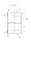
- Fig. 1 is an external view of a cylindrical body of a fiber drum showing one embodiment of the present invention and Fig. 2 is a front view showing the cross section of one side of the cylindrical body. Fig. 3 is a partially enlarged cross sectional view of the cylindrical body.
- the cylindrical body 1 of the fiber drum comprises a roll 2 made of a paper material and a protective tape 3 of a paper material provided as a protective member.
- the roll 2 may be fabricated by rolling a thick paper board into a cylindrical form or a plurality of paper sheets into a multi-layer form which will be explained later in more detail.
- the protective tape 3 may be a length of craft tape having an adhesive coating provided on the back side thereof .
- one edge at one opening 4 of the roll 2 is inwardly curled to form a curled portion 5 of an annular form which extends circumferentially and has an oval shape in the cross section.
- the protective tape 3 is bonded to the circumference of the curled portion 5.
- the curled portion 5 is pressed down together with the protective tape 3 so that its inner cavity is eliminated.
- the edge at the other opening end 6 of the roll 2 is curled to have a curled portion 7 which is identical in the shape to the curled portion 5 provided at the edge of the opening end 4.
- the curled portion 7 like the curled portion 5 is protected with another protective tape 3 and pressed down by the same manner.
- both the roll 2 and the protective tape 3 of the cylindrical body 1 are made of paper materials, they need not separation during the disposal process of the cylindrical body 1 but can easily be recycled for reuse.
- the two curled portions 5 and 7 are protected with the corresponding protective tapes 3 and even if they are wrinkled and injured when being curled and thus produce paper dusts, the protective tapes 3 can inhibit the paper dusts from being scattered out to the outside.
- curled portions 5 and 7 are pressed down so that their inner cavities are eliminated and their physical strength will be increased.
- the protective tapes 3 of the embodiment is made of, but not limited to, the craft tape having the adhesive layer provided on the back side thereof.
- the protective tapes 3 may be made of a synthetic resin material such as poly-propylene tape or cellophane tape. Those materials of tape can equally inhibit paper dusts generated at the reinforcement of the opening end or any crack of the edge from being scattered out.
- the method starts with a step of forming a green cylindrical body la as shown in Fig. 4. More specifically, a length of paper sheet S coated at its upper side with an adhesive Q before curing is wound in seven to eight layers on the mandrel of a drum forming machine (not shown) to form a roll 2 of the green cylindrical body 1a.
- the adhesive Q may be any commercially available hydrophilic adhesive composed mainly of e.g. poly-vinyl acetate emulsion or poly-vinyl alcohol.
- a protective tape (a protective member) 3 of a paper material which has an adhesive coating provided on the back side thereof and a synthetic resin coating provided on the front side thereof is circumferentially applied to the outer surface of each of edges 81 and 82 at both opening ends of the green cylindrical body la, hence completing the roll 2.
- the width of the protective tapes 3 are so sized as to cover completely the curled ends 5a and 7a of their respective curled portions 5 and 7 (See Figs. 2 and 3).
- the protective tapes 3 may be applied as slightly spaced from the opening edges 81 and 82 so long as covering completely the curled ends 5a and 7a of the curled portions 5 and 7.
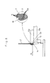
- the roll 2 is then transferred to a curled portion forming step which may be carried out by a forming machine M shown in Fig. 6.
- the forming machine M performs a sequence of three steps, (1) the first step of inwardly curling both edges 81 and 82 of the roll 2, (2) the second step of increasing the cross section of each inwardly curled portion radially and outwardly, and (3) the third step of pressing down the inwardly curled portions.
- the formingmachine M has a forming die 9 of substantially a circular shape in the plan view placed on a platform 10 supported by the floor bed and fixedly held at an intermediate of its outer side with an annular chuck support 11.
- a first chuck 12a and a second chuck 12b which travel forward and backward on the horizontal are provided on the upper side of the chuck support 11.
- the first chuck 12a located upper has a guide region 13 provided on the inner wall thereof for inwardly curling the edge of the roll with its guiding surface 131.
- the inner wall of the second chuck 12b located lower is a taper surface 14 which is tilted to increase the opening towards the lower end and opposite to a taper surface 14 of the outer side of the forming die 9 tilted at the same angle.
- a vertically movable pressing member 16 is provided precisely above the forming die 9 for pressing down the roll 2 against the forming die 9.
- Fig. 7 illustrates the edge at the other opening 6 for simplicity of the description, the edge at the one opening 4 of the roll 2 can also be shaped after turned up side down.
- the opening edge 81 moves along and on the guiding surface 131 as shown in Fig. 8.
- the edge 81 is inwardly curled to form the curled portions 5 and 7.
- the inner layers of the paper sheet S of the roll 2 lag behind the outer layers due to a difference in the curvature radius at the curled portion 5 or 7.
- the layers of the paper sheet S when curled are not separated but remain bonded to each other by the action of the adhesive Q.
- the adhesive serves as a lubricant to assist the lagging.
- portions of the adhesive Q between the layers of the edge 81 of the roll 2 are squeezed out hence running over the inner side of the roll 2.
- the portions of the adhesive Q may contribute to the higher adhesivity and when cured, the improved rigidity of the curled portions 5 and 7.
- the curled portions 5 and 7 of the roll 2 are formed at the one opening 4 and the other opening 6 respectively.
- the curled portions 5 and 7 are instantly formed in a sequence. Then, as the adhesive Q is cured between the layers of the paper sheet thus to turn to an adhesive Qa, the curled portions 5 and 7 are increased in the rigidity.
- the tilted curled portion 7 is held directly with the taper surface 15 of the forming die 9 and then the second chuck 12b is advanced in the direction X denoted by the arrow in Fig. 10 to press down the curled portion 7.
- Any hollow space in the curled portion 7 may decline the physical strength at the opening of the roll 2.
- the pressing down of the curled portion 7 may require a pressing force to prevent formation of any hollow space.
- the curled portions 5 and 7 are covered with the protective tapes 3. Accordingly, the curled portions 5 and 7 are not only reinforced in rigidity but also can be prevented from its paper dusts at any crack being scattered out. Also, as the protective tapes 3 are applied at a fair tension, they can protect the curled portions 5 and 7 from being cracked and when any crack is developed, may minimize its effect. Moreover, as the protective tapes 3 are slippery on the upper side, they allow the edges 81 and 82 to slide directly on the guiding surface 131 and the taper surface 14 of the forming die 9 until the curled portions 5 and 7 are completed. Accordingly, the curled portions 5 and 7 are less susceptible to the cracking or injury.
- the body is heated up for softening the adhesive Q between the layers of its paper sheet. If the adhesive Q is of a hot melting type, it has to be heated to higher than its melting point.
- curled portions 5 and 7 of the embodiment are fabricated, but not limited to, by inwardly curling the two edges 81 and 82 at both opening ends 4 and 6 of the roll 2, they may be shaped by any other manner.
- each edge 81 (82) of the roll 2 may inwardly be folded down to form a curled portion 51 (71).
- the folded ends 5a and 7a of their respective curled portions are equally protected with protective tapes, their physical strength at the opening will be enhanced.
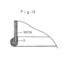
- the protective tapes 3 may be applied circumferentially to the inner sides of the opening edges 81 and 82 at both ends of a green cylindrical body la to form a roll 2 as shown in Fig. 13. Then, each opening edge 81 (82) at one opening 4 or other opening 6 of the roll 2 is outwardly curled to form a curled portion 52 (72), as shown in Figs. 12 to 14. Alternatively, each opening edge 81 (82) of the roll 2 may outwardly be folded down to have a curled portion 53 (73) as shown in Fig. 15. In any case, the generation of paper dusts can be inhibited while the physical strength of the edge at each opening is improved.
- the above embodiments of the present invention are not limited to the opening edges 81 and 82 provided with their respective curled or folded portions 5 (51, 52, or 53) and 7 (71, 72, or 73) but may permit one of the two opening edges 81 and 82 to be accompanied with the curled or folded portion.
Landscapes
- Engineering & Computer Science (AREA)
- Mechanical Engineering (AREA)
- Making Paper Articles (AREA)
- Storage Of Web-Like Or Filamentary Materials (AREA)
Applications Claiming Priority (2)
| Application Number | Priority Date | Filing Date | Title |
|---|---|---|---|
| JP2000080334A JP3678970B2 (ja) | 2000-03-22 | 2000-03-22 | ファイバードラムの筒状本体およびその製造方法 |
| JP2000080334 | 2000-03-22 |
Publications (2)
| Publication Number | Publication Date |
|---|---|
| EP1136249A1 true EP1136249A1 (de) | 2001-09-26 |
| EP1136249B1 EP1136249B1 (de) | 2004-08-04 |
Family
ID=18597455
Family Applications (1)
| Application Number | Title | Priority Date | Filing Date |
|---|---|---|---|
| EP20010302044 Expired - Lifetime EP1136249B1 (de) | 2000-03-22 | 2001-03-06 | Zylindrische Papiertrommel und Herstellungsverfahren dafür |
Country Status (5)
| Country | Link |
|---|---|
| US (1) | US6502741B2 (de) |
| EP (1) | EP1136249B1 (de) |
| JP (1) | JP3678970B2 (de) |
| AT (1) | ATE272494T1 (de) |
| DE (1) | DE60104585D1 (de) |
Cited By (1)
| Publication number | Priority date | Publication date | Assignee | Title |
|---|---|---|---|---|
| EP1223108B1 (de) * | 1999-07-21 | 2006-08-23 | Taiyo Sealpack Co. Ltd. | Faserstofftrommel, zylindrischer Körper desselben, und Verfahren zur Herstellung des zylindrischen Körpers |
Families Citing this family (4)
| Publication number | Priority date | Publication date | Assignee | Title |
|---|---|---|---|---|
| TWM353719U (en) * | 2008-07-25 | 2009-04-01 | Ming-Hsiao Lai | Toilet brush and container thereof |
| WO2012111213A1 (ja) * | 2011-02-14 | 2012-08-23 | 本田技研工業株式会社 | 金属リング製造方法及びその装置 |
| JP7088798B2 (ja) * | 2018-09-25 | 2022-06-21 | 東洋アルミエコープロダクツ株式会社 | 巻き芯 |
| KR102886930B1 (ko) * | 2024-08-20 | 2025-11-17 | (주)대덕정밀 | 산업용 다목적 종이통 |
Citations (4)
| Publication number | Priority date | Publication date | Assignee | Title |
|---|---|---|---|---|
| EP0458662A2 (de) * | 1990-05-18 | 1991-11-27 | Sonoco Products Company | Kunststoff-Verkleidung für den Rand eines Faserstoffasses |
| GB2266490A (en) * | 1992-04-22 | 1993-11-03 | Fibre Drums | Manufacturing fibre drums |
| GB2314827A (en) * | 1996-06-27 | 1998-01-14 | Robinson & Sons Ltd | Paperboard tube with beaded end |
| FR2766459A1 (fr) * | 1997-07-24 | 1999-01-29 | Abzac Sa | Couronne annulaire de protection et de renfort pour la base d'un fut en carton et fut en carton equipe de cette couronne |
Family Cites Families (23)
| Publication number | Priority date | Publication date | Assignee | Title |
|---|---|---|---|---|
| US1031615A (en) | 1911-02-28 | 1912-07-02 | Single Service Package Corp Am | Closure for vessels. |
| US1096880A (en) | 1913-07-15 | 1914-05-19 | Wilbur L Wright | Neck formation for paper receptacles. |
| US1256933A (en) * | 1915-02-01 | 1918-02-19 | Charles F Schriner | Means for reinforcing open end of metallic receptacles. |
| US1462443A (en) | 1916-08-21 | 1923-07-17 | Nat Paper Can Company | Paper can or carton |
| US1301840A (en) | 1918-07-06 | 1919-04-29 | Edwin C Hawkins | Waterproofed paper container. |
| US1700742A (en) | 1920-07-31 | 1929-02-05 | Clarke Moore Corp | Paper container |
| US1685370A (en) | 1923-11-05 | 1928-09-25 | Moore Arlington | Paper container having body with renitent neck and process of making same |
| US1796075A (en) | 1929-06-15 | 1931-03-10 | John J Kriesmer | Manufacture of paper containers |
| US1912884A (en) | 1931-03-05 | 1933-06-06 | Bodor Andrew | Paper bottle |
| US2120900A (en) | 1935-05-02 | 1938-06-14 | Humoco Corp | Fiber container and method of making the same |
| US2141556A (en) | 1935-09-17 | 1938-12-27 | Lily Tulip Cup Corp | Sealed container |
| GB492163A (en) | 1937-02-15 | 1938-09-15 | Albert Beran | Improvements in cartons or like containers more especially for liquids and in methods of producing same |
| US2406758A (en) | 1942-08-07 | 1946-09-03 | Continental Can Co | Container made of paper and method of making the same |
| US2623681A (en) | 1948-09-04 | 1952-12-30 | Oswego Fails Corp | Container body and method of making same |
| US2641827A (en) | 1949-06-16 | 1953-06-16 | Carpenter Container Corp | Method of making fiber drums having metal closures |
| US2633095A (en) * | 1950-12-28 | 1953-03-31 | American Can Co | Method of forming end seams in composite containers |
| US3381594A (en) * | 1965-05-27 | 1968-05-07 | R C Can Co | Liquid package and process for producing the same |
| GB1604253A (en) * | 1977-07-20 | 1981-12-09 | Rolex Paper Co Ltd | Tubular container |
| US4538758A (en) * | 1979-10-11 | 1985-09-03 | Automated Container Corporation | Composite container |
| US4375969A (en) * | 1979-11-16 | 1983-03-08 | Boise Cascade Corporation | Method for forming a composite container including a reversely curled body member |
| US4368841A (en) * | 1980-08-07 | 1983-01-18 | Phillips Petroleum Company | Paper container |
| US4557414A (en) * | 1981-07-14 | 1985-12-10 | Boise Cascade Corporation | Membrane-type end closure member |
| US4890786A (en) * | 1988-10-11 | 1990-01-02 | Sonoco Products Company | Fibre drum with reinforcement collar |
-
2000
- 2000-03-22 JP JP2000080334A patent/JP3678970B2/ja not_active Expired - Lifetime
-
2001
- 2001-03-06 DE DE60104585T patent/DE60104585D1/de not_active Expired - Lifetime
- 2001-03-06 EP EP20010302044 patent/EP1136249B1/de not_active Expired - Lifetime
- 2001-03-06 AT AT01302044T patent/ATE272494T1/de not_active IP Right Cessation
- 2001-03-22 US US09/813,943 patent/US6502741B2/en not_active Expired - Lifetime
Patent Citations (4)
| Publication number | Priority date | Publication date | Assignee | Title |
|---|---|---|---|---|
| EP0458662A2 (de) * | 1990-05-18 | 1991-11-27 | Sonoco Products Company | Kunststoff-Verkleidung für den Rand eines Faserstoffasses |
| GB2266490A (en) * | 1992-04-22 | 1993-11-03 | Fibre Drums | Manufacturing fibre drums |
| GB2314827A (en) * | 1996-06-27 | 1998-01-14 | Robinson & Sons Ltd | Paperboard tube with beaded end |
| FR2766459A1 (fr) * | 1997-07-24 | 1999-01-29 | Abzac Sa | Couronne annulaire de protection et de renfort pour la base d'un fut en carton et fut en carton equipe de cette couronne |
Cited By (1)
| Publication number | Priority date | Publication date | Assignee | Title |
|---|---|---|---|---|
| EP1223108B1 (de) * | 1999-07-21 | 2006-08-23 | Taiyo Sealpack Co. Ltd. | Faserstofftrommel, zylindrischer Körper desselben, und Verfahren zur Herstellung des zylindrischen Körpers |
Also Published As
| Publication number | Publication date |
|---|---|
| JP3678970B2 (ja) | 2005-08-03 |
| US20010023890A1 (en) | 2001-09-27 |
| EP1136249B1 (de) | 2004-08-04 |
| DE60104585D1 (de) | 2004-09-09 |
| US6502741B2 (en) | 2003-01-07 |
| JP2001270513A (ja) | 2001-10-02 |
| ATE272494T1 (de) | 2004-08-15 |
Similar Documents
| Publication | Publication Date | Title |
|---|---|---|
| EP0626254B1 (de) | Verfahren und Vorrichtung zum Formen einer nach aussen gerollten Lippe auf einem zylindrischen Behälterkörper | |
| EP1136249B1 (de) | Zylindrische Papiertrommel und Herstellungsverfahren dafür | |
| GB2081201A (en) | Paper containers | |
| ITTO20011161A1 (it) | Metodo per la realizzazione di un involucro coibentato per un propulsore a razzo, ed involucro coibentato per un propulsore a razzo realizza | |
| MX2007011194A (es) | Tubo enrollado en espiral con vacios y metodo para fabricar el mismo. | |
| EP1033239B1 (de) | Vorrichtung zum Herstellen einer auswärts gebördelten Lippe auf einem zylindrischen Behälterkörper | |
| KR100335531B1 (ko) | 재료의 롤, 재료의 롤을 제조하는 방법 및 상기 방법을 실시하기 위한 장치 | |
| EP1223108B1 (de) | Faserstofftrommel, zylindrischer Körper desselben, und Verfahren zur Herstellung des zylindrischen Körpers | |
| US3736972A (en) | Pneumatic tire and method for the manufacture thereof | |
| EP0454377A1 (de) | Verfahren zur Gestaltung und Kopplung von Kunststoffolien | |
| US1967060A (en) | Steel core for steering wheels and the like | |
| AU582845B2 (en) | Cup rim and method | |
| US5979530A (en) | Separator sheet-feeding apparatus | |
| JPH0713124Y2 (ja) | ラミネートテープ成形ロール | |
| RU2768681C2 (ru) | Упаковочный контейнер и плёнка для его изготовления | |
| JP6581492B2 (ja) | インナーライナー部材及びタイヤの製造方法 | |
| JPS6035404B2 (ja) | 超硬合金製複合物品の製造法 | |
| US1214288A (en) | Steering-wheel rim. | |
| JPS59171617A (ja) | Frp成形体の製造方法 | |
| CA2343283A1 (en) | Method for fabricating composite pressure vessels and products fabricated by the method | |
| GB2292369A (en) | Paper core for rolled thin film | |
| JPH08309893A (ja) | 梱包・包装用部材の製造方法 | |
| JPS6359943B2 (de) | ||
| JP7088798B2 (ja) | 巻き芯 | |
| JPH064282B2 (ja) | ラミネートテープの成形方法及びそれに使用するダイス |
Legal Events
| Date | Code | Title | Description |
|---|---|---|---|
| PUAI | Public reference made under article 153(3) epc to a published international application that has entered the european phase |
Free format text: ORIGINAL CODE: 0009012 |
|
| AK | Designated contracting states |
Kind code of ref document: A1 Designated state(s): AT BE CH CY DE DK ES FI FR GB GR IE IT LI LU MC NL PT SE TR |
|
| AX | Request for extension of the european patent |
Free format text: AL;LT;LV;MK;RO;SI |
|
| 17P | Request for examination filed |
Effective date: 20020107 |
|
| AKX | Designation fees paid |
Free format text: AT BE CH CY DE DK ES FI FR GB GR IE IT LI LU MC NL PT SE TR |
|
| AXX | Extension fees paid |
Free format text: AL PAYMENT 20020320;LT PAYMENT 20020320;LV PAYMENT 20020320;MK PAYMENT 20020320;RO PAYMENT 20020320;SI PAYMENT 20020320 |
|
| 17Q | First examination report despatched |
Effective date: 20030326 |
|
| GRAP | Despatch of communication of intention to grant a patent |
Free format text: ORIGINAL CODE: EPIDOSNIGR1 |
|
| GRAS | Grant fee paid |
Free format text: ORIGINAL CODE: EPIDOSNIGR3 |
|
| GRAA | (expected) grant |
Free format text: ORIGINAL CODE: 0009210 |
|
| AK | Designated contracting states |
Kind code of ref document: B1 Designated state(s): AT BE CH CY DE DK ES FI FR GB GR IE IT LI LU MC NL PT SE TR |
|
| AX | Request for extension of the european patent |
Extension state: AL LT LV MK RO SI |
|
| PG25 | Lapsed in a contracting state [announced via postgrant information from national office to epo] |
Ref country code: IT Free format text: LAPSE BECAUSE OF FAILURE TO SUBMIT A TRANSLATION OF THE DESCRIPTION OR TO PAY THE FEE WITHIN THE PRESCRIBED TIME-LIMIT;WARNING: LAPSES OF ITALIAN PATENTS WITH EFFECTIVE DATE BEFORE 2007 MAY HAVE OCCURRED AT ANY TIME BEFORE 2007. THE CORRECT EFFECTIVE DATE MAY BE DIFFERENT FROM THE ONE RECORDED. Effective date: 20040804 Ref country code: BE Free format text: LAPSE BECAUSE OF FAILURE TO SUBMIT A TRANSLATION OF THE DESCRIPTION OR TO PAY THE FEE WITHIN THE PRESCRIBED TIME-LIMIT Effective date: 20040804 Ref country code: FR Free format text: LAPSE BECAUSE OF FAILURE TO SUBMIT A TRANSLATION OF THE DESCRIPTION OR TO PAY THE FEE WITHIN THE PRESCRIBED TIME-LIMIT Effective date: 20040804 Ref country code: LI Free format text: LAPSE BECAUSE OF FAILURE TO SUBMIT A TRANSLATION OF THE DESCRIPTION OR TO PAY THE FEE WITHIN THE PRESCRIBED TIME-LIMIT Effective date: 20040804 Ref country code: TR Free format text: LAPSE BECAUSE OF FAILURE TO SUBMIT A TRANSLATION OF THE DESCRIPTION OR TO PAY THE FEE WITHIN THE PRESCRIBED TIME-LIMIT Effective date: 20040804 Ref country code: FI Free format text: LAPSE BECAUSE OF FAILURE TO SUBMIT A TRANSLATION OF THE DESCRIPTION OR TO PAY THE FEE WITHIN THE PRESCRIBED TIME-LIMIT Effective date: 20040804 Ref country code: NL Free format text: LAPSE BECAUSE OF FAILURE TO SUBMIT A TRANSLATION OF THE DESCRIPTION OR TO PAY THE FEE WITHIN THE PRESCRIBED TIME-LIMIT Effective date: 20040804 Ref country code: CH Free format text: LAPSE BECAUSE OF FAILURE TO SUBMIT A TRANSLATION OF THE DESCRIPTION OR TO PAY THE FEE WITHIN THE PRESCRIBED TIME-LIMIT Effective date: 20040804 Ref country code: AT Free format text: LAPSE BECAUSE OF FAILURE TO SUBMIT A TRANSLATION OF THE DESCRIPTION OR TO PAY THE FEE WITHIN THE PRESCRIBED TIME-LIMIT Effective date: 20040804 |
|
| REG | Reference to a national code |
Ref country code: GB Ref legal event code: FG4D |
|
| REG | Reference to a national code |
Ref country code: CH Ref legal event code: EP |
|
| REG | Reference to a national code |
Ref country code: IE Ref legal event code: FG4D |
|
| REF | Corresponds to: |
Ref document number: 60104585 Country of ref document: DE Date of ref document: 20040909 Kind code of ref document: P |
|
| PG25 | Lapsed in a contracting state [announced via postgrant information from national office to epo] |
Ref country code: DK Free format text: LAPSE BECAUSE OF FAILURE TO SUBMIT A TRANSLATION OF THE DESCRIPTION OR TO PAY THE FEE WITHIN THE PRESCRIBED TIME-LIMIT Effective date: 20041104 Ref country code: GR Free format text: LAPSE BECAUSE OF FAILURE TO SUBMIT A TRANSLATION OF THE DESCRIPTION OR TO PAY THE FEE WITHIN THE PRESCRIBED TIME-LIMIT Effective date: 20041104 Ref country code: SE Free format text: LAPSE BECAUSE OF FAILURE TO SUBMIT A TRANSLATION OF THE DESCRIPTION OR TO PAY THE FEE WITHIN THE PRESCRIBED TIME-LIMIT Effective date: 20041104 |
|
| PG25 | Lapsed in a contracting state [announced via postgrant information from national office to epo] |
Ref country code: DE Free format text: LAPSE BECAUSE OF FAILURE TO SUBMIT A TRANSLATION OF THE DESCRIPTION OR TO PAY THE FEE WITHIN THE PRESCRIBED TIME-LIMIT Effective date: 20041105 |
|
| PG25 | Lapsed in a contracting state [announced via postgrant information from national office to epo] |
Ref country code: ES Free format text: LAPSE BECAUSE OF FAILURE TO SUBMIT A TRANSLATION OF THE DESCRIPTION OR TO PAY THE FEE WITHIN THE PRESCRIBED TIME-LIMIT Effective date: 20041115 |
|
| NLV1 | Nl: lapsed or annulled due to failure to fulfill the requirements of art. 29p and 29m of the patents act | ||
| LTIE | Lt: invalidation of european patent or patent extension |
Effective date: 20040804 |
|
| REG | Reference to a national code |
Ref country code: CH Ref legal event code: PL |
|
| PG25 | Lapsed in a contracting state [announced via postgrant information from national office to epo] |
Ref country code: CY Free format text: LAPSE BECAUSE OF FAILURE TO SUBMIT A TRANSLATION OF THE DESCRIPTION OR TO PAY THE FEE WITHIN THE PRESCRIBED TIME-LIMIT Effective date: 20050306 Ref country code: LU Free format text: LAPSE BECAUSE OF NON-PAYMENT OF DUE FEES Effective date: 20050306 |
|
| PG25 | Lapsed in a contracting state [announced via postgrant information from national office to epo] |
Ref country code: IE Free format text: LAPSE BECAUSE OF NON-PAYMENT OF DUE FEES Effective date: 20050307 |
|
| PG25 | Lapsed in a contracting state [announced via postgrant information from national office to epo] |
Ref country code: MC Free format text: LAPSE BECAUSE OF NON-PAYMENT OF DUE FEES Effective date: 20050331 |
|
| PLBE | No opposition filed within time limit |
Free format text: ORIGINAL CODE: 0009261 |
|
| STAA | Information on the status of an ep patent application or granted ep patent |
Free format text: STATUS: NO OPPOSITION FILED WITHIN TIME LIMIT |
|
| 26N | No opposition filed |
Effective date: 20050506 |
|
| EN | Fr: translation not filed | ||
| REG | Reference to a national code |
Ref country code: IE Ref legal event code: MM4A |
|
| PG25 | Lapsed in a contracting state [announced via postgrant information from national office to epo] |
Ref country code: PT Free format text: LAPSE BECAUSE OF NON-PAYMENT OF DUE FEES Effective date: 20050104 |
|
| PGFP | Annual fee paid to national office [announced via postgrant information from national office to epo] |
Ref country code: GB Payment date: 20170301 Year of fee payment: 17 |
|
| GBPC | Gb: european patent ceased through non-payment of renewal fee |
Effective date: 20180306 |
|
| PG25 | Lapsed in a contracting state [announced via postgrant information from national office to epo] |
Ref country code: GB Free format text: LAPSE BECAUSE OF NON-PAYMENT OF DUE FEES Effective date: 20180306 |