EP1136304A2 - Beschleunigungsüberwachungseinrichtung eines Fahrzeuges - Google Patents
Beschleunigungsüberwachungseinrichtung eines Fahrzeuges Download PDFInfo
- Publication number
- EP1136304A2 EP1136304A2 EP01302352A EP01302352A EP1136304A2 EP 1136304 A2 EP1136304 A2 EP 1136304A2 EP 01302352 A EP01302352 A EP 01302352A EP 01302352 A EP01302352 A EP 01302352A EP 1136304 A2 EP1136304 A2 EP 1136304A2
- Authority
- EP
- European Patent Office
- Prior art keywords
- acceleration
- vehicle
- sensor
- vehicle acceleration
- actual
- Prior art date
- Legal status (The legal status is an assumption and is not a legal conclusion. Google has not performed a legal analysis and makes no representation as to the accuracy of the status listed.)
- Withdrawn
Links
Images



Classifications
-
- B—PERFORMING OPERATIONS; TRANSPORTING
- B60—VEHICLES IN GENERAL
- B60K—ARRANGEMENT OR MOUNTING OF PROPULSION UNITS OR OF TRANSMISSIONS IN VEHICLES; ARRANGEMENT OR MOUNTING OF PLURAL DIVERSE PRIME-MOVERS IN VEHICLES; AUXILIARY DRIVES FOR VEHICLES; INSTRUMENTATION OR DASHBOARDS FOR VEHICLES; ARRANGEMENTS IN CONNECTION WITH COOLING, AIR INTAKE, GAS EXHAUST OR FUEL SUPPLY OF PROPULSION UNITS IN VEHICLES
- B60K6/00—Arrangement or mounting of plural diverse prime-movers for mutual or common propulsion, e.g. hybrid propulsion systems comprising electric motors and internal combustion engines
- B60K6/20—Arrangement or mounting of plural diverse prime-movers for mutual or common propulsion, e.g. hybrid propulsion systems comprising electric motors and internal combustion engines the prime-movers consisting of electric motors and internal combustion engines, e.g. HEVs
- B60K6/42—Arrangement or mounting of plural diverse prime-movers for mutual or common propulsion, e.g. hybrid propulsion systems comprising electric motors and internal combustion engines the prime-movers consisting of electric motors and internal combustion engines, e.g. HEVs characterised by the architecture of the hybrid electric vehicle
- B60K6/48—Parallel type
-
- B—PERFORMING OPERATIONS; TRANSPORTING
- B60—VEHICLES IN GENERAL
- B60W—CONJOINT CONTROL OF VEHICLE SUB-UNITS OF DIFFERENT TYPE OR DIFFERENT FUNCTION; CONTROL SYSTEMS SPECIALLY ADAPTED FOR HYBRID VEHICLES; ROAD VEHICLE DRIVE CONTROL SYSTEMS FOR PURPOSES NOT RELATED TO THE CONTROL OF A PARTICULAR SUB-UNIT
- B60W20/00—Control systems specially adapted for hybrid vehicles
- B60W20/10—Controlling the power contribution of each of the prime movers to meet required power demand
- B60W20/11—Controlling the power contribution of each of the prime movers to meet required power demand using model predictive control [MPC] strategies, i.e. control methods based on models predicting performance
-
- B—PERFORMING OPERATIONS; TRANSPORTING
- B60—VEHICLES IN GENERAL
- B60K—ARRANGEMENT OR MOUNTING OF PROPULSION UNITS OR OF TRANSMISSIONS IN VEHICLES; ARRANGEMENT OR MOUNTING OF PLURAL DIVERSE PRIME-MOVERS IN VEHICLES; AUXILIARY DRIVES FOR VEHICLES; INSTRUMENTATION OR DASHBOARDS FOR VEHICLES; ARRANGEMENTS IN CONNECTION WITH COOLING, AIR INTAKE, GAS EXHAUST OR FUEL SUPPLY OF PROPULSION UNITS IN VEHICLES
- B60K31/00—Vehicle fittings, acting on a single sub-unit only, for automatically controlling vehicle speed, i.e. preventing speed from exceeding an arbitrarily established velocity or maintaining speed at a particular velocity, as selected by the vehicle operator
- B60K31/02—Vehicle fittings, acting on a single sub-unit only, for automatically controlling vehicle speed, i.e. preventing speed from exceeding an arbitrarily established velocity or maintaining speed at a particular velocity, as selected by the vehicle operator including electrically actuated servomechanism
- B60K31/04—Vehicle fittings, acting on a single sub-unit only, for automatically controlling vehicle speed, i.e. preventing speed from exceeding an arbitrarily established velocity or maintaining speed at a particular velocity, as selected by the vehicle operator including electrically actuated servomechanism and means for comparing one electrical quantity, e.g. voltage, pulse, waveform, flux, or the like, with another quantity of a like kind, which comparison means is involved in the development of an electrical signal which is fed into the controlling means
- B60K31/042—Vehicle fittings, acting on a single sub-unit only, for automatically controlling vehicle speed, i.e. preventing speed from exceeding an arbitrarily established velocity or maintaining speed at a particular velocity, as selected by the vehicle operator including electrically actuated servomechanism and means for comparing one electrical quantity, e.g. voltage, pulse, waveform, flux, or the like, with another quantity of a like kind, which comparison means is involved in the development of an electrical signal which is fed into the controlling means where at least one electrical quantity is set by the vehicle operator
- B60K31/045—Vehicle fittings, acting on a single sub-unit only, for automatically controlling vehicle speed, i.e. preventing speed from exceeding an arbitrarily established velocity or maintaining speed at a particular velocity, as selected by the vehicle operator including electrically actuated servomechanism and means for comparing one electrical quantity, e.g. voltage, pulse, waveform, flux, or the like, with another quantity of a like kind, which comparison means is involved in the development of an electrical signal which is fed into the controlling means where at least one electrical quantity is set by the vehicle operator in a memory, e.g. a capacitor
- B60K31/047—Vehicle fittings, acting on a single sub-unit only, for automatically controlling vehicle speed, i.e. preventing speed from exceeding an arbitrarily established velocity or maintaining speed at a particular velocity, as selected by the vehicle operator including electrically actuated servomechanism and means for comparing one electrical quantity, e.g. voltage, pulse, waveform, flux, or the like, with another quantity of a like kind, which comparison means is involved in the development of an electrical signal which is fed into the controlling means where at least one electrical quantity is set by the vehicle operator in a memory, e.g. a capacitor the memory being digital
-
- B—PERFORMING OPERATIONS; TRANSPORTING
- B60—VEHICLES IN GENERAL
- B60K—ARRANGEMENT OR MOUNTING OF PROPULSION UNITS OR OF TRANSMISSIONS IN VEHICLES; ARRANGEMENT OR MOUNTING OF PLURAL DIVERSE PRIME-MOVERS IN VEHICLES; AUXILIARY DRIVES FOR VEHICLES; INSTRUMENTATION OR DASHBOARDS FOR VEHICLES; ARRANGEMENTS IN CONNECTION WITH COOLING, AIR INTAKE, GAS EXHAUST OR FUEL SUPPLY OF PROPULSION UNITS IN VEHICLES
- B60K6/00—Arrangement or mounting of plural diverse prime-movers for mutual or common propulsion, e.g. hybrid propulsion systems comprising electric motors and internal combustion engines
- B60K6/20—Arrangement or mounting of plural diverse prime-movers for mutual or common propulsion, e.g. hybrid propulsion systems comprising electric motors and internal combustion engines the prime-movers consisting of electric motors and internal combustion engines, e.g. HEVs
- B60K6/50—Architecture of the driveline characterised by arrangement or kind of transmission units
- B60K6/52—Driving a plurality of drive axles, e.g. four-wheel drive
-
- B—PERFORMING OPERATIONS; TRANSPORTING
- B60—VEHICLES IN GENERAL
- B60W—CONJOINT CONTROL OF VEHICLE SUB-UNITS OF DIFFERENT TYPE OR DIFFERENT FUNCTION; CONTROL SYSTEMS SPECIALLY ADAPTED FOR HYBRID VEHICLES; ROAD VEHICLE DRIVE CONTROL SYSTEMS FOR PURPOSES NOT RELATED TO THE CONTROL OF A PARTICULAR SUB-UNIT
- B60W10/00—Conjoint control of vehicle sub-units of different type or different function
- B60W10/04—Conjoint control of vehicle sub-units of different type or different function including control of propulsion units
- B60W10/06—Conjoint control of vehicle sub-units of different type or different function including control of propulsion units including control of combustion engines
-
- B—PERFORMING OPERATIONS; TRANSPORTING
- B60—VEHICLES IN GENERAL
- B60W—CONJOINT CONTROL OF VEHICLE SUB-UNITS OF DIFFERENT TYPE OR DIFFERENT FUNCTION; CONTROL SYSTEMS SPECIALLY ADAPTED FOR HYBRID VEHICLES; ROAD VEHICLE DRIVE CONTROL SYSTEMS FOR PURPOSES NOT RELATED TO THE CONTROL OF A PARTICULAR SUB-UNIT
- B60W10/00—Conjoint control of vehicle sub-units of different type or different function
- B60W10/04—Conjoint control of vehicle sub-units of different type or different function including control of propulsion units
- B60W10/08—Conjoint control of vehicle sub-units of different type or different function including control of propulsion units including control of electric propulsion units, e.g. motors or generators
-
- B—PERFORMING OPERATIONS; TRANSPORTING
- B60—VEHICLES IN GENERAL
- B60W—CONJOINT CONTROL OF VEHICLE SUB-UNITS OF DIFFERENT TYPE OR DIFFERENT FUNCTION; CONTROL SYSTEMS SPECIALLY ADAPTED FOR HYBRID VEHICLES; ROAD VEHICLE DRIVE CONTROL SYSTEMS FOR PURPOSES NOT RELATED TO THE CONTROL OF A PARTICULAR SUB-UNIT
- B60W10/00—Conjoint control of vehicle sub-units of different type or different function
- B60W10/10—Conjoint control of vehicle sub-units of different type or different function including control of change-speed gearings
-
- B—PERFORMING OPERATIONS; TRANSPORTING
- B60—VEHICLES IN GENERAL
- B60W—CONJOINT CONTROL OF VEHICLE SUB-UNITS OF DIFFERENT TYPE OR DIFFERENT FUNCTION; CONTROL SYSTEMS SPECIALLY ADAPTED FOR HYBRID VEHICLES; ROAD VEHICLE DRIVE CONTROL SYSTEMS FOR PURPOSES NOT RELATED TO THE CONTROL OF A PARTICULAR SUB-UNIT
- B60W20/00—Control systems specially adapted for hybrid vehicles
-
- B—PERFORMING OPERATIONS; TRANSPORTING
- B60—VEHICLES IN GENERAL
- B60R—VEHICLES, VEHICLE FITTINGS, OR VEHICLE PARTS, NOT OTHERWISE PROVIDED FOR
- B60R21/00—Arrangements or fittings on vehicles for protecting or preventing injuries to occupants or pedestrians in case of accidents or other traffic risks
- B60R21/01—Electrical circuits for triggering passive safety arrangements, e.g. airbags, safety belt tighteners, in case of vehicle accidents or impending vehicle accidents
- B60R21/013—Electrical circuits for triggering passive safety arrangements, e.g. airbags, safety belt tighteners, in case of vehicle accidents or impending vehicle accidents including means for detecting collisions, impending collisions or roll-over
-
- B—PERFORMING OPERATIONS; TRANSPORTING
- B60—VEHICLES IN GENERAL
- B60W—CONJOINT CONTROL OF VEHICLE SUB-UNITS OF DIFFERENT TYPE OR DIFFERENT FUNCTION; CONTROL SYSTEMS SPECIALLY ADAPTED FOR HYBRID VEHICLES; ROAD VEHICLE DRIVE CONTROL SYSTEMS FOR PURPOSES NOT RELATED TO THE CONTROL OF A PARTICULAR SUB-UNIT
- B60W50/00—Details of control systems for road vehicle drive control not related to the control of a particular sub-unit, e.g. process diagnostic or vehicle driver interfaces
- B60W2050/0001—Details of the control system
- B60W2050/0019—Control system elements or transfer functions
- B60W2050/0022—Gains, weighting coefficients or weighting functions
-
- B—PERFORMING OPERATIONS; TRANSPORTING
- B60—VEHICLES IN GENERAL
- B60W—CONJOINT CONTROL OF VEHICLE SUB-UNITS OF DIFFERENT TYPE OR DIFFERENT FUNCTION; CONTROL SYSTEMS SPECIALLY ADAPTED FOR HYBRID VEHICLES; ROAD VEHICLE DRIVE CONTROL SYSTEMS FOR PURPOSES NOT RELATED TO THE CONTROL OF A PARTICULAR SUB-UNIT
- B60W2520/00—Input parameters relating to overall vehicle dynamics
- B60W2520/10—Longitudinal speed
- B60W2520/105—Longitudinal acceleration
-
- B—PERFORMING OPERATIONS; TRANSPORTING
- B60—VEHICLES IN GENERAL
- B60W—CONJOINT CONTROL OF VEHICLE SUB-UNITS OF DIFFERENT TYPE OR DIFFERENT FUNCTION; CONTROL SYSTEMS SPECIALLY ADAPTED FOR HYBRID VEHICLES; ROAD VEHICLE DRIVE CONTROL SYSTEMS FOR PURPOSES NOT RELATED TO THE CONTROL OF A PARTICULAR SUB-UNIT
- B60W2720/00—Output or target parameters relating to overall vehicle dynamics
- B60W2720/10—Longitudinal speed
- B60W2720/106—Longitudinal acceleration
-
- Y—GENERAL TAGGING OF NEW TECHNOLOGICAL DEVELOPMENTS; GENERAL TAGGING OF CROSS-SECTIONAL TECHNOLOGIES SPANNING OVER SEVERAL SECTIONS OF THE IPC; TECHNICAL SUBJECTS COVERED BY FORMER USPC CROSS-REFERENCE ART COLLECTIONS [XRACs] AND DIGESTS
- Y02—TECHNOLOGIES OR APPLICATIONS FOR MITIGATION OR ADAPTATION AGAINST CLIMATE CHANGE
- Y02T—CLIMATE CHANGE MITIGATION TECHNOLOGIES RELATED TO TRANSPORTATION
- Y02T10/00—Road transport of goods or passengers
- Y02T10/60—Other road transportation technologies with climate change mitigation effect
- Y02T10/62—Hybrid vehicles
-
- Y—GENERAL TAGGING OF NEW TECHNOLOGICAL DEVELOPMENTS; GENERAL TAGGING OF CROSS-SECTIONAL TECHNOLOGIES SPANNING OVER SEVERAL SECTIONS OF THE IPC; TECHNICAL SUBJECTS COVERED BY FORMER USPC CROSS-REFERENCE ART COLLECTIONS [XRACs] AND DIGESTS
- Y10—TECHNICAL SUBJECTS COVERED BY FORMER USPC
- Y10S—TECHNICAL SUBJECTS COVERED BY FORMER USPC CROSS-REFERENCE ART COLLECTIONS [XRACs] AND DIGESTS
- Y10S903/00—Hybrid electric vehicles, HEVS
- Y10S903/902—Prime movers comprising electrical and internal combustion motors
- Y10S903/903—Prime movers comprising electrical and internal combustion motors having energy storing means, e.g. battery, capacitor
- Y10S903/904—Component specially adapted for hev
- Y10S903/915—Specific drive or transmission adapted for hev
- Y10S903/916—Specific drive or transmission adapted for hev with plurality of drive axles
-
- Y—GENERAL TAGGING OF NEW TECHNOLOGICAL DEVELOPMENTS; GENERAL TAGGING OF CROSS-SECTIONAL TECHNOLOGIES SPANNING OVER SEVERAL SECTIONS OF THE IPC; TECHNICAL SUBJECTS COVERED BY FORMER USPC CROSS-REFERENCE ART COLLECTIONS [XRACs] AND DIGESTS
- Y10—TECHNICAL SUBJECTS COVERED BY FORMER USPC
- Y10S—TECHNICAL SUBJECTS COVERED BY FORMER USPC CROSS-REFERENCE ART COLLECTIONS [XRACs] AND DIGESTS
- Y10S903/00—Hybrid electric vehicles, HEVS
- Y10S903/902—Prime movers comprising electrical and internal combustion motors
- Y10S903/903—Prime movers comprising electrical and internal combustion motors having energy storing means, e.g. battery, capacitor
- Y10S903/945—Characterized by control of gearing, e.g. control of transmission ratio
Definitions
- the present invention relates to monitoring of electronically controlled drive units in vehicles.
- an electronically controlled throttle is used for improved performance.
- engines also may be controlled using engine output, or torque control where the actual engine torque is controlled to a desired engine torque through an output adjusting device, such as with the electronic throttle, ignition timing, air-fuel ratio, or various other devices.
- One method to monitor engine control systems determines if actual engine torque is greater than desired engine torque. Actual engine torque is determined in accordance with engine airflow and/or injected fuel amount, and various other factors. Such a method is described U.S. Patent 5,692,472.
- the inventors herein have recognised a disadvantage of the above approach.
- a method when such a method is utilised with vehicles having multiple torque sources, such as hybrid electric vehicles, several different torque values can be considered.
- torque produced by an electric motor and torque produced by an internal combustion engine can both contribute to overall drive torque.
- additional variables may be used to account for various torque sources.
- Each of these additional variables can then have redundancy.
- monitoring using the above structure may result in additional cost and/or complexity.
- the present invention provides a method for monitoring and controlling a vehicle drive system, the method comprises determining a preselected vehicle acceleration, calculating an actual vehicle acceleration based on an accelerometer coupled to the vehicle, and initiating a reaction when said actual vehicle acceleration is greater than said preselected vehicle acceleration.
- An advantage of the above aspect of the present invention is a potential for reduced system complexity and/or cost.
- a method and system embodying the present invention provide a mutually beneficial monitoring and control approach for use with vehicles having a single power source or multiple power sources.
- the present invention provides a system for a vehicle having an electronically controlled drive unit, the system comprising: a first controller that determines a desired acceleration based on an operator command and adjusts a drive unit operating parameter to achieve said desired acceleration; and a second controller that determines a preselected acceleration of the vehicle based on said desired acceleration, determines an actual vehicle acceleration based on a sensor coupled to the vehicle, and initiates a reaction when said actual vehicle acceleration is greater than said preselected acceleration.
- An advantage of the above aspect of the present invention is a potential for reduced system complexity and/or cost.
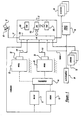
- Engine 10 and motor 11 of a vehicle are shown coupled to transmission 14.
- Engine 10 and motor 11 can be coupled in various ways known to those skilled in the art, such, for example, in a parallel fashion, a series fashion, or any combination thereof.
- Motor 11 can be an electric motor capable of supplying power to or receiving power from transmission 14.
- motor 11 can be used to provide regenerative braking or to provide the vehicle tractive force from batteries (not shown) that store energy.
- Transmission 14 is coupled to a first set of drive wheels 20.
- transmission 14 can also be coupled to a second set of drive wheels 22.
- Transmission 14 can be a combined gear set and torque converter, a continuously variable transmission, or any other power transfer unit known to those skilled in the art and suggested by this disclosure.
- accelerator pedal 40 is shown communicating with the driver's foot 42. Accelerator pedal position (PP) is measured by pedal position sensor 134 and sent to controller 12.
- PP Accelerator pedal position
- Controller 12 receives various signals from sensors coupled to engine 10, motor 11, and the vehicle, in addition to those signals previously discussed, including: first measurement of vehicle speed (VS1) of wheel 20 from sensor 30, second measurement of vehicle speed (VS2) of wheel 22 from sensor 32, measurement of vehicle acceleration (SIGNAL1) from accelerometer 50, and various other signals from sensors 52. These other signals include engine coolant temperature (ECT), and air charge temperature (ACT). Also, controller 12 sends signals to actuators 72.
- Accelerometer 50 can also be coupled to airbag system 60.
- a single sensor can be used for both an airbag system and a vehicle monitoring system.
- accelerometer 50 is capable of outputting a signal representative of vehicle acceleration at all vehicle speeds, including zero vehicle speed. In other words, determining vehicle acceleration from a vehicle speed sensor may provide degraded performance at low vehicle speeds. This is because the pickup, sometimes magnetic, which generates a signal when a certain point of the vehicle wheel rotates past the pickup. If the vehicle wheel is not rotating, no signal is produced and determinations of vehicle speed and/or vehicle acceleration are degraded.
- the accelerometer is capable of outputting a signal independent of vehicle speed, and thus the present invention can monitor even at low vehicle speeds.
- controller 12 is a conventional microcomputer including: microprocessor unit 102, input/output ports 104, electronic memory chip 106, which is an electronically programmable memory in this particular example, random access memory 108, and a conventional data bus.
- engine 10 is electronically controlled by an electronic throttle control system (not shown).
- the drive unit which in this case is engine 10, motor 11, and transmission 14, is controlled to produce a desired vehicle acceleration.
- controller 12 provides a speed control function wherein vehicle speed is controlled to a desired speed set by the vehicle driver.
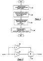
- step 200 a determination is made as to whether speed control is active.
- step 210 desired acceleration (desrate, or acc_dd_req) is determined based in part on a function (f1) of pedal position (PP) and vehicle speed (VS1) as described later herein.
- desired acceleration desrate, or acc_dd_req
- desired acceleration can also be adjusted based on actuation of the brake pedal.
- desired acceleration can also be adjusted based on the position of a gear selector.
- the level that selects P,R,N,D,L,1 (park, reverse, neutral, drive, low, low 1, etc.) is taken into account in determining desired acceleration.
- desired acceleration can be modified depending on whether a switch is set to a "sport" mode or a "fuel economy” mode. Then, in step 220, actual vehicle acceleration (actualrate) is determined as described later herein with particular reference to Figure 3.
- step 230 a determination is made as to whether actual acceleration (actualrate) is greater than the desired acceleration plus a first calibratable threshold (T1).
- timer is reset to zero in step 240. Otherwise, timer is incremented by the computer loop time (looptime) in step 250.
- step 260 a determination is made as to whether actual acceleration (actualrate) is greater than the desired acceleration plus a second calibratable threshold (T2) or timer is greater than third calibratable threshold (T3).
- threshold T2 is greater than threshold T1.
- a reaction is initiated in step 270.
- This reaction is in a preferable embodiment, decreasing engine torque.
- Engine torque can be decreased in a variety of methods, including decreasing fuel amount, decreasing air amount, retarding ignition timing, deactivating cylinders, or any other method known to those skilled in the art in view of this disclosure to reduce engine torque.
- a reaction can be changing a transmission gear ratio to produce less wheel torque or engaging ancillary devices to consume engine torque.
- a reaction may be to reduce motor torque or cause motor 11 to act as a generator, thereby absorbing energy and reducing wheel torque.
- a reaction may be to reduce vehicle acceleration by any method listed above herein.
- step 310 the routine determines a first temporary acceleration (tempratel) based on acceleration sensor 50.
- step 320 the routine determines a second temporary acceleration (temprate2) based on first vehicle speed signal (VS1).
- a derivative of vehicle speed is used.
- a lead lag filter is used to approximate a derivative and also reduce noise.
- step 330 the routine determines a third temporary acceleration (temprate3) based on second vehicle speed signal (VS2). Again, a lead lag filter can be used to approximate a derivative and also reduce noise.
- step 340 actual acceleration (actualrate) used for monitoring is determined based on a maximum of the first through third temporary accelerations.
- all three acceleration measurements are used.
- various combination of these can be used, such as, for example, the maximum of tempratel and temprate2.
- a single measurement alone can be used.
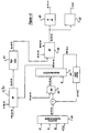
- Desired acceleration from the driver or driver demanded acceleration (acc_dd_req) is determined based on pedal position (PP) and vehicle speed (VS), with modifications for barometric pressure (BP) and engine and air temperatures (ECT, ACT) in block 410. Then, the difference between driver demanded acceleration and "droop" control output (accl_droop) is compared with desired acceleration from speed control (accl_spd_req). In particular, a maximum of these two values is determined as a arbitrated desired acceleration (accl_arb_req) from block 412. "Droop" control is described later herein with particular reference to Figure 5.
- desired acceleration from speed control is determined based on a vehicle speed error between a set speed and an actual vehicle speed.
- the vehicle speed error is used in conjunction with a non-linear gain function to produce (accl_spd_req).
- accl_spd_req is linearly related to speed error.
- the speed error limits may be, plus and minus 3 MPH, for example. Outside these speed error limits, desired acceleration may be limited to a fixed value, such as 1.5 MPH/sec, for example.
- this first arbitrated acceleration, accl_arb_req, and vehicle speed (VS) are used to control vehicle acceleration in block 414 as described with particular reference to Figure 6.
- the output of the acceleration control is a desired wheel torque value (tqw_arb_req) and a closed loop control torque (tqw_arb_cl).
- a desired wheel torque from traction control (trc_tqw_req), a desired wheel torque from vehicle speed limiting (vslim_tqw_req), and acceleration control desired wheel torque (tqw_arb_req) are compared in block 416.
- desired wheel torque from traction control is a desired wheel torque to prevent wheel slippage while desired wheel torque from vehicle speed limiting is a desired wheel torque to prevent vehicle speed (VS) from exceeding a limit value.
- the output of block 416 (tqw_arb_lim), which is the minimum of trc_tqw_req, vslim_tqw_req, and tqw_arb_req, is then converted to engine torque via the effective gear ratio (including torque converter multiplication) in block 417 to produce (tqe_arb_lim).
- a maximum allowed torque acceptable from transmission 14 (tqe_lim_tran), a desired engine torque from engine speed limiting (tqe_lim_rpm), and tqe_arb_lim are fed to block 418.
- tqw_arb_req (after being converted by effective gear ratio into engine torque) is fed to block 418.
- the output of block 418 the requested engine brake torque (tqe_brk_req), is the minimum of the inputs to block 418.
- This requested engine brake torque (tqe_brk_req) is then converted to a desired airflow (tqe_des_am) in block 420 and a desired torque ratio (tr_desired) in block 422. Then, the desired airflow is used to control the electronic throttle using methods known to those skilled in the art in view of this disclosure.
- Closed loop control torque (tqw_arb_cl) is multiplied by first gain K1 in block 510 and by second gain K2 in block 512, where K2 represents vehicle mass and wheel diameter.
- K1 is a function of speed error and saturates outside a linear region. Also, this function can be different depending on the sign of the error to give expected drive feel both up and down hills.
- the output of blocks 510 and 512 are multiplied in block 514. The output is accl_droop, whose use is described above herein.
- arbitrated desired acceleration is fed to a low pass filter with first filter coefficient (t1) in block 610.
- vehicle speed (VS) is fed to a filter representing an approximate derivative with second and third filter coefficients (t2,t3) in block 612.
- the output of blocks 610 and 612 are fed to select block 614.
- Select block 614 selects one of the two inputs.
- select block 614 prevents integrator wind up by providing zero error when integrator output reaches a preselected value, or when the desired acceleration is arbitrated out later on in the control system, such as, for example, based on some other control system.
- the output of block 614 is fed to block 616, which represents an integrator.
- feedforward control torque (tqw_arb_cl) is determined from a table based on arbitrated desired acceleration (accl_arb_req) and vehicle speed (VS) in block 618. In an alternative embodiment, this can be calculated based on vehicle mass, wheel diameter, and running losses.
- pedal position (PP) and vehicle speed (VS) are used to look-up a value of intended vehicle acceleration.
- the table is structured with pedal position (PP) in rows and vehicle speed (VS) in columns. It is calibrated, first, by placing an acceleration value of 0 at each intersection of pedal position and vehicle speed where steady state operation is desired. Increasingly positive values of acceleration would be added upward and decreasingly negative values downward for each column to obtain the desired throttle tip-in feel at that speed. A smoothing operation should be done across each row to assure smooth convergence onto the steady state speed under constant pedal position input.
- the output of this table is modified with multipliers for barometric pressure and operating temperature.
- the resulting driver demand requested acceleration modified to simulate droop is arbitrated against an acceleration request from vehicle speed control.
- the arbitration is based on the maximum of the two requesters. If vehicle speed control is not active, a sufficiently large negative request is issued to prevent it from interfering with the driver demand. If vehicle speed control is active and the driver attempts to override the system with the pedal, this will be done once the pedal input produces an acceleration that exceeds that of the speed control. Vehicle speed control will automatically be limited to maximum positive and negative accelerations specified in the driver demand tables.
- Acceleration control is responsible for converting desired acceleration into a wheel torque request and consists of the following sub-tasks:
Landscapes
- Engineering & Computer Science (AREA)
- Chemical & Material Sciences (AREA)
- Combustion & Propulsion (AREA)
- Transportation (AREA)
- Mechanical Engineering (AREA)
- Automation & Control Theory (AREA)
- Control Of Vehicle Engines Or Engines For Specific Uses (AREA)
- Control Of Driving Devices And Active Controlling Of Vehicle (AREA)
Applications Claiming Priority (2)
| Application Number | Priority Date | Filing Date | Title |
|---|---|---|---|
| US532685 | 2000-03-21 | ||
| US09/532,685 US6304809B1 (en) | 2000-03-21 | 2000-03-21 | Engine control monitor for vehicle equipped with engine and transmission |
Publications (1)
| Publication Number | Publication Date |
|---|---|
| EP1136304A2 true EP1136304A2 (de) | 2001-09-26 |
Family
ID=24122746
Family Applications (1)
| Application Number | Title | Priority Date | Filing Date |
|---|---|---|---|
| EP01302352A Withdrawn EP1136304A2 (de) | 2000-03-21 | 2001-03-14 | Beschleunigungsüberwachungseinrichtung eines Fahrzeuges |
Country Status (2)
| Country | Link |
|---|---|
| US (2) | US6304809B1 (de) |
| EP (1) | EP1136304A2 (de) |
Cited By (3)
| Publication number | Priority date | Publication date | Assignee | Title |
|---|---|---|---|---|
| CN100394005C (zh) * | 2003-10-06 | 2008-06-11 | 日野自动车株式会社 | 加速控制装置 |
| EP2070799A3 (de) * | 2007-11-05 | 2012-03-28 | GM Global Technology Operations LLC | Verfahren zur Vorhersage einer Bedienerdrehmomentanfrage für ein hybrides Antriebsstrang-System |
| DE102005022294B4 (de) * | 2004-05-14 | 2016-02-18 | General Motors Corp. (N.D.Ges.D. Staates Delaware) | Beschleunigungsbegrenzung für ein Fahrzeug |
Families Citing this family (68)
| Publication number | Priority date | Publication date | Assignee | Title |
|---|---|---|---|---|
| US6814173B2 (en) * | 2000-07-31 | 2004-11-09 | Dynamotive, Llc | System and method for minimizing injury after a loss of control event |
| US6554091B2 (en) | 2000-09-08 | 2003-04-29 | Visteon Global Technologies, Inc. | Engine output controller |
| US6347680B1 (en) * | 2000-09-08 | 2002-02-19 | Visteon Global Technologies, Inc. | Engine output controller |
| US6945910B1 (en) | 2000-09-26 | 2005-09-20 | Ford Global Technologies, Llc | Vehicle trajectory control system |
| US6543565B1 (en) * | 2000-11-10 | 2003-04-08 | Ford Motor Company | Method and system for collecting regenerative braking energy in a parallel hybrid electric vehicle |
| US6411882B1 (en) * | 2000-12-02 | 2002-06-25 | Ford Global Technologies, Inc. | Drive-by-wire vehicle engine output control system |
| US6535808B1 (en) * | 2001-12-19 | 2003-03-18 | Delphi Technologies, Inc. | Deceleration control for automatic automotive speed control apparatus |
| US20040084237A1 (en) * | 2002-05-30 | 2004-05-06 | Petrie Alfred E. | Vehicle cruise control system |
| JP3977701B2 (ja) * | 2002-07-17 | 2007-09-19 | 日野自動車株式会社 | アクセル制御装置 |
| CN100387043C (zh) * | 2003-01-28 | 2008-05-07 | 汤姆森特许公司 | 健壮模式交错播送的方法和设备 |
| JP3982445B2 (ja) * | 2003-04-10 | 2007-09-26 | 株式会社デンソー | 車両用乗員保護装置の起動装置 |
| DE10337002A1 (de) * | 2003-08-12 | 2005-03-17 | Zf Friedrichshafen Ag | Verfahren zur Steuerung der Antriebsleistungsverteilung in einem Kraftfahrzeug mit Hybridantrieb |
| JP4540675B2 (ja) * | 2003-11-14 | 2010-09-08 | コンティネンタル・テーベス・アクチエンゲゼルシヤフト・ウント・コンパニー・オッフェネ・ハンデルスゲゼルシヤフト | 自動車の燃費を低減する方法 |
| JP2005193811A (ja) * | 2004-01-08 | 2005-07-21 | Toyota Motor Corp | 車両の統合制御システム |
| US7580786B2 (en) * | 2004-02-26 | 2009-08-25 | Ford Global Technologies, Llc | Vehicle and nonlinear control method for vehicle |
| FR2869997B1 (fr) * | 2004-05-04 | 2006-06-23 | Commissariat Energie Atomique | Accelerometre en boucle fermee avec detection d'erreur |
| US8437935B2 (en) | 2004-10-05 | 2013-05-07 | Vision Works Ip Corporation | Absolute acceleration sensor for use within moving vehicles |
| US9878693B2 (en) | 2004-10-05 | 2018-01-30 | Vision Works Ip Corporation | Absolute acceleration sensor for use within moving vehicles |
| US9327726B2 (en) | 2004-10-05 | 2016-05-03 | Vision Works Ip Corporation | Absolute acceleration sensor for use within moving vehicles |
| ITBO20050025A1 (it) * | 2005-01-19 | 2006-07-20 | Magneti Marelli Powertrain Spa | Metodo e dispositivo di gestione della crociera di un veicolo stradale |
| JP2007038933A (ja) * | 2005-08-04 | 2007-02-15 | Toyota Motor Corp | 車両走行制御装置 |
| US7632212B2 (en) * | 2005-11-25 | 2009-12-15 | Toyota Jidosha Kabushiki Kaisha | Hybrid vehicle and control method of the same |
| US7603228B2 (en) * | 2006-05-25 | 2009-10-13 | Ford Global Technologies, Llc | Haptic apparatus and coaching method for improving vehicle fuel economy |
| JP2008043135A (ja) * | 2006-08-09 | 2008-02-21 | Honda Motor Co Ltd | 車両用モータの制御装置 |
| US7490000B2 (en) | 2006-08-29 | 2009-02-10 | Ford Motor Company | Fuel economy control system and control strategy |
| JP4311451B2 (ja) * | 2007-01-16 | 2009-08-12 | トヨタ自動車株式会社 | 車両およびその制御方法 |
| US7604076B2 (en) * | 2007-02-19 | 2009-10-20 | Chrysler Group Llc | System and method for reducing throttling losses during regenerative braking |
| US7801661B2 (en) * | 2007-06-08 | 2010-09-21 | Ford Global Technologies | Power boost system and method |
| JP4931714B2 (ja) * | 2007-07-11 | 2012-05-16 | 株式会社デンソー | 車速制御装置及び車速制御プログラム |
| US8108136B2 (en) * | 2007-08-09 | 2012-01-31 | Ford Global Technologies, Llc. | Driver advisory system for fuel economy improvement of a hybrid electric vehicle |
| US9726088B2 (en) * | 2007-10-30 | 2017-08-08 | Ford Global Technologies, Llc | System and method for obtaining an adjustable accelerator pedal response in a vehicle powertrain |
| US7699129B2 (en) * | 2007-10-31 | 2010-04-20 | Ford Global Technologies, Llc | Method and system for alerting a driver that a motive power system is about to be activated |
| US9604526B2 (en) * | 2008-12-05 | 2017-03-28 | Ford Global Technologies, Llc | Method for providing improved driveability for a vehicle |
| US9834198B2 (en) * | 2009-07-14 | 2017-12-05 | Ford Global Technologies, Llc | Generator power control |
| IT1396698B1 (it) * | 2009-11-11 | 2012-12-14 | Nilfisk Advance Spa | Veicolo perfezionato per il trattamento e la pulizia di pavimenti e suoli |
| US9255529B2 (en) | 2010-02-23 | 2016-02-09 | Honda Motor Co., Ltd. | Longitudinal G adjusted throttle response |
| WO2011143165A1 (en) * | 2010-05-13 | 2011-11-17 | Coda Automotive, Inc. | Selectable driving modes |
| US9099948B2 (en) * | 2010-07-13 | 2015-08-04 | Remy Technologies, Llc | Alternator assembly with opportunistic voltage regulation system |
| US8392084B2 (en) | 2010-09-03 | 2013-03-05 | Honda Motor Co., Ltd | Increasing all-wheel drive system calibration efficiency through hardware-in-the-loop simulation techniques |
| US9187100B2 (en) * | 2010-12-20 | 2015-11-17 | Cummins Inc. | Hybrid power train flexible control integration |
| US8666577B2 (en) * | 2012-04-26 | 2014-03-04 | Ford Global Technologies, Llc | Economic cruise control |
| US9376973B2 (en) | 2012-09-10 | 2016-06-28 | GM Global Technology Operations LLC | Volumetric efficiency determination systems and methods |
| US9650978B2 (en) | 2013-01-07 | 2017-05-16 | GM Global Technology Operations LLC | System and method for randomly adjusting a firing frequency of an engine to reduce vibration when cylinders of the engine are deactivated |
| US9458779B2 (en) | 2013-01-07 | 2016-10-04 | GM Global Technology Operations LLC | Intake runner temperature determination systems and methods |
| US9416743B2 (en) | 2012-10-03 | 2016-08-16 | GM Global Technology Operations LLC | Cylinder activation/deactivation sequence control systems and methods |
| US9638121B2 (en) | 2012-08-24 | 2017-05-02 | GM Global Technology Operations LLC | System and method for deactivating a cylinder of an engine and reactivating the cylinder based on an estimated trapped air mass |
| US9726139B2 (en) | 2012-09-10 | 2017-08-08 | GM Global Technology Operations LLC | System and method for controlling a firing sequence of an engine to reduce vibration when cylinders of the engine are deactivated |
| US10227939B2 (en) | 2012-08-24 | 2019-03-12 | GM Global Technology Operations LLC | Cylinder deactivation pattern matching |
| US9534550B2 (en) | 2012-09-10 | 2017-01-03 | GM Global Technology Operations LLC | Air per cylinder determination systems and methods |
| US9458780B2 (en) | 2012-09-10 | 2016-10-04 | GM Global Technology Operations LLC | Systems and methods for controlling cylinder deactivation periods and patterns |
| US9719439B2 (en) * | 2012-08-24 | 2017-08-01 | GM Global Technology Operations LLC | System and method for controlling spark timing when cylinders of an engine are deactivated to reduce noise and vibration |
| US9382853B2 (en) | 2013-01-22 | 2016-07-05 | GM Global Technology Operations LLC | Cylinder control systems and methods for discouraging resonant frequency operation |
| US9458778B2 (en) | 2012-08-24 | 2016-10-04 | GM Global Technology Operations LLC | Cylinder activation and deactivation control systems and methods |
| JP2014104846A (ja) * | 2012-11-27 | 2014-06-09 | Toyota Motor Corp | ハイブリッド車両の制御装置 |
| US10570839B2 (en) * | 2012-11-29 | 2020-02-25 | Ford Global Technologies, Llc | System and method for improving vehicle performance |
| US9494092B2 (en) | 2013-03-13 | 2016-11-15 | GM Global Technology Operations LLC | System and method for predicting parameters associated with airflow through an engine |
| CN105722735B (zh) * | 2013-06-03 | 2018-01-30 | E-Aam 传动系统公司 | 用于确定车速参数的方法 |
| US9371002B2 (en) | 2013-08-28 | 2016-06-21 | Vision Works Ip Corporation | Absolute acceleration sensor for use within moving vehicles |
| US9441550B2 (en) | 2014-06-10 | 2016-09-13 | GM Global Technology Operations LLC | Cylinder firing fraction determination and control systems and methods |
| US9341128B2 (en) | 2014-06-12 | 2016-05-17 | GM Global Technology Operations LLC | Fuel consumption based cylinder activation and deactivation control systems and methods |
| US9556811B2 (en) | 2014-06-20 | 2017-01-31 | GM Global Technology Operations LLC | Firing pattern management for improved transient vibration in variable cylinder deactivation mode |
| US9248745B1 (en) | 2014-09-16 | 2016-02-02 | Robert Bosch Gmbh | Wheel stability control based on the moment of an electrical motor |
| US9599047B2 (en) | 2014-11-20 | 2017-03-21 | GM Global Technology Operations LLC | Combination cylinder state and transmission gear control systems and methods |
| US10337441B2 (en) | 2015-06-09 | 2019-07-02 | GM Global Technology Operations LLC | Air per cylinder determination systems and methods |
| US9555706B1 (en) | 2015-11-12 | 2017-01-31 | Caterpillar Inc. | Traction control system and process for a machine having a work implement |
| CN113459805B (zh) | 2016-03-25 | 2023-12-15 | 康明斯有限公司 | 基于车辆工作循环调整车辆操作参数的系统和方法 |
| US20190256094A1 (en) * | 2018-02-22 | 2019-08-22 | GM Global Technology Operations LLC | Architecture and methodology for target states determination of performance vehicle motion control |
| KR20250089319A (ko) * | 2023-12-11 | 2025-06-18 | 현대자동차주식회사 | 차량 제어 장치 및 그 방법 |
Citations (1)
| Publication number | Priority date | Publication date | Assignee | Title |
|---|---|---|---|---|
| US5692472A (en) | 1995-09-28 | 1997-12-02 | Robert Bosch Gmbh | Method and arrangement for controlling the drive unit of a motor vehicle |
Family Cites Families (30)
| Publication number | Priority date | Publication date | Assignee | Title |
|---|---|---|---|---|
| US4232835A (en) * | 1979-07-12 | 1980-11-11 | E. I. Du Pont De Nemours And Company | Bobbin chuck |
| DE3721605A1 (de) | 1986-07-01 | 1988-01-14 | Mazda Motor | Steuerungssystem fuer verbrennungsmotoren |
| US4854283A (en) | 1986-11-28 | 1989-08-08 | Nippondenso Co., Ltd. | Throttle valve control apparatus |
| JPH086611B2 (ja) | 1987-03-26 | 1996-01-29 | 日産自動車株式会社 | 車載エンジン制御装置 |
| GB8707754D0 (en) * | 1987-04-01 | 1987-05-07 | Inertia Switch Ltd | Acceleration responsive device |
| US5137104A (en) * | 1987-10-06 | 1992-08-11 | Nissan Motor Company, Limited | System and method for automatically controlling vehicle speed to desired cruise speed |
| DE3915840C2 (de) * | 1988-05-19 | 1996-12-19 | Volkswagen Ag | Verfahren zur Vermeidung unbeabsichtigter Beschleunigungen |
| KR930004603B1 (ko) | 1988-05-20 | 1993-06-01 | 미쯔비시 지도샤 고교 가부시끼가이샤 | 차량용 엔진 제어장치 |
| JP2768710B2 (ja) * | 1988-09-17 | 1998-06-25 | ローベルト・ボッシュ・ゲゼルシャフト・ミット・ベシュレンクテル・ハフツング | 車両の搭乗者を保護する保護装置を起動する装置 |
| JP2764959B2 (ja) | 1988-11-14 | 1998-06-11 | 三菱自動車工業株式会社 | 車両用自動走行制御装置 |
| US5233530A (en) | 1988-11-28 | 1993-08-03 | Mitsubishi Jidosha Kogyo Kabushiki Kaisha | Engine controlling system which reduces the engine output upon detection of an abnormal condition |
| US5400865A (en) | 1989-01-31 | 1995-03-28 | Mitsubishi Jidosha Kogyo Kabushiki Kaisha | Engine output control apparatus |
| US5078109A (en) | 1989-01-31 | 1992-01-07 | Mitsubishi Jidosha Kogyo Kabushiki Kaisha | Engine output controlling method |
| US5019939A (en) | 1989-10-24 | 1991-05-28 | Ag Communication Systems Corp. | Thermal management plate |
| EP0441176B1 (de) * | 1990-01-25 | 1994-03-30 | Mitsubishi Jidosha Kogyo Kabushiki Kaisha | Regelsystem für die Antriebsleistung von Kraftfahrzeugen |
| JP2964622B2 (ja) * | 1990-11-13 | 1999-10-18 | 日産自動車株式会社 | 四輪駆動車の前後輪トルク配分制御装置 |
| JPH04203250A (ja) | 1990-11-29 | 1992-07-23 | Mitsubishi Motors Corp | 走行負荷分補償式速度制御部付ドライブバイワイヤ式車両 |
| DE4111023C2 (de) | 1991-04-05 | 2003-11-20 | Bosch Gmbh Robert | Elektronisches System für ein Fahrzeug |
| JP3139811B2 (ja) * | 1992-02-28 | 2001-03-05 | 株式会社日立製作所 | エンジン制御装置 |
| JP3301183B2 (ja) * | 1993-11-24 | 2002-07-15 | 日産自動車株式会社 | 車両の前後輪間駆動力配分制御装置 |
| JP3204840B2 (ja) * | 1994-05-26 | 2001-09-04 | 株式会社デンソー | 車両用定速走行制御装置 |
| JP3539696B2 (ja) | 1995-02-10 | 2004-07-07 | 富士重工業株式会社 | 電気自動車の定速走行制御装置 |
| JP3341554B2 (ja) * | 1995-04-27 | 2002-11-05 | 日産自動車株式会社 | 車両用定速走行制御装置 |
| US5625588A (en) | 1995-06-06 | 1997-04-29 | Micron Technology, Inc. | Single-ended sensing using global bit lines for DRAM |
| US5673668A (en) | 1996-08-05 | 1997-10-07 | Ford Global Technologies, Inc. | Method and apparatus for electronic throttle monitoring |
| DE19704313C2 (de) | 1997-02-05 | 2003-07-03 | Siemens Ag | Verfahren und Einrichtung zum Steuern einer Brennkraftmaschine |
| US6021370A (en) * | 1997-08-05 | 2000-02-01 | Cummins Engine Company, Inc. | Vehicle/engine acceleration rate management system |
| US6138071A (en) * | 1997-09-16 | 2000-10-24 | Honda Giken Kogyo Kabushiki Kaisha | Cruising control apparatus |
| US6078860A (en) * | 1998-05-14 | 2000-06-20 | Ford Global Technologies, Inc. | Method and system for controlling the speed of a vehicle |
| US6134499A (en) * | 1998-05-29 | 2000-10-17 | Cummins Engine Company, Inc. | System for controlling road speed of a vehicle driven by an internal combustion engine |
-
2000
- 2000-03-21 US US09/532,685 patent/US6304809B1/en not_active Expired - Lifetime
- 2000-06-26 US US09/606,802 patent/US6295500B1/en not_active Expired - Fee Related
-
2001
- 2001-03-14 EP EP01302352A patent/EP1136304A2/de not_active Withdrawn
Patent Citations (1)
| Publication number | Priority date | Publication date | Assignee | Title |
|---|---|---|---|---|
| US5692472A (en) | 1995-09-28 | 1997-12-02 | Robert Bosch Gmbh | Method and arrangement for controlling the drive unit of a motor vehicle |
Cited By (3)
| Publication number | Priority date | Publication date | Assignee | Title |
|---|---|---|---|---|
| CN100394005C (zh) * | 2003-10-06 | 2008-06-11 | 日野自动车株式会社 | 加速控制装置 |
| DE102005022294B4 (de) * | 2004-05-14 | 2016-02-18 | General Motors Corp. (N.D.Ges.D. Staates Delaware) | Beschleunigungsbegrenzung für ein Fahrzeug |
| EP2070799A3 (de) * | 2007-11-05 | 2012-03-28 | GM Global Technology Operations LLC | Verfahren zur Vorhersage einer Bedienerdrehmomentanfrage für ein hybrides Antriebsstrang-System |
Also Published As
| Publication number | Publication date |
|---|---|
| US6295500B1 (en) | 2001-09-25 |
| US6304809B1 (en) | 2001-10-16 |
Similar Documents
| Publication | Publication Date | Title |
|---|---|---|
| US6304809B1 (en) | Engine control monitor for vehicle equipped with engine and transmission | |
| US7236871B2 (en) | Acceleration limiting for a vehicle | |
| US7131708B2 (en) | Coordinated regenerative and engine retard braking for a hybrid vehicle | |
| US8437938B2 (en) | Axle torque based cruise control | |
| US8204659B2 (en) | Engine start control system for hybrid vehicle | |
| US7163487B2 (en) | Engine retard operation scheduling and management in a hybrid vehicle | |
| US5657230A (en) | Method and arrangement for controlling an internal combustion engine of a motor vehicle by operating on fuel metered to the engine and/or on the ignition angle of the engine | |
| US6405587B1 (en) | System and method of controlling the coastdown of a vehicle | |
| US8845481B2 (en) | Method and apparatus for executing a transmission shift in a powertrain system including a torque machine and an engine | |
| EP1186462A2 (de) | Vorrichtung zur Steuerung einer Brennkraftmaschine und eines Getriebes | |
| US8630778B2 (en) | Controlling a throttle for fuel cut acquisition | |
| EP0933246A2 (de) | Regelsystem für ein Hybridfahrzeug | |
| JP2006160238A (ja) | 車両およびその制御方法 | |
| US6842686B2 (en) | Method and device for controlling the drive unit of a vehicle | |
| CN115703453B (zh) | 轴扭矩响应系统和方法 | |
| US7222012B2 (en) | Axle torque based powertrain braking with range selection for coordinated torque control (CTC) | |
| US7774108B2 (en) | Front and rear wheel drive vehicle | |
| JP4167805B2 (ja) | 自動車のドライブラインの管理方法及びこれを実施する装置 | |
| JP2002518233A5 (de) | ||
| KR20020087465A (ko) | 차량의 구동 유닛 제어를 위한 장치 및 방법 | |
| JP2019206956A (ja) | 車両システム | |
| US8019524B2 (en) | Control apparatus for driving source | |
| JP3551772B2 (ja) | 車両駆動力制御装置 | |
| JP2009196454A (ja) | 車両および駆動装置並びに車両の制御方法 | |
| JPH056021B2 (de) |
Legal Events
| Date | Code | Title | Description |
|---|---|---|---|
| PUAI | Public reference made under article 153(3) epc to a published international application that has entered the european phase |
Free format text: ORIGINAL CODE: 0009012 |
|
| AK | Designated contracting states |
Kind code of ref document: A2 Designated state(s): AT BE CH CY DE DK ES FI FR GB GR IE IT LI LU MC NL PT SE TR |
|
| AX | Request for extension of the european patent |
Free format text: AL;LT;LV;MK;RO;SI |
|
| STAA | Information on the status of an ep patent application or granted ep patent |
Free format text: STATUS: THE APPLICATION HAS BEEN WITHDRAWN |
|
| 18W | Application withdrawn |
Effective date: 20041109 |