EP1136402A2 - Dispositif pour la manutention d'une charge - Google Patents
Dispositif pour la manutention d'une charge Download PDFInfo
- Publication number
- EP1136402A2 EP1136402A2 EP01302333A EP01302333A EP1136402A2 EP 1136402 A2 EP1136402 A2 EP 1136402A2 EP 01302333 A EP01302333 A EP 01302333A EP 01302333 A EP01302333 A EP 01302333A EP 1136402 A2 EP1136402 A2 EP 1136402A2
- Authority
- EP
- European Patent Office
- Prior art keywords
- track
- skate
- skate device
- bogey
- run
- Prior art date
- Legal status (The legal status is an assumption and is not a legal conclusion. Google has not performed a legal analysis and makes no representation as to the accuracy of the status listed.)
- Withdrawn
Links
Images


Classifications
-
- B—PERFORMING OPERATIONS; TRANSPORTING
- B65—CONVEYING; PACKING; STORING; HANDLING THIN OR FILAMENTARY MATERIAL
- B65G—TRANSPORT OR STORAGE DEVICES, e.g. CONVEYORS FOR LOADING OR TIPPING, SHOP CONVEYOR SYSTEMS OR PNEUMATIC TUBE CONVEYORS
- B65G67/00—Loading or unloading vehicles
- B65G67/02—Loading or unloading land vehicles
- B65G67/04—Loading land vehicles
- B65G67/20—Loading covered vehicles
-
- B—PERFORMING OPERATIONS; TRANSPORTING
- B62—LAND VEHICLES FOR TRAVELLING OTHERWISE THAN ON RAILS
- B62B—HAND-PROPELLED VEHICLES, e.g. HAND CARTS OR PERAMBULATORS; SLEDGES
- B62B3/00—Hand carts having more than one axis carrying transport wheels; Steering devices therefor; Equipment therefor
- B62B3/04—Hand carts having more than one axis carrying transport wheels; Steering devices therefor; Equipment therefor involving means for grappling or securing in place objects to be carried; Loading or unloading equipment
- B62B3/06—Hand carts having more than one axis carrying transport wheels; Steering devices therefor; Equipment therefor involving means for grappling or securing in place objects to be carried; Loading or unloading equipment for simply clearing the load from the ground
-
- B—PERFORMING OPERATIONS; TRANSPORTING
- B65—CONVEYING; PACKING; STORING; HANDLING THIN OR FILAMENTARY MATERIAL
- B65G—TRANSPORT OR STORAGE DEVICES, e.g. CONVEYORS FOR LOADING OR TIPPING, SHOP CONVEYOR SYSTEMS OR PNEUMATIC TUBE CONVEYORS
- B65G13/00—Roller-ways
- B65G13/11—Roller frames
- B65G13/12—Roller frames adjustable
-
- B—PERFORMING OPERATIONS; TRANSPORTING
- B62—LAND VEHICLES FOR TRAVELLING OTHERWISE THAN ON RAILS
- B62B—HAND-PROPELLED VEHICLES, e.g. HAND CARTS OR PERAMBULATORS; SLEDGES
- B62B2203/00—Grasping, holding, supporting the objects
- B62B2203/20—Grasping, holding, supporting the objects using forks or tines
- B62B2203/28—Guiding the forks into the pallets
Definitions
- the invention relates to load handling apparatus, particularly to that in the form of a track or guide in which a skate device runs.
- each skate device has an upper load bearing part which is raisable and lowerable relative to lower bogey devices of the skate device, this action being achieved by relative longitudinal movement between the upper part and the lower bogey device, which form a train.
- a ramp and roller arrangement effects the said raising and lowering.
- the load bearing part When raised, the load bearing part is sufficiently high that a, usually heavy, load it engages can be moved over the floor as the load progresses down the track on the bogey devices when the skate device is pushed or pulled therealong.
- the upper load bearing part When lowered, the upper load bearing part lies a little below the level of the floor so that the load is set down thereon, and the skate device can be withdrawn.
- the raising and lowering action is effected by a bell crank device at one end of the skate device, the bell crank device being connected to the end of the first bogey in the train of bogey devices of the skate by a link such as a wish-bone link.
- Apparatus as hereinbefore described is often used in handling reels of paper.
- the tracks are often aluminium, while the skate devices are usually made of steel, which is harder than aluminium, and therefore if the skate device skews, tilts or cants, it can damage the track by gouging into the aluminium track for example. This tilting is possible as there is a space between the side of the skate devices and the inner wall of the track. If the load is not loaded correctly, tilting and possibly jamming can occur.
- the load has then to be lowered and the skate devices re-positioned before the load can be moved again.
- This is time-consuming, and expensive if the track is damaged. Indeed the track can be so damaged as to render it useless.
- operating mechanisms cannot operate the linked bogey devices owing to excessive angular movement between the operating mechanism and bogey device train.
- apparatus for handling a load comprising a channelled track, a skate device adapted to run in the track, bogey devices of the skate device whereby the skate device is adapted to run in the track, and guide means which centre the skate device in the track during running in the track.
- the guide means may comprise laterally projecting bearings mounted at a fore and aft end of the skate device. This provides for centralisation of the skate device in the track during running therealong.
- the laterally projecting bearings may be fixed on the skate device as considered in a substantially vertical direction. Thus as the skate device is raised and lowered, the bearing remains at the same level within the track.
- skate device There may be two laterally projecting bearings at the fore end of the skate device and two laterally projecting bearings at the aft end of the skate device. This ensures a positive guiding action.
- apparatus for handling a load comprising a channelled track, a skate device adapted to run in the track, and bogey devices of the skate device whereby the skate device is adapted to run in the track, guide means which centre the skate device in the track during running on the track, and means intermediate the length of the skate device remote from an end thereof for limiting angular movement of the bogey device(s).
- apparatus for handling a load comprising a channelled track, a skate device adapted to run in the track, bogey devices of the skate device whereby the skate device is adapted to run in the track, and means intermediate the length of the skate device remote from an end thereof for limiting angular movement of the bogey device.
- the means may comprise a laterally extending abutment carried by a link between adjacent bogey devices. This is a relatively simple, yet effective construction.
- the abutment may engage an end of a side plate of a bogey device remote from an operating mechanism of the skate device. This provides a particularly effective means which can restrict excessive angular movement.
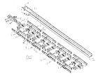
- a skate device 1 having an upper, as viewed, load bearing part 2 and a train of bogey devices 3, each of which is linked to an adjacent bogey device by links 4, 4'.
- Each skate device 3 has in the embodiment of Figs. 1 to 4, four bogey devices each with four rollers 5, making 16 in all, and in Figs. 5 and 6 each bogey device 3 has two rollers 5, making 8 in all.
- skate device 1 has associated with each bogey device 3 a ramp roller 6 and a fixed ramp 7 secured to the underside of the load bearing part 2.
- the skate device includes spacers 10, and side plates 11 which have an S-shaped track for receiving a pin of the load bearing surface 2 to provide a smooth rising and lowering of the load bearing surface.
- the skate device runs in a channel-shape track is usually of aluminium, but could be of other material, such as steel. Whatever the material, in order to avoid tilting or canting of the skate device, and hence jamming in the track, there is carried by the skate device guide means in the form of laterally extending horizontal bearings or rollers 14 which engage the side walls of the track 13 and thus correspond to the internal width thereof to keep the skate device 1 centred in the track so that it runs substantially parallel to the track.
- the horizontal bearings 14 ensure that, apart from themselves, the only items in contact with the track are the rollers 5, which means that the skate devices 1 as a whole cannot damage the track 13. Also, the bearings 14, not being part of the bogey device train, remain in the same vertical position when the skate device is raised and lowered, so that the track is protected when the skate device is raised and lowered because the skate device 1 remains centred in the track 13 by the bearings 14.
- bearings 14 there are two bearings 14 at the fore end F and two bearings 14 at the aft end A of each skate device.
- the bearings 14 are mounted in a block 21 at each end of the skate device.
- abutment 15 in the form of a projection extending outwardly of the link 4, 4', it being understood that both opposite links carry such an abutment although only that on link 4 is visible.
- the projections 15 are the free ends of a rod 16 passing through opposite holes 17 in the links 4 and 4'.
- a rod or lever for actuating the operating mechanism 8, 9 can, on further rotation translate that movement via the bell crank lever 8 and the wish-bone link 9 to longitudinal movement of the bogey device train for raising or lowering via the ramp rollers 6 and ramp 7.
- a skate device always runs in a centred manner in the track, parallel to the tracks, whereby the load may be transported in one go without having to be rearranged now and again.
- An additional advantage is that the only contact between the skate device and the track is through the rollers. This means that the skate device cannot damage the track.
Landscapes
- Engineering & Computer Science (AREA)
- Mechanical Engineering (AREA)
- Aviation & Aerospace Engineering (AREA)
- Chemical & Material Sciences (AREA)
- Combustion & Propulsion (AREA)
- Transportation (AREA)
- Lift-Guide Devices, And Elevator Ropes And Cables (AREA)
- Fittings On The Vehicle Exterior For Carrying Loads, And Devices For Holding Or Mounting Articles (AREA)
- Bridges Or Land Bridges (AREA)
Applications Claiming Priority (2)
| Application Number | Priority Date | Filing Date | Title |
|---|---|---|---|
| DE20005022U | 2000-03-17 | ||
| DE20005022U DE20005022U1 (de) | 2000-03-17 | 2000-03-17 | Führungskonstruktion für Palettenroller in Laufschienen |
Publications (2)
| Publication Number | Publication Date |
|---|---|
| EP1136402A2 true EP1136402A2 (fr) | 2001-09-26 |
| EP1136402A3 EP1136402A3 (fr) | 2004-06-09 |
Family
ID=7938969
Family Applications (1)
| Application Number | Title | Priority Date | Filing Date |
|---|---|---|---|
| EP01302333A Withdrawn EP1136402A3 (fr) | 2000-03-17 | 2001-03-14 | Dispositif pour la manutention d'une charge |
Country Status (2)
| Country | Link |
|---|---|
| EP (1) | EP1136402A3 (fr) |
| DE (1) | DE20005022U1 (fr) |
Cited By (3)
| Publication number | Priority date | Publication date | Assignee | Title |
|---|---|---|---|---|
| JP2015057337A (ja) * | 2013-08-12 | 2015-03-26 | アンクラジャパン株式会社 | 積荷移動台車 |
| JP2016064753A (ja) * | 2014-09-25 | 2016-04-28 | オールセーフ株式会社 | 積荷移動台車 |
| WO2021049713A1 (fr) * | 2019-09-10 | 2021-03-18 | 박영수 | Structure de transport de cargaison |
Families Citing this family (3)
| Publication number | Priority date | Publication date | Assignee | Title |
|---|---|---|---|---|
| GB0109192D0 (en) * | 2001-04-12 | 2001-05-30 | Blackrock Engineering Ltd | Improvements in and relating to load handling skates |
| DE202008012129U1 (de) * | 2008-09-11 | 2010-02-11 | Centa-Antriebe Kirschey Gmbh | Kupplungsanordnung mit zwei axial hintereinander angeordneten Kupplungselementen |
| DE102012223956A1 (de) * | 2012-12-20 | 2014-06-26 | Burg Silvergreen Gmbh | Einlegeteil für eine Führungsmulde |
Family Cites Families (3)
| Publication number | Priority date | Publication date | Assignee | Title |
|---|---|---|---|---|
| MX159453A (es) * | 1983-07-30 | 1989-06-09 | Joloda Loading Systems Ltd | Un trole para manejar carga |
| US4979863A (en) * | 1989-01-10 | 1990-12-25 | Kavieff Shelden M | Apparatus for handling a group of unit loads |
| GB2340819A (en) * | 1998-08-26 | 2000-03-01 | Nippon Light Metal Co | Low lift truck |
-
2000
- 2000-03-17 DE DE20005022U patent/DE20005022U1/de not_active Expired - Lifetime
-
2001
- 2001-03-14 EP EP01302333A patent/EP1136402A3/fr not_active Withdrawn
Cited By (4)
| Publication number | Priority date | Publication date | Assignee | Title |
|---|---|---|---|---|
| JP2015057337A (ja) * | 2013-08-12 | 2015-03-26 | アンクラジャパン株式会社 | 積荷移動台車 |
| JP2016064753A (ja) * | 2014-09-25 | 2016-04-28 | オールセーフ株式会社 | 積荷移動台車 |
| WO2021049713A1 (fr) * | 2019-09-10 | 2021-03-18 | 박영수 | Structure de transport de cargaison |
| CN112789230A (zh) * | 2019-09-10 | 2021-05-11 | 朴英洙 | 货物移送用结构体 |
Also Published As
| Publication number | Publication date |
|---|---|
| EP1136402A3 (fr) | 2004-06-09 |
| DE20005022U1 (de) | 2001-02-15 |
Similar Documents
| Publication | Publication Date | Title |
|---|---|---|
| US2788751A (en) | Bridge for piggyback flat cars | |
| JP3302428B2 (ja) | 産業用リーチ形フォークリフトトラック | |
| US4089399A (en) | Mechanical handling apparatus | |
| CN101678833B (zh) | 利用台车的搬运装置 | |
| JPH01502897A (ja) | 運搬車 | |
| RU2356767C2 (ru) | Железнодорожный грузовой вагон | |
| CN101486366B (zh) | 利用滑动载台的搬运装置 | |
| EP1136402A2 (fr) | Dispositif pour la manutention d'une charge | |
| US4715769A (en) | Rail supported articulated climbing dolly | |
| US2204667A (en) | Transportation means | |
| US10392204B2 (en) | Equipment for moving a pallet | |
| JP2019137512A (ja) | 台車利用の搬送設備 | |
| US2627959A (en) | Material handling mechanism | |
| KR100326090B1 (ko) | 하물취급트롤리 | |
| US5183369A (en) | Access and support apparatus for loading and unloading gondola cars | |
| US4841883A (en) | Shiftable truck bed | |
| JP6853224B2 (ja) | 運搬用台車 | |
| JP4538819B2 (ja) | 摩擦駆動搬送装置 | |
| US3064836A (en) | Load handling device | |
| US2908024A (en) | Adjustable dock ramp | |
| EP1249364B1 (fr) | Améliorations relatives à un chariot porte-charge | |
| JP6336366B2 (ja) | 積荷移動台車 | |
| US1993481A (en) | Transport equipment | |
| JP2000135946A (ja) | 貨物運搬トロリ― | |
| JP4556168B2 (ja) | 車輌運搬車 |
Legal Events
| Date | Code | Title | Description |
|---|---|---|---|
| PUAI | Public reference made under article 153(3) epc to a published international application that has entered the european phase |
Free format text: ORIGINAL CODE: 0009012 |
|
| AK | Designated contracting states |
Kind code of ref document: A2 Designated state(s): AT BE CH CY DE DK ES FI FR GB GR IE IT LI LU MC NL PT SE TR |
|
| AX | Request for extension of the european patent |
Free format text: AL;LT;LV;MK;RO;SI |
|
| PUAL | Search report despatched |
Free format text: ORIGINAL CODE: 0009013 |
|
| AK | Designated contracting states |
Kind code of ref document: A3 Designated state(s): AT BE CH CY DE DK ES FI FR GB GR IE IT LI LU MC NL PT SE TR |
|
| AX | Request for extension of the european patent |
Extension state: AL LT LV MK RO SI |
|
| RIC1 | Information provided on ipc code assigned before grant |
Ipc: 7B 62B 3/06 B Ipc: 7B 65G 67/20 A |
|
| AKX | Designation fees paid | ||
| STAA | Information on the status of an ep patent application or granted ep patent |
Free format text: STATUS: THE APPLICATION IS DEEMED TO BE WITHDRAWN |
|
| REG | Reference to a national code |
Ref country code: DE Ref legal event code: 8566 |
|
| 18D | Application deemed to be withdrawn |
Effective date: 20041001 |