EP1136416A1 - AnscluBvorrichtung - Google Patents
AnscluBvorrichtung Download PDFInfo
- Publication number
- EP1136416A1 EP1136416A1 EP01250082A EP01250082A EP1136416A1 EP 1136416 A1 EP1136416 A1 EP 1136416A1 EP 01250082 A EP01250082 A EP 01250082A EP 01250082 A EP01250082 A EP 01250082A EP 1136416 A1 EP1136416 A1 EP 1136416A1
- Authority
- EP
- European Patent Office
- Prior art keywords
- socket
- connecting element
- fastening element
- fastening
- spring ring
- Prior art date
- Legal status (The legal status is an assumption and is not a legal conclusion. Google has not performed a legal analysis and makes no representation as to the accuracy of the status listed.)
- Granted
Links
- TVEXGJYMHHTVKP-UHFFFAOYSA-N 6-oxabicyclo[3.2.1]oct-3-en-7-one Chemical compound C1C2C(=O)OC1C=CC2 TVEXGJYMHHTVKP-UHFFFAOYSA-N 0.000 description 1
- 230000002411 adverse Effects 0.000 description 1
Images
Classifications
-
- B—PERFORMING OPERATIONS; TRANSPORTING
- B66—HOISTING; LIFTING; HAULING
- B66C—CRANES; LOAD-ENGAGING ELEMENTS OR DEVICES FOR CRANES, CAPSTANS, WINCHES, OR TACKLES
- B66C1/00—Load-engaging elements or devices attached to lifting or lowering gear of cranes or adapted for connection therewith for transmitting lifting forces to articles or groups of articles
- B66C1/10—Load-engaging elements or devices attached to lifting or lowering gear of cranes or adapted for connection therewith for transmitting lifting forces to articles or groups of articles by mechanical means
- B66C1/62—Load-engaging elements or devices attached to lifting or lowering gear of cranes or adapted for connection therewith for transmitting lifting forces to articles or groups of articles by mechanical means comprising article-engaging members of a shape complementary to that of the articles to be handled
- B66C1/66—Load-engaging elements or devices attached to lifting or lowering gear of cranes or adapted for connection therewith for transmitting lifting forces to articles or groups of articles by mechanical means comprising article-engaging members of a shape complementary to that of the articles to be handled for engaging holes, recesses, or abutments on articles specially provided for facilitating handling thereof
Definitions
- the invention relates to a connecting device for fastening of sling or lashing equipment to be transported or objects to be lashed with one their attachment to the respective object, from a screw formed fastener, with a Connection element for the sling or lashing and with the fastener with the connector connecting, rotatable about the longitudinal axis of the fastener on this mounted connecting element, the Connection element is pivotable about a pivot axis, the runs perpendicular to the longitudinal axis of the fastening element, and wherein between the fastener and the Connecting element a the fastener with little Game enclosing socket is arranged.
- a device is known from DE 86 01 343 U1 above type, in which the connecting element with the help one of a retaining bolt loosely guided in the socket formed fastener on the respective object is attachable.
- the known device can do so not fully satisfy as their user a retaining bolt sufficient load capacity at will by a Can replace threaded screw, its load capacity is not meets the prescribed requirements.
- the invention the task is based on the easy exchange possibility resulting dangers largely eliminate without replacing the fastener excluded with special aids.
- This task is achieved in that the two with the Retaining flanges securing the connecting element for the connector provided on their socket Inner wall with a perpendicular to the longitudinal axis of the socket oriented, flat side walls Locking groove for a spring ring with a circular cross-section is equipped that the fastening element forming the a cylindrical section in the area of the bushing having screw in the area of this section with a Ring groove is provided to accommodate the spring washer when inserting the fastener into the socket serves, and that the depth of the flat locking groove at least equal to one fifth and at most equal to one third of the Diameter of the cross section of the spring washer.
- the device according to the invention has the advantage that all their parts form a unit.
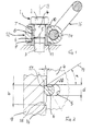
- Fig. 1, 1 is a high load-bearing capacity of a special screw formed fastener that between a Screw head 2 and a threaded section 3 a cylindrical Section 4 has an annular groove 5 into which a cylindrical cross section with a diameter d having spring ring 6 when inserting the fastener 1 in the cylindrical bore 7 one of a upper part 8 and a lower part 9 existing socket can immerse. Both parts 8 and 9 of the socket instruct their outer ends each have a retaining flange 10 or 11 on.
- the locking groove 16 has in one Distance b from each other, perpendicular to the longitudinal axis 13 of the fastener 1 extending side walls 17, 18, the height of which corresponds to the depth t of the locking groove 16.
- the dimensions of the locking groove 16 and the spring ring 12 are coordinated so that the fastener 1 only with considerable effort from the socket 8, 9 can be removed.
- the depth t of the locking groove should be Achievement of this goal at least a fifth and at most one third of the diameter d of the spring ring 12 be.
- a solution has proven to be special Proven useful, in which the tangent 19 to the circumference the spring washer 12 at the point where the edge 20 at one on the fastener 1 in FIG. 1 after force acting above, with respect to the longitudinal axis 13 of the fastening element 1 has an angle ⁇ of approximately Occupies 30 °.
Landscapes
- Engineering & Computer Science (AREA)
- Mechanical Engineering (AREA)
- Bolts, Nuts, And Washers (AREA)
- Clamps And Clips (AREA)
- Pivots And Pivotal Connections (AREA)
- Flanged Joints, Insulating Joints, And Other Joints (AREA)
- Connection Of Plates (AREA)
Abstract
Description
- Fig. 1
- einen Schnitt durch eine besonders vorteilhafte Vorrichtung und
- Fig. 2
- eine Einzelheit der Vorrichtung gemäß Fig. 1.
Claims (4)
- Anschlußvorrichtung zum Befestigen von Anschlag- oder Verzurrmitteln an zu transportierenden oder zu verzurrenden Gegenständen mit einem zu ihrer Befestigung am jeweiligen Gegenstand dienenden, von einer Schraube gebildeten Befestigungselement, mit einem Anschlußelement für das Anschlag- oder Verzurrmittel und mit einem das Befestigungselement mit dem Anschlußelement verbindenden, drehbar um die Längsachse des Befestigungselements an diesem gelagerten Verbindungselement, wobei das Anschlußelement um eine Schwenkachse schwenkbar ist, die senkrecht zur Längsachse des Befestigungselements verläuft, und wobei zwischen dem Befestigungselement und dem Verbindungselement eine das Befestigungselement mit geringem Spiel umschließenden Buchse angeordnet ist, dadurch gekennzeichnet, daß die mit zwei die Drehbarkeit des Verbindungselements (12) sichernden Halteflanschen (10, 11) für das Verbindungselement (12) versehene Buchse (8, 9) an ihrer Innenwand mit einer senkrecht zur Längsachse (13) der Buchse (8, 9) orientierte Seitenwände (17, 18) aufweisenden, umlaufenden flachen Rastnut (16) für einen Federring (6) mit kreisrundem Querschnitt ausgestattet ist, daß die das Befestigungselement (1) bildende, im Bereich der Buchse (8, 9) einen zylindrischen Abschnitt (4) aufweisende Schraube im Bereich dieses Abschnitts (4) mit einer Ringnut (5) versehen ist, die zur Aufnahme des Federrings (6) beim Einführen des Befestigungselements (1) in die Buchse (8, 9) dient, und daß die Tiefe (t) der flachen Rastnut (16) mindestens gleich einem Fünftel und maximal gleich einem Drittel des Durchmessers (d) des Querschnitts des Federrings (12) ist.
- Anschlußvorrichtung nach Anspruch 1, dadurch gekennzeichnet, daß die Breite (b) der Rastnut (16) an der Innenwand der Buchse (8, 9) mindestens gleich dem 1,5fachen Durchmesser (d) des Querschnitts des Federrings (6) ist.
- Anschlußvorrichtung nach Anspruch 1 oder 2, dadurch gekennzeichnet, daß die Buchse (8, 9) aus einem oberen Teil (8) und einem unteren Teil (9) besteht und daß die Rastnut (16) im unteren Teil (9) der zweiteiligen Buchse (8, 9) angeordnet ist.
- Anschlußvorrichtung nach einem der Ansprüche 1 bis 3, dadurch gekennzeichnet, daß die Tangente (19) an den Umfang des Federrings (6) an dessen Berührungspunkt mit der oberen Kante (20) der Rastnut (16) gegenüber der Längsachse (13) des Befestigungselements (1) einen Winkel (α) von etwa 30° einnimmt.
Applications Claiming Priority (2)
| Application Number | Priority Date | Filing Date | Title |
|---|---|---|---|
| DE10013845A DE10013845C2 (de) | 2000-03-15 | 2000-03-15 | Anschlußvorrichtung |
| DE10013845 | 2000-03-15 |
Publications (2)
| Publication Number | Publication Date |
|---|---|
| EP1136416A1 true EP1136416A1 (de) | 2001-09-26 |
| EP1136416B1 EP1136416B1 (de) | 2004-02-18 |
Family
ID=7635676
Family Applications (1)
| Application Number | Title | Priority Date | Filing Date |
|---|---|---|---|
| EP01250082A Expired - Lifetime EP1136416B1 (de) | 2000-03-15 | 2001-03-13 | Anschlussvorrichtung |
Country Status (3)
| Country | Link |
|---|---|
| EP (1) | EP1136416B1 (de) |
| AT (1) | ATE259760T1 (de) |
| DE (1) | DE10013845C2 (de) |
Cited By (3)
| Publication number | Priority date | Publication date | Assignee | Title |
|---|---|---|---|---|
| FR2911592A1 (fr) * | 2007-01-23 | 2008-07-25 | Forges De L Eminee Sa | Anneau de levage pour la prise de charges lourdes |
| EP1961689A1 (de) * | 2007-02-22 | 2008-08-27 | Stamperia Carcano Giuseppe S.p.A. | Befestigungsvorrichtung, Bauteil, Satz und für die Herstellung der Vorrichtung angepasstes Verfahren |
| CN103466433A (zh) * | 2013-09-09 | 2013-12-25 | 中达电机股份有限公司 | 万向吊攀 |
Families Citing this family (3)
| Publication number | Priority date | Publication date | Assignee | Title |
|---|---|---|---|---|
| DE10164598B4 (de) * | 2001-12-21 | 2006-12-14 | Rud-Kettenfabrik Rieger & Dietz Gmbh U. Co. | Anschlussvorrichtung zum Anschließen von Anschlag- oder Verzurrmitteln |
| DE102010032571A1 (de) | 2010-07-28 | 2012-02-02 | Thiele Gmbh & Co. Kg | Flacher Verzurrpunkt |
| DE102013205723A1 (de) | 2013-03-28 | 2014-10-02 | Rud Ketten Rieger & Dietz Gmbh U. Co. Kg | Kugelgelagerter Anschlagpunkt |
Citations (3)
| Publication number | Priority date | Publication date | Assignee | Title |
|---|---|---|---|---|
| DE8601343U1 (de) * | 1986-01-21 | 1986-04-03 | Thiele GmbH & Co. KG, 58640 Iserlohn | Drehbarer Transportring |
| EP0365430A1 (de) * | 1988-10-21 | 1990-04-25 | Marc Lecourt | Hebering für das seitliche Fassen von schweren Lasten |
| US5248176A (en) * | 1989-03-15 | 1993-09-28 | Lars Fredriksson | Swivel coupling device |
Family Cites Families (3)
| Publication number | Priority date | Publication date | Assignee | Title |
|---|---|---|---|---|
| DE803203C (de) * | 1949-10-18 | 1951-03-01 | Ringfeder Gmbh | Sicherung eines Schraubenverbandes |
| DE2620142C3 (de) * | 1976-05-07 | 1982-05-27 | Ford-Werke AG, 5000 Köln | Runddrahtsprengring |
| GB2216946B (en) * | 1988-03-30 | 1992-05-20 | Aeroquip Corp | Deformable ring locking mechanism |
-
2000
- 2000-03-15 DE DE10013845A patent/DE10013845C2/de not_active Expired - Lifetime
-
2001
- 2001-03-13 EP EP01250082A patent/EP1136416B1/de not_active Expired - Lifetime
- 2001-03-13 AT AT01250082T patent/ATE259760T1/de active
Patent Citations (3)
| Publication number | Priority date | Publication date | Assignee | Title |
|---|---|---|---|---|
| DE8601343U1 (de) * | 1986-01-21 | 1986-04-03 | Thiele GmbH & Co. KG, 58640 Iserlohn | Drehbarer Transportring |
| EP0365430A1 (de) * | 1988-10-21 | 1990-04-25 | Marc Lecourt | Hebering für das seitliche Fassen von schweren Lasten |
| US5248176A (en) * | 1989-03-15 | 1993-09-28 | Lars Fredriksson | Swivel coupling device |
Cited By (3)
| Publication number | Priority date | Publication date | Assignee | Title |
|---|---|---|---|---|
| FR2911592A1 (fr) * | 2007-01-23 | 2008-07-25 | Forges De L Eminee Sa | Anneau de levage pour la prise de charges lourdes |
| EP1961689A1 (de) * | 2007-02-22 | 2008-08-27 | Stamperia Carcano Giuseppe S.p.A. | Befestigungsvorrichtung, Bauteil, Satz und für die Herstellung der Vorrichtung angepasstes Verfahren |
| CN103466433A (zh) * | 2013-09-09 | 2013-12-25 | 中达电机股份有限公司 | 万向吊攀 |
Also Published As
| Publication number | Publication date |
|---|---|
| DE10013845A1 (de) | 2001-09-27 |
| EP1136416B1 (de) | 2004-02-18 |
| DE10013845C2 (de) | 2003-04-24 |
| ATE259760T1 (de) | 2004-03-15 |
Similar Documents
| Publication | Publication Date | Title |
|---|---|---|
| DE10200670B4 (de) | Batterie-Befestigungsstruktur für ein Fahrzeug | |
| EP0654611B1 (de) | Ringschraube | |
| DE3140878C2 (de) | ||
| DE2642227B1 (de) | Klemmelement | |
| DE3128169C2 (de) | Abnehmbarer Tragegriff | |
| DE2614961C3 (de) | Karabinerhaken, insbesondere zum Transport von schweren Außenlasten an Hubschraubern | |
| EP1136416A1 (de) | AnscluBvorrichtung | |
| DE1755529C3 (de) | Verbindungsglied für Reifenketten | |
| DE6750366U (de) | Containerverriegelung | |
| DE2425386A1 (de) | Schliessvorrichtung mit einem in ein schliessgehaeuse einsteckbaren und dort verriegelbaren bolzen | |
| DE102009013197B4 (de) | Anschlagelement und Kombination aus einem Anschlagelement und einem Befestigungsmittel | |
| EP0583580A2 (de) | Gabelgelenk | |
| AT397239B (de) | Schienenbefestigung | |
| DE2046344C3 (de) | Vorrichtung zur Schnellbefestigung eines elektrischen Schaltgerätes | |
| DE2833815A1 (de) | Klammerschrauben-verbindungselement | |
| EP1580073B1 (de) | Verriegelungsanordnung zur Festlegung von Containern auf Lastfahrzeugen | |
| DE2643264B2 (de) | Haltevorrichtung für die Hobelkette an Kohlenhobeln | |
| DE19932744C2 (de) | Federelement zur lösbaren Verbindung eines Gabelkopfs mit einem Lagerzapfen | |
| DE20005157U1 (de) | Anschlußvorrichtung | |
| AT501661B1 (de) | Vorrichtung zur befestigung von freizeitgeräten | |
| DE19824221C1 (de) | Hakeneinrichtung für Fahrzeuge, insbesondere Lastkraftwagen | |
| EP0931945B1 (de) | Nutstein mit Formfeder | |
| DE2804735C3 (de) | Endbeschlag für Lasthebe- und/oder Verzurrbänder | |
| DE2829193C2 (de) | Verriegelungsvorrichtung für ein Ballastgewicht eines Schleppers | |
| EP0104135A2 (de) | Anordnung zum Verbinden von Bauteilen sowie Spann- und/oder Kontrollvorrichtung von Hebe- und/oder Verzurranordnungen mit Gurten |
Legal Events
| Date | Code | Title | Description |
|---|---|---|---|
| PUAI | Public reference made under article 153(3) epc to a published international application that has entered the european phase |
Free format text: ORIGINAL CODE: 0009012 |
|
| AK | Designated contracting states |
Kind code of ref document: A1 Designated state(s): AT FR GB IT SE Kind code of ref document: A1 Designated state(s): AT BE CH CY DE DK ES FI FR GB GR IE IT LI LU MC NL PT SE TR |
|
| AX | Request for extension of the european patent |
Free format text: AL;LT;LV;MK;RO;SI |
|
| 17P | Request for examination filed |
Effective date: 20020311 |
|
| AKX | Designation fees paid |
Free format text: AT FR GB IT SE |
|
| REG | Reference to a national code |
Ref country code: DE Ref legal event code: 8566 |
|
| GRAP | Despatch of communication of intention to grant a patent |
Free format text: ORIGINAL CODE: EPIDOSNIGR1 |
|
| GRAS | Grant fee paid |
Free format text: ORIGINAL CODE: EPIDOSNIGR3 |
|
| GRAA | (expected) grant |
Free format text: ORIGINAL CODE: 0009210 |
|
| AK | Designated contracting states |
Kind code of ref document: B1 Designated state(s): AT FR GB IT SE |
|
| REG | Reference to a national code |
Ref country code: GB Ref legal event code: FG4D Free format text: NOT ENGLISH |
|
| GBT | Gb: translation of ep patent filed (gb section 77(6)(a)/1977) |
Effective date: 20040415 |
|
| ET | Fr: translation filed | ||
| PLBE | No opposition filed within time limit |
Free format text: ORIGINAL CODE: 0009261 |
|
| STAA | Information on the status of an ep patent application or granted ep patent |
Free format text: STATUS: NO OPPOSITION FILED WITHIN TIME LIMIT |
|
| 26N | No opposition filed |
Effective date: 20041119 |
|
| REG | Reference to a national code |
Ref country code: FR Ref legal event code: CD |
|
| REG | Reference to a national code |
Ref country code: FR Ref legal event code: PLFP Year of fee payment: 15 |
|
| REG | Reference to a national code |
Ref country code: FR Ref legal event code: PLFP Year of fee payment: 16 |
|
| REG | Reference to a national code |
Ref country code: FR Ref legal event code: PLFP Year of fee payment: 17 |
|
| REG | Reference to a national code |
Ref country code: FR Ref legal event code: PLFP Year of fee payment: 18 |
|
| PGFP | Annual fee paid to national office [announced via postgrant information from national office to epo] |
Ref country code: FR Payment date: 20200725 Year of fee payment: 20 Ref country code: GB Payment date: 20200725 Year of fee payment: 20 |
|
| PGFP | Annual fee paid to national office [announced via postgrant information from national office to epo] |
Ref country code: AT Payment date: 20200728 Year of fee payment: 20 Ref country code: SE Payment date: 20200730 Year of fee payment: 20 Ref country code: IT Payment date: 20200731 Year of fee payment: 20 |
|
| REG | Reference to a national code |
Ref country code: GB Ref legal event code: PE20 Expiry date: 20210312 |
|
| PG25 | Lapsed in a contracting state [announced via postgrant information from national office to epo] |
Ref country code: GB Free format text: LAPSE BECAUSE OF EXPIRATION OF PROTECTION Effective date: 20210312 |
|
| REG | Reference to a national code |
Ref country code: AT Ref legal event code: MK07 Ref document number: 259760 Country of ref document: AT Kind code of ref document: T Effective date: 20210313 |
|
| REG | Reference to a national code |
Ref country code: SE Ref legal event code: EUG |