EP1136423B1 - Einrichtung zur Begrenzung der oberen Drehzahl eines Balancier-Hebezeugs - Google Patents
Einrichtung zur Begrenzung der oberen Drehzahl eines Balancier-Hebezeugs Download PDFInfo
- Publication number
- EP1136423B1 EP1136423B1 EP01250086A EP01250086A EP1136423B1 EP 1136423 B1 EP1136423 B1 EP 1136423B1 EP 01250086 A EP01250086 A EP 01250086A EP 01250086 A EP01250086 A EP 01250086A EP 1136423 B1 EP1136423 B1 EP 1136423B1
- Authority
- EP
- European Patent Office
- Prior art keywords
- hoist
- housing
- threaded spindle
- cone
- stop element
- Prior art date
- Legal status (The legal status is an assumption and is not a legal conclusion. Google has not performed a legal analysis and makes no representation as to the accuracy of the status listed.)
- Expired - Lifetime
Links
- 230000008719 thickening Effects 0.000 claims description 5
- 210000003746 feather Anatomy 0.000 description 3
- 238000011990 functional testing Methods 0.000 description 3
- 239000000725 suspension Substances 0.000 description 2
- 239000000853 adhesive Substances 0.000 description 1
- 230000001070 adhesive effect Effects 0.000 description 1
- 238000010276 construction Methods 0.000 description 1
- 230000002950 deficient Effects 0.000 description 1
- 230000014759 maintenance of location Effects 0.000 description 1
- 230000036316 preload Effects 0.000 description 1
- 238000007789 sealing Methods 0.000 description 1
- 230000035939 shock Effects 0.000 description 1
- 230000009466 transformation Effects 0.000 description 1
Images

Classifications
-
- B—PERFORMING OPERATIONS; TRANSPORTING
- B66—HOISTING; LIFTING; HAULING
- B66D—CAPSTANS; WINCHES; TACKLES, e.g. PULLEY BLOCKS; HOISTS
- B66D3/00—Portable or mobile lifting or hauling appliances
- B66D3/18—Power-operated hoists
-
- B—PERFORMING OPERATIONS; TRANSPORTING
- B66—HOISTING; LIFTING; HAULING
- B66D—CAPSTANS; WINCHES; TACKLES, e.g. PULLEY BLOCKS; HOISTS
- B66D5/00—Braking or detent devices characterised by application to lifting or hoisting gear, e.g. for controlling the lowering of loads
- B66D5/02—Crane, lift hoist, or winch brakes operating on drums, barrels, or ropes
- B66D5/04—Crane, lift hoist, or winch brakes operating on drums, barrels, or ropes actuated by centrifugal force
-
- B—PERFORMING OPERATIONS; TRANSPORTING
- B66—HOISTING; LIFTING; HAULING
- B66D—CAPSTANS; WINCHES; TACKLES, e.g. PULLEY BLOCKS; HOISTS
- B66D2700/00—Capstans, winches or hoists
- B66D2700/02—Hoists or accessories for hoists
- B66D2700/023—Hoists
-
- B—PERFORMING OPERATIONS; TRANSPORTING
- B66—HOISTING; LIFTING; HAULING
- B66D—CAPSTANS; WINCHES; TACKLES, e.g. PULLEY BLOCKS; HOISTS
- B66D2700/00—Capstans, winches or hoists
- B66D2700/03—Mechanisms with latches or braking devices in general for capstans, hoists or similar devices as well as braking devices actuated electrically or by fluid under pressure
Definitions
- the invention relates to a Balancing hoist according to the preamble of claim 1.
- Balancing hoists are known, in particular from the patent publications US 5,553,832, US 5,522,581, US 5,556,077 and US 5,439,200.
- these Hoists the axial movement of a hollow piston in a rotary motion of a Rope or chain storage drum or a chain nut converted.
- These Transformation is done by means of a ball screw.
- either the spindle rotatably in a housing and the mother with the Drum longitudinally displaceable on the spindle at 5.553.832, 5.522.581, 5.556.077 Fig. 11 u. 5,439,200 Fig.
- the object of the invention is a balancing - hoist with a speed limiting device specify in the after a simple Functional test and a simple replacement of defective components is possible, without that the hoist previously released from the suspension and then consuming must be dismantled.
- the solution provides that one end of the threaded spindle in one from the outside accessible housing chamber protrudes, which is preferably closed like a lid, and that at the end of the spindle a device for limiting the upper speed of the Spindle is arranged.
- This limiting device is frictionally engaged with the spindle connected.
- the one or more stop elements are fixed inside the housing arranged.
- the idea of the invention is therefore to have the device in one separate housing chamber, which after removing a lid, the Housing chamber dust-tight closes, easily accessible from the outside. In these Housing chamber protrudes into the threaded spindle, which with the pivot axes of the Brake pawls is connected.
- the or each stop element is inside in this solution formed on the housing, for example, as a thickening of the housing wall on the Inside.
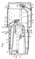
- Fig. 1 shows a Balancier hoist with a housing 10, which - with reference to FIG. 1 - right half is designed as a hollow cylinder 11.
- the hollow cylinder 11 is through a Cover 12 sealed with a seal 13 dustproof.
- a cylindrical piston 14 In the longitudinal direction of Hollow cylinder 11 is a cylindrical piston 14 with a sealing ring 15 slidably arranged.
- the piston 14 is located with a thrust bearing 16 at a face of a Cable drum 17, which via a feather key 18 with the right end of a Threaded spindle 19 is torsionally and rigidly connected.
- the cable drum 17 has on their outer circumference grooves 20 for receiving a wire rope 21.
- Die Threaded spindle 19 is rotatably mounted in a ball nut 19a which rotatably is arranged in the housing 10.
- the piston 14, the cable drum 17 and the threaded spindle 19 are shown in Fig. 1 in the upper half of the picture in her left and in the lower half in her right End position shown.
- the wire rope 21 on the Cable drum 17 In the left end position, the wire rope 21 on the Cable drum 17 fully wound (highest load position) and in the right End position completely unwound (lowest load position).
- the cable drum 17 expiring wire rope 21 exits through an opening 21a of the housing 10 and carries at its free end a payload, not shown.
- the threaded spindle 19 protrudes with their reference to FIG. 1 left end in one Housing chamber 22 which is closed dustproof with a lid 22a.
- Figs. 2 and 3 show the device for limiting the upper speed at removed cover 22a in a schematic representation (Fig. 3 as Cross section through the device of FIG. 2 along the line of sight III - III).
- a plate-shaped outer cone 23 attached to the outer ring two each about a pin-like pivot axis 25 pivotable pawls 24th are provided.
- the pawls 24 are biased by a spring 26 inwards pulled, so at standstill of the threaded spindle 19 in its standby position held.
- the transmissible torque may vary over the size of the Preload can be adjusted with the screw 29.
- the feather key 27a protrudes its left end in a recess of the disc 28, whereby the latter opposite the threaded spindle 19 is held against rotation.
- cam-like thickenings are arranged as a stop element 32, the to the threaded spindle 19 point.
- the functioning of the device is as follows: With increasing speed of the cable drum 17, the pawls 24 are moved about the pivot axes 25 against the retaining force of the springs 26 radially outward. At a limiting rotational speed of the threaded spindle 19 (and thus of the cable drum 17), surfaces 33 arranged on the pawls (contact surfaces) abut against the thickenings 32 and stop the rotational movement of the outer cone 23.
- the pins 30 limit in cooperation with a corresponding arrangement of Openings 31 the swivel angle of the pawls 24. They guarantee that only the Surfaces 33 come into contact with the stop elements 32. It is also achieved that the springs 26 are not overstretched.
Landscapes
- Engineering & Computer Science (AREA)
- Mechanical Engineering (AREA)
- Braking Arrangements (AREA)
- Centrifugal Separators (AREA)
- Load-Engaging Elements For Cranes (AREA)
Description
- Fig. 1
- einen Längsschnitt durch ein Balancier-Hebezeug,
- Fig. 2
- eine Ansicht der Einrichtung zur Begrenzung der Drehzahl,
- Fig. 3
- einen Querschnitt durch die Einrichtung gemäß Fig. 3 entlang der Sichtlinie III - III und
- Fig. 4
- einen Querschnitt gemäß Fig. 3 entlang der Sichtlinie IV - IV.
Bei zunehmender Drehzahl der Seiltrommel 17 werden die Klinken 24 um die Schwenkachsen 25 gegen die Rückhaltekraft der Federn 26 radial nach außen bewegt. Bei einer Grenzdrehzahl der Gewindespindel 19 (und damit der Seiltrommel 17) legen sich an den Klinken 24 angeordnete Flächen 33 (Anlageflächen) an die Verdickungen 32 an und stoppen die Drehbewegung des Außenkonus 23.
- 10
- Gehäuse
- 11
- Hohlzylinder
- 12
- Deckel
- 13
- Dichtung
- 14
- Kolben
- 15
- Dichtring
- 16
- Axiallager
- 17
- Seiltrommel
- 18
- Passfeder
- 19
- Gewindespindel
- 19a
- Kugelumlaufmutter
- 20
- Rille
- 21
- Drahtseil
- 21a
- Öffnung
- 22
- Gehäusekammer
- 22a
- Deckel
- 23
- Außenkonus
- 24
- Klinke
- 25
- Schwenkachse
- 26
- Feder
- 27
- Innenkonus
- 27a
- Passfeder
- 28
- Scheibe
- 29
- Schraube
- 30
- Stift
- 31
- Öffnung
- 32
- Verdickung
- 33
- Anschlagfläche
Claims (7)
- Balancier-Hebezeug mit einer Drehzahlbegrenzungseinrichtung, insbesondere zur Notabbremsung des Hebezeugs, das eine in einem Gehäuse (10) drehgelagerte, mittels eines pneumatisch im Gehäuse (10) längsverschiebbaren Kolbens (14) drehbare und eine Seiltrommel (17) tragende Gewindespindel (19) sowie eine mit dem Gehäuse (10) fest verbundene Spindelmutter aufweist, wobei die auf der Gewindespindel (19) längsverschiebliche Seiltrommel (17) drehfest mit dieser verbunden ist,
mit mindestens einem gegen eine elastische Rückhaltekraft um eine zur Gewindespindel (19) parallele Schwenkachse (25) von einer radial innenliegenden Ruhestellung zu einer außenliegenden Bremsstellung verschwenkbaren Klinke (24), die bei drehender Seiltrommel (17) jeweils in Drehrichtung weist und fliehkraftbeaufschlagt ab einer von der Größe der Rückhaltekraft vorbestimmten Drehzahl mit ihrem freien Ende in die Bremsstellung verschwenkbar ist,
mit zumindest einem feststehenden radial auf Höhe der außenliegenden Bremsstellung angeordneten Stoppelement (32), das mit der in der außenliegenden Bremsstellung befindlichen Klinke (24) zusammenwirkend die Drehbewegung der Seiltrommel (17) bis zu deren Stillstand abbremst,
dadurch gekennzeichnet, dass ein Ende der Gewindespindel (19) in eine von außen zugängliche Gehäusekammer (22) ragt und dort mit der Schwenkachse (25) verbunden ist und dass das oder jedes Stoppelement (32) innen am Gehäuse (10) feststehend angeordnet ist. - Balancier-Hebezeug nach Anspruch 1;
dadurch gekennzeichnet, dass jedes Stoppelement (32) als ins Gehäuse (10) ragende Verdickung an der Gehäusewand ausgebildet ist. - Balancier-Hebezeug nach einem der Ansprüche 1 oder 2,
dadurch gekennzeichnet, dass ein Innenkonus (27) an der Gewindespindel (19) drehfest befestigt ist, auf den ein korrespondierender Außenkonus (23) geschoben ist, und dass die Schwenkachsen (25) am Außenkonus (23) angeordnet sind. - Balancier-Hebezeug nach Anspruch 3,
dadurch gekennzeichnet, dass der Innenkonus (27) gegen den Außenkonus (23) in axialer Richtung verspannt ist. - Balancier-Hebezeug nach Anspruch 4,
dadurch gekennzeichnet, dass der Schwenkwinkel der Klinken (24) begrenzt ist. - Balancier-Hebezeug nach einem der Ansprüche 1 - 5,
dadurch gekennzeichnet, dass jede Klinke 24 eine Vertiefung mit einer Anlagefläche (33) zur definierten Anlage an ein Stoppelement (32) aufweist. - Balancier-Hebezeug nach einem der Ansprüche 1 - 6,
dadurch gekennzeichnet, dass die Längsachsen der Klinken (24) jeweils einen Winkel kleiner 150 Grad mit der Ebene einschließen, in der jeweils die zugehörige Schwenkachse (25) und die Gewindespindelachse liegen.
Applications Claiming Priority (2)
| Application Number | Priority Date | Filing Date | Title |
|---|---|---|---|
| DE10014910 | 2000-03-17 | ||
| DE10014910 | 2000-03-17 |
Publications (2)
| Publication Number | Publication Date |
|---|---|
| EP1136423A1 EP1136423A1 (de) | 2001-09-26 |
| EP1136423B1 true EP1136423B1 (de) | 2005-07-20 |
Family
ID=7636372
Family Applications (1)
| Application Number | Title | Priority Date | Filing Date |
|---|---|---|---|
| EP01250086A Expired - Lifetime EP1136423B1 (de) | 2000-03-17 | 2001-03-14 | Einrichtung zur Begrenzung der oberen Drehzahl eines Balancier-Hebezeugs |
Country Status (5)
| Country | Link |
|---|---|
| US (1) | US6578822B2 (de) |
| EP (1) | EP1136423B1 (de) |
| JP (1) | JP2001316083A (de) |
| KR (1) | KR20010090463A (de) |
| DE (1) | DE50106749D1 (de) |
Families Citing this family (9)
| Publication number | Priority date | Publication date | Assignee | Title |
|---|---|---|---|---|
| KR100402110B1 (ko) * | 2001-09-12 | 2003-10-17 | 주식회사 고려호이스트 | 에어밸런싱 호이스트의 안전장치 |
| DE10344240B4 (de) * | 2003-09-23 | 2007-10-18 | Manfred Josef Wallner | Druckluftbalancer mit Bremse |
| DE10344245B4 (de) | 2003-09-23 | 2006-07-06 | Manfred Josef Wallner | Druckluftbalancer |
| US8118143B2 (en) * | 2007-11-29 | 2012-02-21 | Axel Brandt | Centrifugal emergency brake |
| US8613683B2 (en) | 2009-04-15 | 2013-12-24 | Srinivas R. Bidare | Pneumato-mechanical regenerative power source |
| DE102011103320A1 (de) * | 2011-05-27 | 2012-11-29 | Konecranes Plc | Balancer |
| TWI483888B (zh) * | 2012-11-01 | 2015-05-11 | Hiwin Tech Corp | 具有安全緩降機制的升降裝置 |
| CN103482519B (zh) * | 2013-09-09 | 2016-09-21 | 华南理工大学 | 一种气动葫芦离合制动器 |
| CN114195029A (zh) * | 2021-11-09 | 2022-03-18 | 中建中新建设工程有限公司 | 一种建筑机电设备的辅助安装装置 |
Family Cites Families (9)
| Publication number | Priority date | Publication date | Assignee | Title |
|---|---|---|---|---|
| US2896912A (en) * | 1955-11-15 | 1959-07-28 | Faugier Gabriel | Safety apparatus |
| US3286989A (en) * | 1965-10-19 | 1966-11-22 | Ingersoll Rand Co | Balancing hoist |
| US3526388A (en) * | 1968-06-06 | 1970-09-01 | Ingersoll Rand Co | Balancing hoist |
| US5553832A (en) | 1993-03-12 | 1996-09-10 | Knight Industries, Inc. | Safety device for an air balancing hoist |
| US5439200A (en) | 1993-12-10 | 1995-08-08 | Columbus Mckinnon Corporation | Air lifting and balancing unit |
| US5848781A (en) * | 1994-01-13 | 1998-12-15 | Ingersoll-Rand Company | Balancing hoist braking system |
| US5522581A (en) | 1994-01-13 | 1996-06-04 | Zimmerman International Corp. | Balancing hoist and material handling system |
| US5593138A (en) * | 1995-03-31 | 1997-01-14 | Knight Industries, Inc. | Air balancing hoist combination |
| DE19838674C2 (de) * | 1998-08-20 | 2000-12-14 | Mannesmann Ag | Winde |
-
2001
- 2001-03-13 US US09/804,841 patent/US6578822B2/en not_active Expired - Lifetime
- 2001-03-14 DE DE50106749T patent/DE50106749D1/de not_active Expired - Lifetime
- 2001-03-14 EP EP01250086A patent/EP1136423B1/de not_active Expired - Lifetime
- 2001-03-16 KR KR1020010013598A patent/KR20010090463A/ko not_active Withdrawn
- 2001-03-19 JP JP2001078099A patent/JP2001316083A/ja active Pending
Also Published As
| Publication number | Publication date |
|---|---|
| JP2001316083A (ja) | 2001-11-13 |
| EP1136423A1 (de) | 2001-09-26 |
| US20010022358A1 (en) | 2001-09-20 |
| DE50106749D1 (de) | 2005-08-25 |
| KR20010090463A (ko) | 2001-10-18 |
| US6578822B2 (en) | 2003-06-17 |
Similar Documents
| Publication | Publication Date | Title |
|---|---|---|
| EP1136423B1 (de) | Einrichtung zur Begrenzung der oberen Drehzahl eines Balancier-Hebezeugs | |
| DE102011014357B3 (de) | Kraftschrauber-Überlastsicherung | |
| DE2246454A1 (de) | Anschlag zur begrenzung der axialen relativbewegung zwischen zwei mechanischen teilen | |
| DE2826537A1 (de) | Planetare drahtzufuehreinrichtung | |
| DE10393521T5 (de) | Bremseinrichtung für Gerotor-Motoren | |
| DE19917498A1 (de) | Wälzlager-Drehverbindung | |
| EP1518468B1 (de) | Fördertrommel mit Spanneinrichtung | |
| DE8422260U1 (de) | Innen umgriffene Scheibenbremse, insbesondere für Kraftfahrzeuge | |
| DE3615985A1 (de) | Vorrichtung zum abstoppen einer achse oder dergleichen | |
| DE2822549C2 (de) | Spannvorrichtung | |
| DE3048339A1 (de) | Winkelbewegliche gelenkkupplung | |
| DE3140792C2 (de) | Sicherungsvorrichtung gegen ungewolltes Abrollen von auf Wickelwellen aufgerollten Öffnungsabschlüssen | |
| DE19838674C2 (de) | Winde | |
| DE19920544C2 (de) | Gelenk für ein Werkzeug | |
| DE3013009A1 (de) | Vorrichtung zum antrieb eines kraftfahrzeugspiegels | |
| EP1407846A1 (de) | Werkzeugspanner | |
| EP1861308B1 (de) | Pedal für ein fahrrad | |
| DE2821415A1 (de) | Axialverdichter | |
| DE29723270U1 (de) | Schnellspann-Vorrichtung zur Befestigung von Werkzeugen, insbesondere Kreissägeblättern | |
| DE1171690B (de) | Hebelwerk zum Festhalten von einem durch ein Drehmoment beanspruchten Maschinenteil | |
| DE10344240B4 (de) | Druckluftbalancer mit Bremse | |
| DE2924816A1 (de) | Reibungskupplung | |
| DE2652768C2 (de) | Rotor einer elektrischen Maschine, bei dem die Rotornabe auf der Welle mittels einer für das Nennmoment ausgelegten Reibverbindung befestigt ist | |
| DE1541192C (de) | Zahnärztliches Turbmenhandstuck | |
| AT244386B (de) | Schleppseilgehänge für Seilförderanlagen |
Legal Events
| Date | Code | Title | Description |
|---|---|---|---|
| PUAI | Public reference made under article 153(3) epc to a published international application that has entered the european phase |
Free format text: ORIGINAL CODE: 0009012 |
|
| AK | Designated contracting states |
Kind code of ref document: A1 Designated state(s): AT BE CH CY DE DK ES FI FR GB GR IE IT LI LU MC NL PT SE TR Kind code of ref document: A1 Designated state(s): DE FR GB IT NL SE |
|
| AX | Request for extension of the european patent |
Free format text: AL;LT;LV;MK;RO;SI |
|
| RIN1 | Information on inventor provided before grant (corrected) |
Inventor name: HEUN, JUERGEN Inventor name: WINTER, KLAUS-JUERGEN, DIPL.-ING. (FH) Inventor name: LOEBEL, MARKUS, DIPL.-ING. Inventor name: SPIES, HARALD |
|
| 17P | Request for examination filed |
Effective date: 20020308 |
|
| AKX | Designation fees paid |
Free format text: AT BE CH CY DE DK LI |
|
| RAP1 | Party data changed (applicant data changed or rights of an application transferred) |
Owner name: DEMAG CRANES & COMPONENTS GMBH |
|
| RBV | Designated contracting states (corrected) |
Designated state(s): DE FR GB IT NL SE |
|
| 17Q | First examination report despatched |
Effective date: 20040616 |
|
| GRAP | Despatch of communication of intention to grant a patent |
Free format text: ORIGINAL CODE: EPIDOSNIGR1 |
|
| GRAS | Grant fee paid |
Free format text: ORIGINAL CODE: EPIDOSNIGR3 |
|
| GRAA | (expected) grant |
Free format text: ORIGINAL CODE: 0009210 |
|
| AK | Designated contracting states |
Kind code of ref document: B1 Designated state(s): DE FR GB IT NL SE |
|
| PG25 | Lapsed in a contracting state [announced via postgrant information from national office to epo] |
Ref country code: GB Free format text: LAPSE BECAUSE OF FAILURE TO SUBMIT A TRANSLATION OF THE DESCRIPTION OR TO PAY THE FEE WITHIN THE PRESCRIBED TIME-LIMIT Effective date: 20050720 Ref country code: NL Free format text: LAPSE BECAUSE OF FAILURE TO SUBMIT A TRANSLATION OF THE DESCRIPTION OR TO PAY THE FEE WITHIN THE PRESCRIBED TIME-LIMIT Effective date: 20050720 |
|
| REG | Reference to a national code |
Ref country code: GB Ref legal event code: FG4D Free format text: NOT ENGLISH |
|
| REF | Corresponds to: |
Ref document number: 50106749 Country of ref document: DE Date of ref document: 20050825 Kind code of ref document: P |
|
| PG25 | Lapsed in a contracting state [announced via postgrant information from national office to epo] |
Ref country code: SE Free format text: LAPSE BECAUSE OF FAILURE TO SUBMIT A TRANSLATION OF THE DESCRIPTION OR TO PAY THE FEE WITHIN THE PRESCRIBED TIME-LIMIT Effective date: 20051020 |
|
| NLV1 | Nl: lapsed or annulled due to failure to fulfill the requirements of art. 29p and 29m of the patents act | ||
| GBV | Gb: ep patent (uk) treated as always having been void in accordance with gb section 77(7)/1977 [no translation filed] |
Effective date: 20050720 |
|
| ET | Fr: translation filed | ||
| PLBE | No opposition filed within time limit |
Free format text: ORIGINAL CODE: 0009261 |
|
| STAA | Information on the status of an ep patent application or granted ep patent |
Free format text: STATUS: NO OPPOSITION FILED WITHIN TIME LIMIT |
|
| 26N | No opposition filed |
Effective date: 20060421 |
|
| PG25 | Lapsed in a contracting state [announced via postgrant information from national office to epo] |
Ref country code: IT Free format text: LAPSE BECAUSE OF NON-PAYMENT OF DUE FEES Effective date: 20080314 |
|
| REG | Reference to a national code |
Ref country code: FR Ref legal event code: PLFP Year of fee payment: 15 |
|
| PGFP | Annual fee paid to national office [announced via postgrant information from national office to epo] |
Ref country code: DE Payment date: 20150320 Year of fee payment: 15 |
|
| PGFP | Annual fee paid to national office [announced via postgrant information from national office to epo] |
Ref country code: FR Payment date: 20150319 Year of fee payment: 15 |
|
| PGFP | Annual fee paid to national office [announced via postgrant information from national office to epo] |
Ref country code: IT Payment date: 20150331 Year of fee payment: 15 |
|
| REG | Reference to a national code |
Ref country code: DE Ref legal event code: R119 Ref document number: 50106749 Country of ref document: DE |
|
| REG | Reference to a national code |
Ref country code: FR Ref legal event code: ST Effective date: 20161130 |
|
| PG25 | Lapsed in a contracting state [announced via postgrant information from national office to epo] |
Ref country code: DE Free format text: LAPSE BECAUSE OF NON-PAYMENT OF DUE FEES Effective date: 20161001 Ref country code: FR Free format text: LAPSE BECAUSE OF NON-PAYMENT OF DUE FEES Effective date: 20160331 |
|
| PG25 | Lapsed in a contracting state [announced via postgrant information from national office to epo] |
Ref country code: IT Free format text: LAPSE BECAUSE OF NON-PAYMENT OF DUE FEES Effective date: 20160314 |