EP1136437B1 - Embout de raccord rapide, raccord rapide comprenant un tel embout et système de remplissage d'un réservoir embarqué comprenant un tel raccord - Google Patents
Embout de raccord rapide, raccord rapide comprenant un tel embout et système de remplissage d'un réservoir embarqué comprenant un tel raccord Download PDFInfo
- Publication number
- EP1136437B1 EP1136437B1 EP20010420064 EP01420064A EP1136437B1 EP 1136437 B1 EP1136437 B1 EP 1136437B1 EP 20010420064 EP20010420064 EP 20010420064 EP 01420064 A EP01420064 A EP 01420064A EP 1136437 B1 EP1136437 B1 EP 1136437B1
- Authority
- EP
- European Patent Office
- Prior art keywords
- valve
- piece
- housing
- reservoir
- seat
- Prior art date
- Legal status (The legal status is an assumption and is not a legal conclusion. Google has not performed a legal analysis and makes no representation as to the accuracy of the status listed.)
- Expired - Lifetime
Links
- 230000008878 coupling Effects 0.000 claims description 23
- 238000010168 coupling process Methods 0.000 claims description 23
- 238000005859 coupling reaction Methods 0.000 claims description 23
- 239000007788 liquid Substances 0.000 claims description 14
- 230000000295 complement effect Effects 0.000 claims description 10
- 239000012530 fluid Substances 0.000 claims description 7
- 230000033228 biological regulation Effects 0.000 claims description 3
- 229920001971 elastomer Polymers 0.000 claims description 3
- 239000000806 elastomer Substances 0.000 claims description 3
- 239000000463 material Substances 0.000 claims description 2
- 238000005192 partition Methods 0.000 claims description 2
- 239000000654 additive Substances 0.000 description 10
- 230000000996 additive effect Effects 0.000 description 10
- 230000000694 effects Effects 0.000 description 5
- 208000031968 Cadaver Diseases 0.000 description 4
- 239000000446 fuel Substances 0.000 description 4
- 230000002093 peripheral effect Effects 0.000 description 3
- 230000001105 regulatory effect Effects 0.000 description 3
- 238000004519 manufacturing process Methods 0.000 description 2
- 230000009471 action Effects 0.000 description 1
- 230000003213 activating effect Effects 0.000 description 1
- 239000011324 bead Substances 0.000 description 1
- 238000002485 combustion reaction Methods 0.000 description 1
- 230000006835 compression Effects 0.000 description 1
- 238000007906 compression Methods 0.000 description 1
- 230000001276 controlling effect Effects 0.000 description 1
- 230000007423 decrease Effects 0.000 description 1
- 238000006073 displacement reaction Methods 0.000 description 1
- 239000003344 environmental pollutant Substances 0.000 description 1
- 238000001704 evaporation Methods 0.000 description 1
- 230000008020 evaporation Effects 0.000 description 1
- 239000002816 fuel additive Substances 0.000 description 1
- 238000010438 heat treatment Methods 0.000 description 1
- 238000012423 maintenance Methods 0.000 description 1
- 230000013011 mating Effects 0.000 description 1
- 231100000719 pollutant Toxicity 0.000 description 1
- 230000000644 propagated effect Effects 0.000 description 1
- 239000010802 sludge Substances 0.000 description 1
- 230000007704 transition Effects 0.000 description 1
- 238000009423 ventilation Methods 0.000 description 1
Images


Classifications
-
- B—PERFORMING OPERATIONS; TRANSPORTING
- B67—OPENING, CLOSING OR CLEANING BOTTLES, JARS OR SIMILAR CONTAINERS; LIQUID HANDLING
- B67D—DISPENSING, DELIVERING OR TRANSFERRING LIQUIDS, NOT OTHERWISE PROVIDED FOR
- B67D7/00—Apparatus or devices for transferring liquids from bulk storage containers or reservoirs into vehicles or into portable containers, e.g. for retail sale purposes
- B67D7/06—Details or accessories
- B67D7/42—Filling nozzles
- B67D7/54—Filling nozzles with means for preventing escape of liquid or vapour or for recovering escaped liquid or vapour
Definitions
- the invention relates to a quick coupling end piece, a quick connector comprising such a tip and a system of filling an onboard tank or to embark on a motor vehicle comprising such a coupling.
- Such tips are already known in the state of the art, see by for example US-A-3,171,448.
- the filling of the tanks must be carried out with the greatest care to avoid any risk of pollution by runoff and / or evaporation and this, especially as the additive tank is likely to be filled by the interior of the vehicle interior in a possible area accessible to passengers. So far, filling initial additive tanks is performed on a bench dedicated for this purpose and provided with powerful ventilation means in order to avoid pollution of the work area by vapors of the additive, which can be considered on a string of manufacture but can not be implemented in a concession of a motor vehicle brand. In addition, the current fill mode does not prevent inclusion air bubbles in the product spilled into the tank.
- the invention intends to respond by proposing a quick coupling tip to avoid leaking filling liquids when connecting or disconnection of the fitting while no inclusion of air is generated in the liquid passing through this connection and that the product vapors possibly present in the reservoir are efficiently collected.
- the invention it is possible to fill a tank on a motor vehicle without risk dripping or steam propagation. He is particularly possible to connect two pipes, connected respectively in the lower part and in the upper part auxiliary additive tank for a vehicle fuel two-pipe, respectively the supply of liquid to this reservoir and the collection of the vents from this tank.
- the second and third aforementioned dwellings may be distinct or the choices of realization. In the case where they are distinct, these dwellings are in communication.
- the invention also relates to a second mouthpiece quick coupling adapted to cooperate with the receiving tip as previously described and, more specifically, a coupling tip comprising a flapper, movable inside a housing formed by a body of this mouthpiece, between a first position where it closes and a second position where it releases a first flow path fluid, from or to a first pipe, this valve being able to be controlled by a member of a complementary end piece of the fitting, while the body of the mouthpiece two moving parts relative to each other, a second fluid flow path from or to a second pipe being at least partially defined between these two parts, one of these parts forming an actuating member a valve of the complementary nozzle.
- This coupling end is characterized in that it is integrated in a hand tool provided with a trigger for controlling the relative position of two aforementioned parts of the body.
- the invention also relates to a quick coupling of security for the detachable connection of two pipes twice which comprises at least one tip as previously described.
- Such a connection is easy to handle and allows a efficient connection without risk of leakage between two sets of two pipes.
- the invention finally relates to a filling system of a tank onboard or to embark on a motor vehicle which comprises at least one quick coupling as mentioned above.
- a system makes it possible to envisage filling a safe reservoir of potentially liquid flow pollutant or spread of vapors in the vicinity of a operator, including inside the cockpit of a vehicle or in the lower part of it, during operations of maintenance.
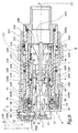
- the quick coupling shown in the figures comprises a male receiving end A intended to be mounted on a motor vehicle being connected by two pipes C 1 and C 2 to an additive tank R for the fuel of the vehicle.
- the pipe or pipe C 1 is provided to allow the flow of liquid from the receiving nozzle A to the tank R, pipe or pipe C 2 being provided to allow to return to the level of the nozzle A vents generated in the tank R.
- the male end A is provided to cooperate with a female endpiece B integrated in a gun P connected by flexible pipes C ' 1 and C' 2 respectively to an additive supply tank and a vent collector.
- the gun P can also be connected to a source of pressurized air allowing its maneuver.
- the ends A and B are intended to be connected by translation along an axis X-X 'forming a main axis common to these two tips, as shown in Figures 7 and 8.
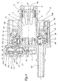
- the tip A comprises a sleeve 1 forming a seat 2 against which is pressed, by a force E 1 generated by a spring 3, a valve 4 housed in the inner volume 5 defined by the sleeve 1.
- the sleeve 1 is of substantially cylindrical and centered on the X-X 'axis.
- the sleeve 1 is mounted on a base 6 by any suitable means, e.g., by tight connection by cooperation of shapes with the rings 6 and 6b provided on the base 6, centered about the axis XX 'and intended to cooperate with corresponding wedging zones 1a and 1b provided on the sleeve 1.
- the base 6 is connected in sealed manner to a cap 7 by cooperation of shapes.
- the elements 1, 6 and 7 form the body of the tip A.
- the cap 7 is extended, opposite the sleeve 1, by a tube 8 with which it is integral and on which is connected the pipe C 1 . Between the base 6 and the cap 7 is defined a transition volume 9 connecting the internal volume of the tube 8 to the volume 5.
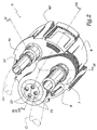
- cap 7 appears more particularly in Figure 2. It does not cover the entire base 6 on the back of the tip A. In its part 6 c not covered by the cap 7, the base 6 is extended by a tube 10 connected through the conduit C 2 to the top of the reservoir R. As is apparent from Figure 4, the interior volume of tube 10 is connected to an annular chamber 11 defined between the rings 6a and 6b, centered on the axis XX 'and surrounding the sleeve 1, that is to say the volume 5.
- An annular ring 12 extends radially outwardly from the sleeve 1 between the zones 1a and 1b, the annular ring forming the side of the chamber 11 two seats 13a and 13b in the form of annular beads against which rests on another valve 14 subjected to an elastic force E 2 generated by a compression spring 15.
- valves 4 and 14 have their respective front faces 4a and 14a made of elastomer and slightly concave. Thus, the valve 14 provides a tight seal at the seat 13.
- the ring 12 is pierced with six lights 16 in the shape of a circular arc distributed around the axis XX 'and allowing the flow of fluid, in particular vapors from the tube 10, when the valve 14 is spaced from the seats 13 a and 13 b .
- Volume 11 is also in communication, through an opening 17, with a regulation assembly 20 or pressure balance between the pressure inside of the chamber 11 and the atmospheric pressure.
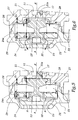
- the structure and the operation of the set 20 appear more clearly in Figures 5 and 6.
- the assembly 20 comprises a valve main 21 globally cylindrical, with a curve generator and centered on an axis A-A 'parallel to the axis X-X'.
- the valve 21 is disposed within a volume 22 defined between the base 6 and the cap 7. At the level of the volume 22, the cap 7 is pierced with four orifices 23 distributed around the axis A-A ', as shown in Figure 2.
- auxiliary valve 24 capable of translation movements, parallel to the axis A-A ', relative to the valve 21.
- the valve 24, which is annular and mounted around the valve 21, is intended to come against a seat 25 formed on a peripheral edge of the main valve 21.
- a spring 26 is disposed between the valve 24 and the base 6 by exerting on this valve 24 an elastic force E 3 directed towards the cap 7.
- a second spring 27 is disposed between the valve 24 and a flange 28 of the valve 21, opposite the seat 25 so that it exerts on the valve 24 a force E 4 tending to press the valve 24 against the seat 25.
- the effort E 3 tends, in turn, to press the assembly formed of the valve 21 and the valve 24 against a seat 29 formed by the cap 7.
- the springs 26 and 27 plate the two valves 21 and 24 respectively against the seats 29 and 25, so that there is no communication fluidic between the chamber 11 and the ambient atmosphere.
- the assembly 20 is permanently operational, independently the connection of the tip A with the tip B.
- the valve 14 carries three projections 34 in the form of an arc of circle whose geometry is such that they can cross some of the lights 16.
- the protrusions 34 are regularly distributed around the X-X 'axis just like the lights 16, of so, that the valve 34 can be mounted in different positions relative to the crown 12, the three protrusions 34 being in place in some of the six lights 16.
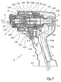
- the female connector B includes a multi body 101 defined by a first sleeve 102 on which is mounted a second sleeve 103 while an inner sleeve 104 is fixed in the sleeve 103 by cooperation of shapes with an internal shoulder 103 of justify- above and with the radially outer part 105 has a pusher 105 positioned on the central axis XX 'of the body 101.
- a valve 106 is disposed around the pusher 105 in the interior volume 107 of the sleeve 104 by being elastically loaded by a force E 5 generated by a spring 108 disposed between the valve 106 and the portion 105a of the pusher 105.
- O-rings 109 and 109 allow seal respectively between the valve 106 and the plunger 105 and between the valve 106 and the sleeve 104.
- the body 101 formed of the sleeves 102 to 104 is movable inside a base 110, generally in the form of a sleeve and kinematically connected to the carcass of the pistol P.
- the parts 101 and 110 are coaxial and centered on the X axis -X '. According to a not shown variant of the invention, they could be juxtaposed.
- a spring 112 is provided to exert on the body 101 a force E 6 tending to move it away from the outlet 113 of the pistol P.
- a trigger 115 is provided on the gun P and includes a surface 115 is inclined relative to the axis XX 'and arranged to cooperate with a corner 116 that can move in a direction YY' substantially perpendicular to the axis X X '.
- the wedge 116 prevents activating the trigger 115 when a ring 143 is not in the advanced position towards the end. The presence of this ring 143 in the rear position hinders the ascent to the corner 116 in the representation of FIG. 7, and therefore to the translation of the trigger 115.
- the trigger 115 When the trigger 115 is activated, it acts on an air distributor 116 'which sends air into a piloting sector 144, between joints J 1 and J 2 .
- the difference in section between these joints, on which the piloting pressure acts, makes it possible to advance the body 101, and in particular the pusher 105 and the valve 106, toward the outlet 113 of the pistol P while the body 101 remains energized.
- fuel additive through the pipe 118 which is deformed between the position shown in solid lines and that shown in phantom in Figure 7.
- Elastic tabs 40 are provided at a outer skirt 41 of the tip A and their free ends respective ones each form a spout 42 capable of being engaged in an external peripheral groove 142 of the base 110.
- the ring 143 of the pistol P retains the legs 40 in configuration engaged in the groove 142, which ensures a locking in coupled position of the tips A and B, independently of the position of the flaps.
- the plunger 105 Upon mating, the plunger 105 exerts on the front face 4a of the valve 4 a force tending to push it towards the inside of volume 5 against the force E 1 while the front face 1c of body 1 pushes the valve 106 against the force E 5 , which has the effect of allowing a flow E of additive pipe 118 to the tube 8, that is to say to allow the filling of the reservoir R via lines C ' 1 and C 1 .
- the front face 103 b of the sleeve 103 acts on the projections 34 a E 8 effort off the valve 14 seats 13a and 13b, which allows a flow E ' vapors contained in the chamber 11 through the lights 16, and very particularly, through the three lights 16 in which are not engaged the projections 34.
- the flow E 'from the chamber 11 is propagated in the gun P thanks to the free volume defined between the base 110 and the outer surface of the sleeve 1 which exists due to depressions 1 d formed at the periphery of the sleeve 1 between ribs 1 e .
- a collector 119 of the various components of the flow E 'from the depressions 1 d is defined between the body 1 and the base 110, the collector being connected to the depressions by one of a plurality of notches 104 formed at the edge 104 b
- the manifold 119 is also connected by several grooves 120 to an annular zone 121 connected by one or more radial orifices 122 to the housing 123 of the spring 112 which is itself connected to the pipe C 'by an orifice 124.
- the ends A and B thus make it possible to create a quick coupling allowing the circulation of a liquid of the pipe C ' 1 towards the pipe C 1 and the collection of the vents of the tank R, from the pipe C 2 to the pipe C' 2 , putting in communication these different lines being exerted by a simple pushing force of the pistol P to the tip A fixed on the vehicle.
- the communication between the various pipes C 1 and C ' 1 , C 2 and C' 2 being automatically performed, an operator is not likely to forget to collect the vents of the tank when it fills.
- a tube 150 may be connected to the cap 7 by a first end 150 a, while its second end 150 b enables communication formatting the assembly 20 with the ambient atmosphere above the maximum height H of liquid for which the vehicle is designed. It is therefore possible to provide to mount the tip A in the lower part of a motor vehicle, which allows to consider filling the tank from below the vehicle, without risk that a deposit, especially muddy, does not come into question the operation of the assembly 20.
- valve 14 can be divided into several individual flaps having, for example, revolution profiles and being associated with individual springs that charge them to corresponding seats.
- valve 14 has been represented with a valve 14 provided with protrusions 34 allowing its control through the lights 16.
- this valve could be ordered from any other without departing from the scope of the present invention.
- valves 4 and 14 may not be coaxial, the vents evacuation damper which may, for example, be controlled by a finger belonging to the pistol P.
- valve 14 could operate automatically, that is to say under the effect of the vapor pressure generated in the tank during its filling liquid, this valve thus fulfilling the functions of the valves 14 and 21 described above, without being controlled by an element of the complementary connector, such that the front face 103 b of the sleeve 3. a single flap is then used instead of the valves 14 and 21, said valve being movable in a single housing corresponding to dwellings 11 and 22.
- the opening of the valve 14 may occur under the effect of the depression caused in the suction chamber formed by the pipe C ' 2 , this depression being of the order of 100 mbar.
Landscapes
- Engineering & Computer Science (AREA)
- Mechanical Engineering (AREA)
- Quick-Acting Or Multi-Walled Pipe Joints (AREA)
- Cooling, Air Intake And Gas Exhaust, And Fuel Tank Arrangements In Propulsion Units (AREA)
Description
- au moins un premier clapet à ouverture commandée chargé par un premier effort en direction d'un siège et mobile à l'intérieur d'un premier logement formé par ce corps, ce premier clapet étant apte à obturer sélectivement un trajet d'écoulement de liquide en direction du réservoir,
- au moins un second clapet chargé par un second effort en direction d'un siège et mobile à l'intérieur d'un second logement formé par ce corps, ce second clapet étant apte à obturer ou à libérer un trajet d'écoulement de gaz en direction du réservoir, et
- au moins un troisième clapet ou clapet d'évacuation chargé par un troisième effort en direction d'un siège et mobile à l'intérieur d'un troisième logement formé par ce corps ou à l'intérieur du second logement, ce troisième clapet étant apte à obturer ou à libérer un trajet d'écoulement de gaz en provenance du réservoir.
- Il comprend deux clapets d'évacuation dont l'un est à ouverture commandée et dont l'autre est à ouverture automatique par différence de pression.
- Le troisième logement est à section annulaire centrée sur un axe principal du premier logement, ce troisième logement étant disposé radialement à l'extérieur du premier logement. Dans ce cas, on peut prévoir que le troisième clapet est en forme d'anneau ou de secteur d'anneau.
- Le troisième clapet est pourvu d'un organe de commande apte à coopérer avec un élément cinématiquement lié à un embout d'accouplement complémentaire appartenant au raccord rapide, pour le déplacement du troisième clapet à l'encontre du troisième effort précité. Dans ce cas, le troisième clapet porte avantageusement au moins une partie en saillie s'étendant, à travers une ouverture d'une cloison du troisième logement, en direction de l'embout d'accouplement complémentaire lorsque les embouts sont raccordés ou proches d'être raccordés. Cette partie en saillie permet une manoeuvre du troisième clapet pendant le mouvement de rapprochement des embouts qui a lieu lors de la fermeture du raccord.
- La partie du premier clapet et/ou du troisième clapet apte à venir en appui contre un siège est réalisée en élastomère et présente une face avant légèrement concave. Le matériau et la géométrie employée pour ce ou ces clapets assure une excellente étanchéité en position fermée et une coupure nette, sans égoutture.
- Un ensemble de régulation de pression est prévu dans l'embout récepteur, cet ensemble étant relié à l'atmosphère ambiante et incorporant au moins le second clapet. Cet ensemble comprend avantageusement un clapet principal formé par le troisième clapet et chargé élastiquement en direction d'un siège formé dans un corps de l'embout récepteur, et un clapet secondaire formé par le second clapet et chargé élastiquement en direction d'un siège formé sur le clapet principal.
- Le premier trajet ménagé dans l'embout est un trajet d'écoulement de fluide de remplissage du réservoir alors que le second trajet ménagé dans l'embout est un trajet d'écoulement des évents en provenance de ce réservoir lors de son remplissage.
- L'un des embouts du raccord est monté à demeure sur le véhicule, l'autre embout appartenant à une station de remplissage du réservoir. Dans ce cas, on peut prévoir que l'embout récepteur monté à demeure sur le véhicule est équipé d'un ensemble comprenant au moins un clapet de régulation de pression, cet ensemble étant disposé à une première extrémité d'une tubulure dont la seconde extrémité est positionnée au-dessus du niveau maximum de liquide dans lequel est prévu pour rouler ce véhicule. Cette disposition permet de garantir que l'ensemble de régulation de pression est en permanence en relation avec l'atmosphère ambiante sans risque d'encrassement dû à des dépôts de boue ou autres salissures.
- la figure 1 est une vue en perspective éclatée par l'avant, avec arrachements partiels d'un premier embout de raccord rapide récepteur conforme à l'invention, les ressorts de cet embout n'étant pas représentés ;
- la figure 2 est une vue en perspective par l'arrière de l'embout de la figure 1 ;
- la figure 3 est une coupe selon la ligne III-III à la figure 2 ;
- la figure 4 est une coupe selon la ligne IV-IV à la figure 2 ;
- la figure 5 est une vue de détail à plus grande échelle du détail V à la figure 4 dans une première configuration de fonctionnement ;
- la figure 6 est une vue du détail de la figure 5 dans une seconde configuration de fonctionnement ;
- la figure 7 est une coupe transversale d'un raccord conforme à l'invention en cours d'accouplement, ce raccord comprenant un embout d'accouplement représenté aux figures 1 à 6 et un embout d'accouplement complémentaire inclus dans un outil à main, le plan de coupe étant indiqué par la ligne VII-VII à la figure 2 et
- la figure 8 est une coupe analogue à la figure 7 alors que les embouts sont accouplés, l'outil à main n'étant pas représenté.
Claims (15)
- Embout récepteur de raccord rapide pour le remplissage d'un réservoir embarqué sur un véhicule automobile, ledit réservoir étant susceptible de contenir un liquide et un gaz, ledit embout comprenant, dans un corps (1, 6, 7) embarqué sur ledit véhicule,au moins un premier clapet (4) à ouverture commandée, chargé par un premier effort (E1) en direction d'un siège (2) et mobile à l'intérieur d'un premier logement (5) formé par ledit corps (1), ledit premier clapet étant apte à obturer sélectivement un trajet d'écoulement (E) de liquide en direction dudit réservoir (R) etau moins un second clapet (24) chargé par un second effort (E3) en direction d'un siège (29) et mobile à l'intérieur d'un second logement (22) formé par ledit corps (6, 7), ledit second clapet étant apte à obturer ou à libérer un trajet d'écoulement (A) de gaz en direction dudit réservoir caractérisé en ce que ledit embout comprend au moins un troisième clapet (14, 21) ou clapet d'évacuation, chargé par un troisième effort (E2, E4) en direction d'un siège (13a, 13b, 25) et mobile à l'intérieur d'un troisième logement (11) formé par ledit corps (6, 7) ou à l'intérieur dudit second logement (22), ledit troisième clapet étant apte à obturer ou à libérer un trajet d'écoulement (E', V) de gaz en provenance dudit réservoir.
- Embout récepteur selon la revendication 1, caractérisé en ce qu'il comprend deux clapets (14, 21) d'évacuation dont l'un (14) est à ouverture commandée et dont l'autre (21) est à ouverture automatique par différence de pression.
- Embout récepteur selon l'une des revendications 1 ou 2, caractérisé en ce que ledit troisième logement (11) est à section annulaire centrée sur un axe principal (X-X') dudit premier logement (5), ledit troisième logement étant disposé radialement à l'extérieur dudit premier logement.
- Embout récepteur selon la revendication 3, caractérisé en ce que ledit troisième clapet (14) est en forme d'anneau ou de secteur d'anneau.
- Embout récepteur selon l'une des revendications précédentes, caractérisé en ce que ledit troisième clapet (14) est pourvu d'un organe de commande (34) apte à coopérer avec un élément (103b) cinématiquement lié à un embout complémentaire (B) du raccord pour le déplacement dudit troisième clapet à l'encontre dudit troisième effort (E2).
- Embout récepteur selon l'une des revendications précédentes, caractérisé en ce que ledit troisième clapet porte au moins une partie en saillie (34) s'étendant, à travers une ouverture (16) d'une cloison (12) dudit troisième logement (11), en direction dudit embout complémentaire (B) lorsque lesdits embouts sont raccordés ou proches d'être raccordés.
- Embout récepteur selon l'une des revendications précédentes, caractérisé en ce que la partie (4a, 14a) dudit premier clapet (4) et/ou dudit troisième clapet (14) apte à venir en appui contre un siège (2, 13a, 13b) est réalisée en élastomère et présente une face avant légèrement concave.
- Embout récepteur selon l'une des revendications précédentes, caractérisé en ce qu'il comprend un ensemble (20) de régulation de pression relié, à l'atmosphère ambiante et incorporant au moins ledit second clapet (24).
- Embout récepteur selon la revendication 8, caractérisé en ce que ledit ensemble (20) comprend un clapet principal (21), formé par ledit troisième clapet et chargé élastiquement (E3) en direction d'un siège (29) formé dans un corps (1, 6, 7) dudit embout, et un clapet secondaire (24), formé par ledit second clapet et chargé élastiquement en direction d'un siège (25) formé sur ledit clapet principal.
- Embout d'accouplement de raccord rapide, ledit embout (B) comprenant un clapet (106), mobile à l'intérieur d'un logement (107) formé par un corps (101, 110) dudit embout, entre une première position où il obture et une seconde position où il libère un premier trajet (E) d'écoulement de fluide de ou vers une première canalisation (C'1), ledit clapet étant apte à être commandé par un organe (1c) d'un embout récepteur complémentaire (A) selon l'une des revendications précédentes et qui appartient audit raccord, le corps dudit embout comprenant deux parties (101, 110) mobiles l'une par rapport à l'autre, un second trajet (119-121) d'écoulement (E') de fluide de ou vers une seconde canalisation (C'2) étant au moins partiellement défini entre lesdites deux parties, l'une desdites parties (101) formant organe d'actionnement d'un clapet (14) de l'embout récepteur complémentaire (A), caractérisé en ce que ledit embout d'accouplement (B) est intégré dans un outil à main (P) pourvu d'une gâchette (115) de commande de la position relative desdites deux parties (101, 110) dudit corps.
- Raccord rapide de sécurité pour la jonction amovible de deux fois deux canalisations (C1, C2, C'1, C'2), caractérisé en ce qu'il comprend au moins un embout récepteur et/ou d'accouplement (A, B) selon l'une des revendications précédentes.
- Système de remplissage d'un réservoir (R) embarqué ou à embarquer sur un véhicule automobile comprenant au moins un raccord rapide selon la revendication 11.
- Système selon la revendication 12, caractérisé en ce que ledit premier trajet ménagé dans ledit embout récepteur et/ou d'accouplement (A, B) est un trajet d'écoulement (E) du fluide de remplissage dudit réservoir (R) alors que ledit second trajet ménagé dans ledit embout est un trajet d'écoulement (E') des évents en provenance dudit réservoir lors de son remplissage.
- Système selon l'une des revendications 12 ou 13, caractérisé en ce que l'un des embouts (A) du raccord est monté à demeure sur ledit véhicule, l'autre embout(B) appartenant à une station de remplissage du réservoir (R).
- Système selon la revendication 14, caractérisé en ce que ledit embout (A) monté à demeure sur ledit véhicule est équipé d'un ensemble (20) de régulation de pression, ledit ensemble étant disposé à une première extrémité (150a) d'une tubulure (150) dont la seconde extrémité (150b) est positionnée au dessus du niveau maximum (H) de liquide dans lequel est prévu pour rouler ledit véhicule.
Applications Claiming Priority (2)
| Application Number | Priority Date | Filing Date | Title |
|---|---|---|---|
| FR0003472 | 2000-03-17 | ||
| FR0003472A FR2806353B1 (fr) | 2000-03-17 | 2000-03-17 | Embout de raccord rapide, raccord rapide comprenant un tel embout et systeme de remplissage d'un reservoir embarque comprenant un tel raccord |
Publications (2)
| Publication Number | Publication Date |
|---|---|
| EP1136437A1 EP1136437A1 (fr) | 2001-09-26 |
| EP1136437B1 true EP1136437B1 (fr) | 2005-06-08 |
Family
ID=8848232
Family Applications (1)
| Application Number | Title | Priority Date | Filing Date |
|---|---|---|---|
| EP20010420064 Expired - Lifetime EP1136437B1 (fr) | 2000-03-17 | 2001-03-13 | Embout de raccord rapide, raccord rapide comprenant un tel embout et système de remplissage d'un réservoir embarqué comprenant un tel raccord |
Country Status (4)
| Country | Link |
|---|---|
| EP (1) | EP1136437B1 (fr) |
| DE (1) | DE60111294T2 (fr) |
| ES (1) | ES2240378T3 (fr) |
| FR (1) | FR2806353B1 (fr) |
Family Cites Families (2)
| Publication number | Priority date | Publication date | Assignee | Title |
|---|---|---|---|---|
| US3171448A (en) * | 1961-03-15 | 1965-03-02 | Protectoseal Co | Fluid connection |
| DE4036901A1 (de) * | 1990-11-20 | 1992-05-21 | Walther Carl Kurt Gmbh | Schnellverschluss-kupplung |
-
2000
- 2000-03-17 FR FR0003472A patent/FR2806353B1/fr not_active Expired - Fee Related
-
2001
- 2001-03-13 EP EP20010420064 patent/EP1136437B1/fr not_active Expired - Lifetime
- 2001-03-13 ES ES01420064T patent/ES2240378T3/es not_active Expired - Lifetime
- 2001-03-13 DE DE2001611294 patent/DE60111294T2/de not_active Expired - Lifetime
Also Published As
| Publication number | Publication date |
|---|---|
| FR2806353A1 (fr) | 2001-09-21 |
| ES2240378T3 (es) | 2005-10-16 |
| DE60111294T2 (de) | 2006-03-16 |
| FR2806353B1 (fr) | 2002-07-12 |
| DE60111294D1 (de) | 2005-07-14 |
| EP1136437A1 (fr) | 2001-09-26 |
Similar Documents
| Publication | Publication Date | Title |
|---|---|---|
| EP1551560B1 (fr) | Distributeur de produit fluide | |
| EP1333218B1 (fr) | Raccord rapide pour la jonction amovible de deux canalisations | |
| EP0511894B1 (fr) | Dispositif pour la distribution de mousse | |
| EP0129465B1 (fr) | Dispositif de pulvérisation pour récipient déformable | |
| EP0486355A1 (fr) | Distributeur de produit, liquide à pâteux, et embase pour un tel distributeur | |
| EP3567348A1 (fr) | Reservoir pour fluide ameliore | |
| FR2862369A1 (fr) | Element femelle de raccord et raccord rapide incorporant un tel element | |
| WO2014096722A1 (fr) | Distributeur de produit fluide rechargeable | |
| FR2819221A1 (fr) | Dispositif de mise a l'air libre destine a un reservoir de vehicule automobile | |
| FR3039114A1 (fr) | Dispositif de nettoyage d'un capteur pour vehicule automobile | |
| WO1989000683A1 (fr) | Procede et dispositif de repartition d'un volume primaire de fluide en un nombre determine de volumes secondaires presentant une relation predefinie entre eux | |
| FR2690483A1 (fr) | Pompe à pistons radiaux, notamment pompe de carburant pour moteur à combustion interne. | |
| WO2003066234A1 (fr) | Dispositif d' échantillons de parfum | |
| EP3195983B1 (fr) | Outil de fixation a gaz et son procede de fonctionnement | |
| EP1136437A1 (fr) | Embout de raccord rapide, raccord rapide comprenant un tel embout et système de remplissage d'un réservoir embarqué comprenant un tel raccord | |
| EP0653603B1 (fr) | Dispositif d'éjection simultanée de deux fluides, notamment pyrotechniques | |
| EP0459866A1 (fr) | Dispositif de circuit de ventilation d'air d'un réservoir de carburant | |
| EP3181297B1 (fr) | Cartouche de combustible pour un outil de fixation a gaz et outil de fixation a gaz comportant une telle cartouche | |
| WO2008132413A2 (fr) | Distributeur de produit fluide | |
| FR3088404A1 (fr) | Dispositif de raccordement à fourrure mobile | |
| WO2019025696A1 (fr) | Dispositif de régulation de pression et son procédé d'assemblage, pour un absorbeur de vapeurs de carburant | |
| EP0548350B1 (fr) | Recipient pulverisateur | |
| EP0778190B1 (fr) | Cylindre pour un dispositif de commande hydraulique d'un embrayage de véhicule automobile | |
| WO2014184483A1 (fr) | Distributeur de produit fluide | |
| EP0069816A1 (fr) | Ensemble de tirage d'un liquide au moyen d'un gaz sous pression |
Legal Events
| Date | Code | Title | Description |
|---|---|---|---|
| PUAI | Public reference made under article 153(3) epc to a published international application that has entered the european phase |
Free format text: ORIGINAL CODE: 0009012 |
|
| AK | Designated contracting states |
Kind code of ref document: A1 Designated state(s): AT BE CH CY DE DK ES FI FR GB GR IE IT LI LU MC NL PT SE TR Kind code of ref document: A1 Designated state(s): DE ES FR |
|
| AX | Request for extension of the european patent |
Free format text: AL;LT;LV;MK;RO;SI |
|
| 17P | Request for examination filed |
Effective date: 20011109 |
|
| AKX | Designation fees paid |
Free format text: DE ES FR |
|
| 17Q | First examination report despatched |
Effective date: 20040723 |
|
| GRAP | Despatch of communication of intention to grant a patent |
Free format text: ORIGINAL CODE: EPIDOSNIGR1 |
|
| GRAS | Grant fee paid |
Free format text: ORIGINAL CODE: EPIDOSNIGR3 |
|
| GRAA | (expected) grant |
Free format text: ORIGINAL CODE: 0009210 |
|
| AK | Designated contracting states |
Kind code of ref document: B1 Designated state(s): DE ES FR |
|
| REF | Corresponds to: |
Ref document number: 60111294 Country of ref document: DE Date of ref document: 20050714 Kind code of ref document: P |
|
| REG | Reference to a national code |
Ref country code: ES Ref legal event code: FG2A Ref document number: 2240378 Country of ref document: ES Kind code of ref document: T3 |
|
| PLBE | No opposition filed within time limit |
Free format text: ORIGINAL CODE: 0009261 |
|
| STAA | Information on the status of an ep patent application or granted ep patent |
Free format text: STATUS: NO OPPOSITION FILED WITHIN TIME LIMIT |
|
| 26N | No opposition filed |
Effective date: 20060309 |
|
| REG | Reference to a national code |
Ref country code: FR Ref legal event code: PLFP Year of fee payment: 16 |
|
| REG | Reference to a national code |
Ref country code: FR Ref legal event code: PLFP Year of fee payment: 17 |
|
| REG | Reference to a national code |
Ref country code: FR Ref legal event code: PLFP Year of fee payment: 18 |
|
| PGFP | Annual fee paid to national office [announced via postgrant information from national office to epo] |
Ref country code: FR Payment date: 20190325 Year of fee payment: 19 Ref country code: DE Payment date: 20190327 Year of fee payment: 19 |
|
| PGFP | Annual fee paid to national office [announced via postgrant information from national office to epo] |
Ref country code: ES Payment date: 20190401 Year of fee payment: 19 |
|
| REG | Reference to a national code |
Ref country code: DE Ref legal event code: R119 Ref document number: 60111294 Country of ref document: DE |
|
| PG25 | Lapsed in a contracting state [announced via postgrant information from national office to epo] |
Ref country code: DE Free format text: LAPSE BECAUSE OF NON-PAYMENT OF DUE FEES Effective date: 20201001 Ref country code: FR Free format text: LAPSE BECAUSE OF NON-PAYMENT OF DUE FEES Effective date: 20200331 |
|
| REG | Reference to a national code |
Ref country code: ES Ref legal event code: FD2A Effective date: 20210729 |
|
| PG25 | Lapsed in a contracting state [announced via postgrant information from national office to epo] |
Ref country code: ES Free format text: LAPSE BECAUSE OF NON-PAYMENT OF DUE FEES Effective date: 20200314 |