EP1136611A2 - Breithalter für schlauchförmige Maschenware - Google Patents
Breithalter für schlauchförmige Maschenware Download PDFInfo
- Publication number
- EP1136611A2 EP1136611A2 EP01830185A EP01830185A EP1136611A2 EP 1136611 A2 EP1136611 A2 EP 1136611A2 EP 01830185 A EP01830185 A EP 01830185A EP 01830185 A EP01830185 A EP 01830185A EP 1136611 A2 EP1136611 A2 EP 1136611A2
- Authority
- EP
- European Patent Office
- Prior art keywords
- stretcher
- fabric
- pulleys
- arms
- advancement
- Prior art date
- Legal status (The legal status is an assumption and is not a legal conclusion. Google has not performed a legal analysis and makes no representation as to the accuracy of the status listed.)
- Withdrawn
Links
Images


Classifications
-
- D—TEXTILES; PAPER
- D06—TREATMENT OF TEXTILES OR THE LIKE; LAUNDERING; FLEXIBLE MATERIALS NOT OTHERWISE PROVIDED FOR
- D06B—TREATING TEXTILE MATERIALS USING LIQUIDS, GASES OR VAPOURS
- D06B23/00—Component parts, details, or accessories of apparatus or machines, specially adapted for the treating of textile materials, not restricted to a particular kind of apparatus, provided for in groups D06B1/00 - D06B21/00
- D06B23/08—Untwisting devices
-
- D—TEXTILES; PAPER
- D06—TREATMENT OF TEXTILES OR THE LIKE; LAUNDERING; FLEXIBLE MATERIALS NOT OTHERWISE PROVIDED FOR
- D06C—FINISHING, DRESSING, TENTERING OR STRETCHING TEXTILE FABRICS
- D06C5/00—Shaping or stretching of tubular fabrics upon cores or internal frames
Definitions
- the object of the present invention is a stretcher for tubular knitwear fabric, to be applied in particular to calenders and other machines for the treatment of tubular fabric.
- tubular fabric stretchers hav-ing arms provided with fabric advancement wheels, such as described in patent PCT/IT99/00344 issued to the same proprietor of the present invention.
- the present invention offers the possibility of causing the fabric to take an advantageous helical ad-vancement motion.
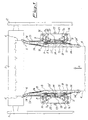
- the subject stretcher is comprised of stanchions 1 and 2 in which the various control and drive mechanisms are contained.
- Said stanchions support the per se known steamer 3, inside which the tubular fabric is caused to run after passing through the stretcher.
- Said stretcher is comprised of the stretcher arms 5 and 6, which in turn are held on the hereinbelow described support devices.
- motor means herein-below described transmit the motion to the upper drive wheels 7a, and thus means not shown in the figure can de-termine the displacement in opposite directions of the stretcher arms 5 and 6, so as to possibly change the width of the tubular fabric.
- the upper drive wheels 7a are coupled to the similar lower wheels 7b through means that are specified hereinbelow.
- the stretcher arms 5 and 6 are provided with wheels or rings 8 that are suitably shaped and are arranged in front of the convex part the drive wheels 7a and 7b are provided with.
- the latter in turn exhibit the supports 9 that carry the inclined axis (12) wheel pairs 10 and 11.
- Said wheels 10 and 11 are spaced apart with their periph-eral parts from the circumferential outlines 8' of rings 8, this being due to the magnetic attraction force, as will be described the later on.
- the transportation of the tubular for fabric 4 is obtained by means of belts 13 that are wound around the set of idle pulleys 14 on arms 5 and 6 along the out-lines of the drive wheels 7a and7b and of the rings 8.
- both of the inclined wheels 10 our motor driven as they are cou-pled to one another by means of an elastic belt 15 that is wound on drive wheels 7a and7b.
- Said motor drive has the advantage that the transportation of the fabric is markedly improved.
- the supports 9 consist of fork shaped ????? 16 for the adjustment of the working angles of arms 5 and 6.
- the wheels 10 and 11 are kept spaced apart from the rings 8 by means of magnets 17 and 18 that respec-tively attract arms 5 and 6 outwards as shown by arrows B.
- said rings 8 carried by arms 5 and 6 remain spaced apart from the inclined wheels 10 and 11, and are at-tracted against the drive wheels 7a and 7b by said mag-nets 17 and 18, and the fabric is advanced between belts 13 and the drive wheels 7a and 7b.
- Said adjustment is obtained by means of a mechanism that takes the magnets 17 and 18 closer to a farther from arms 5 and 6 respectively.
- magnets 17 and 18 are coupled to said mechanism that is provided with an adjustment hand grip 19 that is adapted to move closer or farther the magnets 17 and 18 to and from sup-ports 17' and 18' that are fixed to bars 5 and 6.
- guards 20 are provided above the mechanisms carrying the adjustment handgrips 19.
- the apparatus is operated as follows: the tu-bular fabric 4, that usually consists of various tubular pieces that are sewn together, is introduced upwards, as can be seen from figures 1 and 2, between wheels 10 and 11 and ring 8 and between ring 8 and wheels 7a and 7b of each arm and is thus transported upwards as indicated by arrow A upon rotation of the drive wheels 7a and 7b that are coupled to rings 8 and to pulleys 14 that are mounted on the arms 5 and 6, said arms being kept in position and sustained by the attraction force of magnets 17 and 18.
- the arms 5 and 6 are displayed relative to one another until they reach the maximum dis-tance shown in the positions of figure 1.
- the novelty of the present invention concerns the inclination in either direction of the lower pulleys 14' for the advancement of fabric 4 with the consequent ad-vancement of fabric 4 with a right (d) or left (s) heli-cal component, as it is clearly shown in figures 3a and 3b, respectively.
- pulley 14' is comprised between the branches 5' and 6' that form arms 5 and 6, respectively.
- pulley 14' is inclined at an angle relative to line X in the direction of arrow A.
- pulley 14' is inclined at an angle relative to line X in the direction of arrow B.
Landscapes
- Engineering & Computer Science (AREA)
- Textile Engineering (AREA)
- Treatment Of Fiber Materials (AREA)
Applications Claiming Priority (2)
| Application Number | Priority Date | Filing Date | Title |
|---|---|---|---|
| IT2000MI000600A IT1316827B1 (it) | 2000-03-22 | 2000-03-22 | Allargatore di tessuti tubolari con pulegge inferiori di avanzamentodel tessuto inclinabili |
| ITMI000600 | 2000-03-22 |
Publications (2)
| Publication Number | Publication Date |
|---|---|
| EP1136611A2 true EP1136611A2 (de) | 2001-09-26 |
| EP1136611A3 EP1136611A3 (de) | 2003-04-09 |
Family
ID=11444583
Family Applications (1)
| Application Number | Title | Priority Date | Filing Date |
|---|---|---|---|
| EP01830185A Withdrawn EP1136611A3 (de) | 2000-03-22 | 2001-03-16 | Breithalter für schlauchförmige Maschenware |
Country Status (2)
| Country | Link |
|---|---|
| EP (1) | EP1136611A3 (de) |
| IT (1) | IT1316827B1 (de) |
Cited By (2)
| Publication number | Priority date | Publication date | Assignee | Title |
|---|---|---|---|---|
| ITTO20110069A1 (it) * | 2011-01-26 | 2012-07-27 | Bianco Spa | Gruppo di torsione per ruotare un tessuto tubolare |
| WO2015008098A1 (en) * | 2013-07-18 | 2015-01-22 | Lagogiannis Georgios | Knitting spirality stabilizer |
Family Cites Families (2)
| Publication number | Priority date | Publication date | Assignee | Title |
|---|---|---|---|---|
| FR2609734B1 (fr) * | 1987-01-16 | 1989-05-05 | Domisse | Dispositif d'introduction dans une machine et de detorsion des tissus tricotes en tubulaire et machine equipee d'un tel dispositif |
| IT1271712B (it) * | 1994-11-09 | 1997-06-04 | Ferraro Srl Flli | Allargatore migliorato in calandre per tessuti di maglia tubolari |
-
2000
- 2000-03-22 IT IT2000MI000600A patent/IT1316827B1/it active
-
2001
- 2001-03-16 EP EP01830185A patent/EP1136611A3/de not_active Withdrawn
Cited By (3)
| Publication number | Priority date | Publication date | Assignee | Title |
|---|---|---|---|---|
| ITTO20110069A1 (it) * | 2011-01-26 | 2012-07-27 | Bianco Spa | Gruppo di torsione per ruotare un tessuto tubolare |
| WO2015008098A1 (en) * | 2013-07-18 | 2015-01-22 | Lagogiannis Georgios | Knitting spirality stabilizer |
| US9476153B2 (en) | 2013-07-18 | 2016-10-25 | Georgios LAGOGIANNIS | Knitting spirality stabilizer |
Also Published As
| Publication number | Publication date |
|---|---|
| IT1316827B1 (it) | 2003-05-12 |
| ITMI20000600A0 (it) | 2000-03-22 |
| ITMI20000600A1 (it) | 2001-09-22 |
| EP1136611A3 (de) | 2003-04-09 |
Similar Documents
| Publication | Publication Date | Title |
|---|---|---|
| US8915101B2 (en) | Warp knitted fabric manufacturing method | |
| JP2682883B2 (ja) | 縫い付け中に織物の縁の側面を整列させる装置 | |
| JPH02213399A (ja) | アイロン装置 | |
| RU2009101001A (ru) | Устройство для обработки непрерывно подаваемых друг за другом плоских предметов или квазибесконечного полотна материала | |
| US3899986A (en) | Apparatus for guiding limp material | |
| US5867879A (en) | Stretcher in calenders for tubular knitted fabrics | |
| US6095070A (en) | Driving device for feeding material to be sewn in a sewing machine | |
| EP1258555A1 (de) | Vorrichtung zum breithalten von Warenbahnen | |
| EP1138817A2 (de) | Breithalter für schlauchförmige Maschenware | |
| KR200252514Y1 (ko) | 원단 공급장치 | |
| ATE84331T1 (de) | Breithalter fuer schlauchware mit differentialem antrieb der lieferrollen. | |
| EP1136612A2 (de) | Breithalter für schlauchförmige Maschenware | |
| EP1127184B1 (de) | Breithalter für schlauchförmige strickware mit magnetischer anziehungskraft | |
| GB2036116A (en) | Napping | |
| US3895623A (en) | Physical therapy machine | |
| ITMI20000600A1 (it) | Allargatore di tessuti tubolari con pulegge inferiori di avanzamento del tessuto inclinabili | |
| EP0197430B1 (de) | Blindstichnähmaschine | |
| US1232653A (en) | Dye-beck. | |
| JP2005314850A (ja) | シームレスベルトの作製方法及び装置 | |
| JPH07124356A (ja) | ミシンの補助送り装置 | |
| JP2533427B2 (ja) | 衣服縫目プレス機 | |
| US4309880A (en) | Patterning device for a warp knitting machine | |
| KR920003253B1 (ko) | 원단추진 장치를 갖는 재봉기 | |
| SU1618763A1 (ru) | Устройство дл глажени волос ного покрова меховых шкур | |
| JPS6241748B2 (de) |
Legal Events
| Date | Code | Title | Description |
|---|---|---|---|
| PUAI | Public reference made under article 153(3) epc to a published international application that has entered the european phase |
Free format text: ORIGINAL CODE: 0009012 |
|
| AK | Designated contracting states |
Kind code of ref document: A2 Designated state(s): AT BE CH CY DE DK ES FI FR GB GR IE IT LI LU MC NL PT SE TR |
|
| AX | Request for extension of the european patent |
Free format text: AL;LT;LV;MK;RO;SI |
|
| PUAL | Search report despatched |
Free format text: ORIGINAL CODE: 0009013 |
|
| AK | Designated contracting states |
Kind code of ref document: A3 Designated state(s): AT BE CH CY DE DK ES FI FR GB GR IE IT LI LU MC NL PT SE TR Designated state(s): AT BE CH CY DE DK ES FI FR GB GR IE IT LI LU MC NL PT SE TR |
|
| AX | Request for extension of the european patent |
Extension state: AL LT LV MK RO SI |
|
| AKX | Designation fees paid | ||
| REG | Reference to a national code |
Ref country code: DE Ref legal event code: 8566 |
|
| STAA | Information on the status of an ep patent application or granted ep patent |
Free format text: STATUS: THE APPLICATION IS DEEMED TO BE WITHDRAWN |
|
| 18D | Application deemed to be withdrawn |
Effective date: 20031010 |