EP1136612A2 - Elargisseur pour tricot tubulaire - Google Patents
Elargisseur pour tricot tubulaire Download PDFInfo
- Publication number
- EP1136612A2 EP1136612A2 EP01830186A EP01830186A EP1136612A2 EP 1136612 A2 EP1136612 A2 EP 1136612A2 EP 01830186 A EP01830186 A EP 01830186A EP 01830186 A EP01830186 A EP 01830186A EP 1136612 A2 EP1136612 A2 EP 1136612A2
- Authority
- EP
- European Patent Office
- Prior art keywords
- stretcher
- fabric
- coupled
- arms
- wheels
- Prior art date
- Legal status (The legal status is an assumption and is not a legal conclusion. Google has not performed a legal analysis and makes no representation as to the accuracy of the status listed.)
- Withdrawn
Links
Images


Classifications
-
- D—TEXTILES; PAPER
- D06—TREATMENT OF TEXTILES OR THE LIKE; LAUNDERING; FLEXIBLE MATERIALS NOT OTHERWISE PROVIDED FOR
- D06C—FINISHING, DRESSING, TENTERING OR STRETCHING TEXTILE FABRICS
- D06C5/00—Shaping or stretching of tubular fabrics upon cores or internal frames
Definitions
- the object of the present invention is a stretcher for tubular knitwear fabric, to be applied in particular to calenders and other machines for the treatment of tubular fabric.
- stretchers for tubular fabric with two stretcher arms along which the fabric slides by means of advancement wheels that are coupled by transmission belts.
- the object of the present invention is an improved electrical apparatus which is apt to cause the fabric to be advanced in a regular fashion, thereby obtaining the so-called "straight alignment" of the fabric edges with a highly accurate adjustment of the advancement speed for the two edges of the fabric.
- the apparatus comprises two independent electric motors with fine speed control that are respectively coupled with the advancement wheels for the two fabric edges.
- the subject stretcher is comprised of stanchions 1 and 2 in which the various control and drive mechanisms are contained.
- Said stanchions support the per se known steamer 3, through which the tubular fabric is caused to run after passing through the stretcher.
- Said stretcher is comprised of the stretcher arms 5 and 6, which in turn are held on the hereinbelow described support devices.
- motor means hereinbelow described transmit the motion to the upper drive wheels 7a, and thus means not shown in the figure can determine the displacement in opposite directions of the stretcher arms 5 and 6, so as to possibly change the width of the tubular fabric.
- the upper drive wheels 7a are coupled to the similar lower wheels 7b through means that are specified hereinbelow.
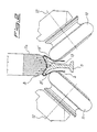
- the stretcher arms 5 and 6 are provided with wheels or rings 8 that are suitably shaped and are arranged in front of the convex part the drive wheels 7a and 7b are provided with.
- the latter in turn exhibit the supports 9 that carry the inclined axis (12) wheel pairs 10 and 11.
- Said wheels 10 and 11 are spaced apart with their peripheral parts from the circumferential outlines 8' of rings 8, this being due to the magnetic attraction force, as will be described later on.
- the transportation of the tubular fabric 4 is obtained by means of belts 13 that are wound around a set of idle pulleys 14 on arms 5 and 6 along the outlines of the drive wheels 7a and7b and of the rings 8.
- both of the inclined wheels 10 are motor-driven as they are coupled to one another by means of an elastic belt 15 that is wound on drive wheels 7a and7b.
- the inclined wheels 11 are motor driven as they are coupled by means of an elastic belt with the same drive wheels 7a and 7b.
- Said motor drive has the advantage that the transportation of the fabric is markedly improved.
- the supports 9 consist of fork shaped brackets 16 for the adjustment of the working angles of arms 5 and 6.
- wheels 10 and 11 are kept spaced apart from the rings 8 by means of magnets 17 and 18 that respectively attract arms 5 and 6 outwards as shown by arrows B.
- said rings 8 carried by arms 5 and 6 remain spaced apart from the inclined wheels 10 and 11, and are attracted against the drive wheels 7a and 7b by said magnets 17 and 18, and the fabric is advanced between belts 13 and the drive wheels 7a and 7b.
- Said adjustment is obtained by means of a mechanism that takes the magnets 17 and 18 closer to a farther from arms 5 and 6 respectively.
- magnets 17 and 18 are coupled to said mechanism that is provided with an adjustment hand grip 19, which is adapted to move closer or farther the magnets 17 and 18 to and from the supports 17' and 18' that are fixed to bars 5 and 6.
- guards 20 are provided above the mechanisms carrying the adjustment hand grips 19.
- the apparatus is operated as follows: the tubular fabric 4, that usually consists of various tubular pieces that are sewn together, is introduced upwards, as can be seen from figures 1 and 2, between wheels 10 and 11 and ring 8 and between ring 8 and wheels 7a and 7b of each arm and is thus transported upwards as indicated by arrow A upon rotation of the drive wheels 7a and 7b that are coupled to rings 8 and to pulleys 14 that are mounted on the arms 5 and 6, said arms being kept in position and sustained by the attraction force of magnets 17 and 18.
- the arms 5 and 6 are displayed relative to one another until they reach the maximum distance shown in the positions of figure 1.
- the stretcher can take all the positions from a minimum to a maximum distance without having to take care to substitute to stretcher, thus avoiding to stop the machine with the consequent slip off of the tubular from the stretcher arms.
- each are 5 and 6 carries an electric motor 21, each electric motor being coupled to the drive wheel 7a by means of a motor reducer 22 on the shaft 23 of which a pulley 24 is keyed, said pulley being coupled by means of a transmission belt 25 to a pulley 26 that is keyed onto the shaft 27 of a second drive. . wheel 7b.
- Electric means for the control of the speed of both motors 21 are provided, said means comprising two frequency converters that are connected to the respective motors 21, one for arm 5 and the other for arm 6.
- the speed of motors 21 can be synchronized or made different by means of the converter that is connected to a frequency change signal.
- the speed of motors 21 is the same and such a choice is adopted when the advancement of fabric 4 is a regular.
- the second case the speeds are different and can be controlled, and such a choice is adopted when one edge of fabric 4 advances faster than the other one.
Landscapes
- Engineering & Computer Science (AREA)
- Textile Engineering (AREA)
- Treatment Of Fiber Materials (AREA)
- Automatic Cycles, And Cycles In General (AREA)
- Transmissions By Endless Flexible Members (AREA)
Applications Claiming Priority (2)
| Application Number | Priority Date | Filing Date | Title |
|---|---|---|---|
| IT2000MI000601A IT1316828B1 (it) | 2000-03-22 | 2000-03-22 | Allargatore di tessuti tubolari con ruote di comando collegate amotori indipendenti |
| ITMI200601 | 2000-03-22 |
Publications (2)
| Publication Number | Publication Date |
|---|---|
| EP1136612A2 true EP1136612A2 (fr) | 2001-09-26 |
| EP1136612A3 EP1136612A3 (fr) | 2003-04-09 |
Family
ID=11444585
Family Applications (1)
| Application Number | Title | Priority Date | Filing Date |
|---|---|---|---|
| EP01830186A Withdrawn EP1136612A3 (fr) | 2000-03-22 | 2001-03-16 | Elargisseur pour tricot tubulaire |
Country Status (2)
| Country | Link |
|---|---|
| EP (1) | EP1136612A3 (fr) |
| IT (1) | IT1316828B1 (fr) |
Family Cites Families (3)
| Publication number | Priority date | Publication date | Assignee | Title |
|---|---|---|---|---|
| FR2592897B1 (fr) * | 1986-01-15 | 1989-02-24 | Auffredou Jean Michel | Elargisseur universel pour l'etalement du tricot tubulaire. |
| FR2609734B1 (fr) * | 1987-01-16 | 1989-05-05 | Domisse | Dispositif d'introduction dans une machine et de detorsion des tissus tricotes en tubulaire et machine equipee d'un tel dispositif |
| IT1271712B (it) * | 1994-11-09 | 1997-06-04 | Ferraro Srl Flli | Allargatore migliorato in calandre per tessuti di maglia tubolari |
-
2000
- 2000-03-22 IT IT2000MI000601A patent/IT1316828B1/it active
-
2001
- 2001-03-16 EP EP01830186A patent/EP1136612A3/fr not_active Withdrawn
Also Published As
| Publication number | Publication date |
|---|---|
| IT1316828B1 (it) | 2003-05-12 |
| EP1136612A3 (fr) | 2003-04-09 |
| ITMI20000601A1 (it) | 2001-09-22 |
| ITMI20000601A0 (it) | 2000-03-22 |
Similar Documents
| Publication | Publication Date | Title |
|---|---|---|
| KR101874349B1 (ko) | 섬유원단 후가공 재단 기능을 가진 가공장치 | |
| JP2682883B2 (ja) | 縫い付け中に織物の縁の側面を整列させる装置 | |
| JP2001246595A (ja) | 裁断機 | |
| EP1348795B1 (fr) | Dispositif pour la mise en position des chaussettes pour des machines automatiques de formage des chaussettes | |
| US3790156A (en) | Textile folding machine | |
| US6095070A (en) | Driving device for feeding material to be sewn in a sewing machine | |
| EP1258555A1 (fr) | Dispositif élargisseur des produits en bande | |
| EP1136611A2 (fr) | Elargisseur pour tricot tubulaire | |
| EP1138816A2 (fr) | Elargisseur pour tricot tubulaire | |
| JPH0117715B2 (fr) | ||
| KR200252514Y1 (ko) | 원단 공급장치 | |
| EP1138817A2 (fr) | Elargisseur pour tricot tubulaire | |
| EP1127184B1 (fr) | Dispositif d'etirage pour tissu tubulaire avec attraction magnetique | |
| US2673384A (en) | Tentering machine | |
| SE461462B (sv) | Anordning foer flerfaldig vikning och konsolidering av kanterna hos kontinuerliga materialbanor eller ur dessa utskurna vaevstycken | |
| ITMI20000601A1 (it) | Allargatore di tessuti tubolari con ruote di comando collegate a motori indipendenti | |
| JP2513058B2 (ja) | ピックアンドプレ―スユニット | |
| CN214736897U (zh) | 一种纺织面料加工用裁剪装置 | |
| CN213708721U (zh) | 一种腰头橡筋定位装置 | |
| CN212611212U (zh) | 一种针织圆机的传动机构 | |
| JPH07124356A (ja) | ミシンの補助送り装置 | |
| JPH01239152A (ja) | 刺しゅう縫ミシンにおける布送り枠駆動装置 | |
| JPH0930723A (ja) | 皺取り装置を備えた延反機 | |
| SU737536A1 (ru) | Поточна лини дл глажени и складывани изделий | |
| EP0164427A1 (fr) | Laineuse |
Legal Events
| Date | Code | Title | Description |
|---|---|---|---|
| PUAI | Public reference made under article 153(3) epc to a published international application that has entered the european phase |
Free format text: ORIGINAL CODE: 0009012 |
|
| AK | Designated contracting states |
Kind code of ref document: A2 Designated state(s): AT BE CH CY DE DK ES FI FR GB GR IE IT LI LU MC NL PT SE TR |
|
| AX | Request for extension of the european patent |
Free format text: AL;LT;LV;MK;RO;SI |
|
| PUAL | Search report despatched |
Free format text: ORIGINAL CODE: 0009013 |
|
| AK | Designated contracting states |
Kind code of ref document: A3 Designated state(s): AT BE CH CY DE DK ES FI FR GB GR IE IT LI LU MC NL PT SE TR Designated state(s): AT BE CH CY DE DK ES FI FR GB GR IE IT LI LU MC NL PT SE TR |
|
| AX | Request for extension of the european patent |
Extension state: AL LT LV MK RO SI |
|
| AKX | Designation fees paid | ||
| REG | Reference to a national code |
Ref country code: DE Ref legal event code: 8566 |
|
| STAA | Information on the status of an ep patent application or granted ep patent |
Free format text: STATUS: THE APPLICATION IS DEEMED TO BE WITHDRAWN |
|
| 18D | Application deemed to be withdrawn |
Effective date: 20031010 |