EP1136616A2 - Procédé et dispositif de préformage de fils en acier - Google Patents
Procédé et dispositif de préformage de fils en acier Download PDFInfo
- Publication number
- EP1136616A2 EP1136616A2 EP01107145A EP01107145A EP1136616A2 EP 1136616 A2 EP1136616 A2 EP 1136616A2 EP 01107145 A EP01107145 A EP 01107145A EP 01107145 A EP01107145 A EP 01107145A EP 1136616 A2 EP1136616 A2 EP 1136616A2
- Authority
- EP
- European Patent Office
- Prior art keywords
- wire
- steel wire
- brake
- pins
- stranding
- Prior art date
- Legal status (The legal status is an assumption and is not a legal conclusion. Google has not performed a legal analysis and makes no representation as to the accuracy of the status listed.)
- Granted
Links
- 229910000831 Steel Inorganic materials 0.000 title claims abstract description 112
- 239000010959 steel Substances 0.000 title claims abstract description 112
- 238000000034 method Methods 0.000 title claims abstract description 22
- 239000004033 plastic Substances 0.000 claims abstract description 8
- 230000003746 surface roughness Effects 0.000 claims abstract description 8
- 238000005452 bending Methods 0.000 claims abstract description 5
- 239000000463 material Substances 0.000 claims abstract description 5
- 230000001105 regulatory effect Effects 0.000 claims description 7
- 229920001343 polytetrafluoroethylene Polymers 0.000 claims description 6
- 239000004810 polytetrafluoroethylene Substances 0.000 claims description 6
- 238000004804 winding Methods 0.000 claims description 5
- 238000011144 upstream manufacturing Methods 0.000 claims description 4
- 239000000654 additive Substances 0.000 claims description 3
- WYTGDNHDOZPMIW-RCBQFDQVSA-N alstonine Natural products C1=CC2=C3C=CC=CC3=NC2=C2N1C[C@H]1[C@H](C)OC=C(C(=O)OC)[C@H]1C2 WYTGDNHDOZPMIW-RCBQFDQVSA-N 0.000 claims description 3
- 238000001514 detection method Methods 0.000 claims description 3
- 230000005489 elastic deformation Effects 0.000 claims description 3
- -1 polytetrafluoroethylene Polymers 0.000 claims description 3
- 238000007493 shaping process Methods 0.000 abstract description 7
- 238000006073 displacement reaction Methods 0.000 abstract description 2
- 238000005259 measurement Methods 0.000 abstract 2
- 230000006698 induction Effects 0.000 abstract 1
- 241001589086 Bellapiscis medius Species 0.000 description 2
- 230000000694 effects Effects 0.000 description 2
- OKTJSMMVPCPJKN-UHFFFAOYSA-N Carbon Chemical compound [C] OKTJSMMVPCPJKN-UHFFFAOYSA-N 0.000 description 1
- RYGMFSIKBFXOCR-UHFFFAOYSA-N Copper Chemical compound [Cu] RYGMFSIKBFXOCR-UHFFFAOYSA-N 0.000 description 1
- 229910000760 Hardened steel Inorganic materials 0.000 description 1
- XAGFODPZIPBFFR-UHFFFAOYSA-N aluminium Chemical compound [Al] XAGFODPZIPBFFR-UHFFFAOYSA-N 0.000 description 1
- 229910052782 aluminium Inorganic materials 0.000 description 1
- 229910052799 carbon Inorganic materials 0.000 description 1
- 229910010293 ceramic material Inorganic materials 0.000 description 1
- 229910052802 copper Inorganic materials 0.000 description 1
- 239000010949 copper Substances 0.000 description 1
- 238000010586 diagram Methods 0.000 description 1
- 239000003365 glass fiber Substances 0.000 description 1
- 230000001788 irregular Effects 0.000 description 1
- 238000004519 manufacturing process Methods 0.000 description 1
- 210000002445 nipple Anatomy 0.000 description 1
- 230000000750 progressive effect Effects 0.000 description 1
- 230000002226 simultaneous effect Effects 0.000 description 1
- 238000011282 treatment Methods 0.000 description 1
Images




Classifications
-
- D—TEXTILES; PAPER
- D07—ROPES; CABLES OTHER THAN ELECTRIC
- D07B—ROPES OR CABLES IN GENERAL
- D07B7/00—Details of, or auxiliary devices incorporated in, rope- or cable-making machines; Auxiliary apparatus associated with such machines
- D07B7/02—Machine details; Auxiliary devices
- D07B7/025—Preforming the wires or strands prior to closing
-
- D—TEXTILES; PAPER
- D07—ROPES; CABLES OTHER THAN ELECTRIC
- D07B—ROPES OR CABLES IN GENERAL
- D07B3/00—General-purpose machines or apparatus for producing twisted ropes or cables from component strands of the same or different material
- D07B3/02—General-purpose machines or apparatus for producing twisted ropes or cables from component strands of the same or different material in which the supply reels rotate about the axis of the rope or cable or in which a guide member rotates about the axis of the rope or cable to guide the component strands away from the supply reels in fixed position
- D07B3/022—General-purpose machines or apparatus for producing twisted ropes or cables from component strands of the same or different material in which the supply reels rotate about the axis of the rope or cable or in which a guide member rotates about the axis of the rope or cable to guide the component strands away from the supply reels in fixed position with provision for imparting two or more twists to the filaments for each revolution of the guide member
-
- D—TEXTILES; PAPER
- D07—ROPES; CABLES OTHER THAN ELECTRIC
- D07B—ROPES OR CABLES IN GENERAL
- D07B3/00—General-purpose machines or apparatus for producing twisted ropes or cables from component strands of the same or different material
- D07B3/08—General-purpose machines or apparatus for producing twisted ropes or cables from component strands of the same or different material in which the take-up reel rotates about the axis of the rope or cable or in which a guide member rotates about the axis of the rope or cable to guide the rope or cable on the take-up reel in fixed position and the supply reels are fixed in position
- D07B3/10—General-purpose machines or apparatus for producing twisted ropes or cables from component strands of the same or different material in which the take-up reel rotates about the axis of the rope or cable or in which a guide member rotates about the axis of the rope or cable to guide the rope or cable on the take-up reel in fixed position and the supply reels are fixed in position with provision for imparting more than one complete twist to the ropes or cables for each revolution of the take-up reel or of the guide member
-
- D—TEXTILES; PAPER
- D07—ROPES; CABLES OTHER THAN ELECTRIC
- D07B—ROPES OR CABLES IN GENERAL
- D07B2207/00—Rope or cable making machines
- D07B2207/20—Type of machine
- D07B2207/207—Sequential double twisting devices
Definitions
- the invention relates to a method and an apparatus for preforming Steel wires, the twist-free from wire spools of a stranding device run off and then in one or more layers to a steel wire strand be stranded.
- Steel wire strands are known to be twist-free on double-twist stranding machines of the OUT-IN or IN-OUT type.
- the mode of operation of these stranding machines is essentially characterized in that the individual wires are drawn off from pay-off spools with constant force by means of a double-disc take-off and stranded accordingly, and finally the stranded strand produced is wound onto the take-up spool of a regulated rewinder.
- This procedure which is known per se, can be carried out relatively easily when processing wires made of so-called "plastic materials", such as copper and aluminum, since these internal stresses which arise during the stranding process can easily be compensated for by plastic deformation.
- EP 0 231 376 A1 discloses such a generic method and an apparatus therefor, the permanent deformation of the individual wires in each case by a flat bend which realizes a plastic deformation of the steel wire, on at least one support, here in the form of a guide roller, and a subsequent bend is made by means of an elongated cylindrical roller in a direction pivoted with respect to the original flat bend.
- the flat bend is realized by wrapping the guide roller through the wire one or more times or by guiding it through a plurality of guide rollers arranged offset from one another.
- the subsequent bend which also corresponds to a plastic deformation of the wire, is essentially achieved in that the wire is guided several times in a spiral around the elongated cylindrical roller.
- the object of the invention is to provide a method and a device of the generic type with which the disadvantages of the prior art described at the outset can be avoided.
- it is intended to enable a defined, always reproducible and constant helical shape of the respective steel wire in order to ensure an easier layer structure and a reduction in the internal stresses in the individual wire or in the steel wire strand.
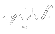
- the object is achieved according to a method for preforming steel wires and in connection with the features in the preamble of claim 1 such that, provided that a 100% accurate and constant drain tension of the steel wire is maintained between the wire spool and the stranding point of a stranding device, depending on the diameter " d 0 "of the steel wire is successively applied to the steel wire to be stranded in certain stages such a force component that, as a result, the steel wire assumes a defined and permanent helical shape, in which the expansion of a screw winding in the axial and radial direction of the desired lay length, as seen in the same" s "and the radial distance of the later layer to the central axis of the later stranding assembly and the wire length of a screw turn corresponds to the actual wire length" I "in the later stranding assembly within the respective layer.
- the helical turn of the steel wire is generated Force component through simultaneous and defined effect of tensile force as well Bending, friction and torsion on the steel wire or on the surface the same to generate.
- Another measure provides that the number and size of the stages successive force components and their spatial distance with each other and to an upstream torsion lock depending on the desired extension of the screw turn of the steel wire is selected.
- the device for preforming steel wires stands out in connection with the features in the preamble of claim 5 from that between the Wire spool of the respective steel wire and the stranding point of the Stranding device seen in the direction of the wire one after the other Torsion lock, consisting of one or more guide roles, as well as one any number of stationary, but adjustable preform pins are provided, the steel wire in one or more turns around the Torsion lock led around as well as a serpentine between the Preform pins in a narrowly defined axial direction of the steel wire itself expanding area of the surface thereof touching the preform pins, is passed through and being to achieve a 100% accurate and constant
- the tension of the steel wire of each wire spool is adjustable Coil brake or a controllable coil drive system is assigned.
- the device is characterized in that the guide rollers of the torsion lock, depending on the diameter "d 0 " of the steel wire, have a diameter "D" such that the steel wire around them experiences just an elastic deformation at the boundary with the plastic and the The number of turns around the guide rollers of the torsion lock is selected so that the existing rotary movement of the steel wire around its longitudinal axis does not run back into the wire payout spool as a result of the actual stranding process.
- preform pins depending on their number and the Force components to be applied to the steel wire exactly in a row or laterally offset from each other at a certain distance.
- the preform pins are made of wear-resistant material with a density of 12-15 g / cm 3 and a surface roughness of 0.15 R Rz 1 1,5 1.5.
- Preform head and possibly several such preform heads depending on the number of layers to be stranded seen in the direction of the steel wires are arranged one after the other.
- each preform head is compact Component is executed or from two or more on a common axis axially arranged one after the other and rotatable separately from each other, however lockable discs, which in turn in a suitable arrangement Guide rollers and / or have a freely selectable number of preform pins.
- the controllable coil brake of the respective wire payout spool includes a dancer control in the form of a brake band coupled to a swivel lever of a dancer roll, which in turn has any number of brake shoes with a friction lining made of polytetrafluoroethylene (PTFE) with wear-reducing additives, and one that is connected to the wire payout spool in a rotationally fixed manner Brake disc, whose chrome-plated, ground and polished brake surface has a surface roughness Rz 2 ⁇ 10.
- PTFE polytetrafluoroethylene
- the control loop of this coil drive system continues from a control device in the form of a converter with analog processing and PID controller and bus connection, an actuator in the form of a 3-phase asynchronous motor with subsequent gear and feedback, consisting of the running steel wire and the detection of the tensile force "Fz" in the form of a Measuring roller and a measuring amplifier, together.
- the main advantages of the invention are seen, in particular, in the fact that a method and a device for preforming steel wires have been created, on the basis of which a defined, always reproducible and constant helical shape is applied to the steel wires according to their position in the stranding assembly or in the finished steel wire strand can.
- the claimed method and the device are furthermore to be regarded as uncomplicated and the technical effort for realizing them to be low.
- FIG. 1 schematically shows a stranding device 1 in the form of a double-twist stranding machine of the OUT-IN type, on which steel wire strands 2 can be produced and which are used, for example, in the tire industry.
- This stranding device 1 essentially comprises the drive stands 3, 4, 5 and 6 in which the rotating systems are each mounted. Between the drive stands 3 and 4, the payout spool 7 for the core wire 8 or the core strand is mounted in a spool frame 9, which in turn is rotatably supported about the central axis of the rotating system via end hollow pins (not shown), but does not rotate during the stranding process due to its own weight.
- a guide roller 15 for the Core wire 8 or the core strand arranged, which in turn with the speed n x around
- the central axis of the rotating system rotates and the core wire 8 or the core strand in free flight curve to a swirl device arranged on the drive stand 4 16 leads.
- the twist device 16 rotates at a speed n ⁇ 2x.
- a further twisting device 17 is located on the downstream drive stand 5 arranged, which in turn with the same speed and in the same direction as the twister 16 rotates.
- the stranding point 18 is arranged in the form of a stranding nipple, which in turn Devices 19 for preforming the arranged and controlled by stationary braked or regulated driven wire spools 20 running out Steel wires 21 for a desired layer stranding are arranged upstream.
- the devices 19 for preforming consist of a so-called torsion lock 22, here in the form of two successive or side-by-side guide rollers 23a and 23b, through which the steel wire 21 is guided in one or more turns.
- the number of turns is selected such that a rotational movement of the steel wire 21 about its longitudinal axis as a result of the stranding process cannot run back into the wire take-up spool 20.
- the diameter "D" of the guide rollers 23a; 23b is selected as a function of the diameter "d 0 " of the steel wire 21 so that the steel wire 21 just undergoes an elastic deformation at the boundary with the plastic one. It should preferably meet the following condition: 50 xd 0 ⁇ D ⁇ 70 xd 0
- the torsion lock 22 in the form of the guide rollers 23a and 23b is followed by any number of stationary preform pins 24a to 24n, between which the steel wire 21 is guided in a serpentine manner.
- the setting dimensions of the device 19 for preforming such as the radial distance "z" from the center of the last guide roller 23b of the torsion lock 22 to the center of the first preform pin 24a, the distance “y 2 " of the last guide roller 23b from the first preform pin 24a, the diameter "d” of the preform pins 24a to 24n and the distance “y 1 " between the individual preform pins 24a to 24n depending on the diameter "d 0 " of the steel wire 21 and the actual wire length "l” of the steel wire 21 in the later, ie finished stranding within the respective position and lay length "s” are selected and should meet the following conditions: D / 2 - 2d 0 ⁇ z ⁇ D / 2 + d 0 / 2nd 5d 0 ⁇ d ⁇ 7d 0 0.9 xl / 3 ⁇ y 1 ⁇ s / 3 y 2 ⁇ 2y 1
- preform pins 24a to 24n which are arranged in a stationary manner per se, are adjustable such that they are either exactly one after the other in a row as shown in FIG. 4 or laterally at a certain distance from one another can be arranged offset (not shown).
- preform pins 24a to 24n have proven themselves in practice for diameters "d 0 " of the steel wire 21 of 0.18 to 0.22 mm.
- the preform pins 24a to 24n are preferably made of wear-resistant material with a density of 12-15 g / cm 3 and a surface roughness of 0.15 ⁇ Rz 1 ⁇ 1.5 manufactured. Hardened steel but also ceramic materials are ideal for this.
- a 100% accurate has proven to be essential for the fulfillment of the task and constant drain voltage of the steel wire 21 between the wire spool 20 and the stranding point 18 of the stranding device 1.
- each wire pay-off spool 20 is provided with a regulated spool brake 25, the spool brake 25 consisting of a known dancer control in the form of a brake band 28 coupled to a pivoting lever 26 of a dancer roll 27, which in turn any number of brake shoes 29 with a friction lining made of polytetrafluoroethylene (PTFE) with wear-reducing additives, such as. B. 20 to 25% carbon and / or certain glass fiber shares, and consists of a rotatably connected to the wire spool 20 brake disc 30, the chromed, ground and polished brake surface has a surface roughness Rz 2 ⁇ 10.
- PTFE polytetrafluoroethylene
- 6 consists of the control device in the form of a converter 31 with analog processing and PID controller as well as bus connection 32, an actuator in the form of a 3-phase asynchronous motor 33 with subsequent gear 34 and the feedback, consisting of the control device in the form of a converter 31 from the running steel wire 21 and the detection of the tensile force "Fz" in the form of a measuring roller 35 and a measuring amplifier 36.
- Each preform head 37 can also be designed as a compact component, the individual preform pins 24a to 24n being adjustable so that they can be laterally offset from one another due to, for example, a large number of threaded holes arranged on the surface of the preform head, not shown but also from two (FIGS. 3 and 4) or a plurality of disks 37b which can be rotated axially one after the other and separated from one another on a common axis 37a, but can be locked; 37c, which in turn have the guide rollers 23a and 23b of the torsion locks 22 and / or a freely selectable number of preform pins 24a to 24n in a suitable arrangement.
- the disks 37b and 37c can each be non-positively locked on the axis 37a by means of a screw 37d.
- the individual layers of steel wires 21 are applied within the stranding point 18, the individual steel wires 21 being drawn off from the decelerated decoilers 7 with 100% accurate and constant drain tension according to the invention and the device 19 for preforming the respective steel wire 21 before entering the stranding point 18 , consisting of the torsion brake 22 and the preform pins 24a to 24n arranged one after the other.
- a force component such as this is successively applied to the respective steel wire 21 by means of the preform pins 24a to 24n, that is to say in certain stages, that the steel wire 21 assumes a defined and permanent helical shape as a result , in which the expansion of a screw turn in the axial and radial direction of the same, the desired lay length "s" and the radial distance of the later position to the central axis of the subsequent stranding assembly, or the finished steel wire strand 2, and the wire length of a screw turn of the actual wire length "I" in the later stranding within the respective situation.
- the number and the size of the force components acting one after the other in stages, as well as the spatial distance between them and to the upstream torsion lock 22, is chosen depending on the desired extent of the screw winding of the steel wire 21 such that "d 0 " for preferred wire diameters within the scope of the previous ones Try the number of preform pins 24a to 24n and, if necessary, the lateral displacement of these to one another and, using the determined special conditions, the suitable distance "y 2 " between the last guide roller 23b of the torsion lock 22 and the first preform pin 24a, the suitable distances "y 1 " between the individual preform pins 24a to 24n and the suitable radial distance "z" from the center of the last guide roller 23b of the torsion lock 22 to the center of the first preform pin 23b.
- the steel wire strand 2 is fed to the take-up spool 11 arranged within the coil frame 10 via the double-disk take-off 12 and any postforming devices 13 that may be provided, which in turn are intended to eliminate any remaining stresses in the steel wire strand 2.
- Double twist stranding machines of the type OUT-IN can be used.
- Double twist stranding machine of the type OUT-IN differs in that the wire spools 20, together with the regulated coil brake 25 or alternatively adjustable coil drive system and the preform head 37 with the arranged devices 19 for preforming the steel wires 21 within the rotating system of the same in a coil frame 40 are swinging.
- the core wire 8 or the core strand is known to be from outside the rotating system arranged take-off spool 7 and withdrawn via so-called parallel flyers 41a and 41b in a free flight curve in the central axis of the rotating system led to stranding point 18.
- the individual Steel wires 21 after passing through their preforming device 19 applied in layers to the core wire 8 or the core strand, the in Wire run direction seen behind the stranding point 18 Twister 42 rotates at twice the speed of flyers 41a and 41b and as a result, the steel wire strand 2 formed by the individual steel wires 21 undergoes a complete stranding, the first and second stranding twists in a stranding point 18 can be combined.
- the steel wire strand 2 which is finished per se, is passed over the two flyers 41a and 41b out of the rotating system to that known per se Double disc trigger 12 and, if necessary, already mentioned above Postforming devices 13 and an overturning device 43 of the Winding spool 11 supplied.
Landscapes
- Ropes Or Cables (AREA)
- Wire Processing (AREA)
- Heat Treatment Of Strip Materials And Filament Materials (AREA)
- Treatment Of Steel In Its Molten State (AREA)
Applications Claiming Priority (2)
| Application Number | Priority Date | Filing Date | Title |
|---|---|---|---|
| DE10014043 | 2000-03-23 | ||
| DE10014043A DE10014043C2 (de) | 2000-03-23 | 2000-03-23 | Verfahren und Vorrichtung zur Vorformung von Stahldrähten |
Publications (3)
| Publication Number | Publication Date |
|---|---|
| EP1136616A2 true EP1136616A2 (fr) | 2001-09-26 |
| EP1136616A3 EP1136616A3 (fr) | 2003-04-23 |
| EP1136616B1 EP1136616B1 (fr) | 2006-08-09 |
Family
ID=7635811
Family Applications (1)
| Application Number | Title | Priority Date | Filing Date |
|---|---|---|---|
| EP01107145A Expired - Lifetime EP1136616B1 (fr) | 2000-03-23 | 2001-03-22 | Procédé et dispositif de préformage de fils en acier |
Country Status (3)
| Country | Link |
|---|---|
| EP (1) | EP1136616B1 (fr) |
| AT (1) | ATE335877T1 (fr) |
| DE (2) | DE10014043C2 (fr) |
Cited By (9)
| Publication number | Priority date | Publication date | Assignee | Title |
|---|---|---|---|---|
| CN102965990A (zh) * | 2012-11-20 | 2013-03-13 | 江阴市华方机电科技有限公司 | 一种新颖无管式钢丝绳捻股机 |
| CN104265786A (zh) * | 2014-09-30 | 2015-01-07 | 贵州钢绳股份有限公司 | 一种用于股绳机的万向联轴器地轴 |
| CN113215844A (zh) * | 2021-05-13 | 2021-08-06 | 朱淑粉 | 一种高强度镀锌钢绞线制造加工工艺 |
| CN114318914A (zh) * | 2020-10-09 | 2022-04-12 | 南通云天绳缆科技有限公司 | 一种捻股机放线张力的在线模拟检测装置及调试方法 |
| CN114561821A (zh) * | 2022-04-28 | 2022-05-31 | 天津市新天钢中兴盛达有限公司 | 一种矿用锚索用超大直径钢绞线及其制造方法 |
| CN116446206A (zh) * | 2023-05-30 | 2023-07-18 | 江苏兴达钢帘线股份有限公司 | 一种高伸长钢帘线变形器、变形设备及变形方法 |
| CN118202112A (zh) * | 2021-11-25 | 2024-06-14 | 米其林集团总公司 | 具有固定的帘线几何形状并具有双模量行为和适应刚度的增强产品 |
| CN118905105A (zh) * | 2024-08-22 | 2024-11-08 | 河北俊坚半导体科技有限公司 | 扭扭棒自动生产装置 |
| CN121578459A (zh) * | 2026-01-27 | 2026-02-27 | 江苏亨通光电股份有限公司 | 一种光纤带成束加工装置及束状结构可卷绕光纤带光缆 |
Families Citing this family (5)
| Publication number | Priority date | Publication date | Assignee | Title |
|---|---|---|---|---|
| DE10154760B4 (de) * | 2001-11-09 | 2007-11-08 | Sket Verseilmaschinenbau Gmbh | Verfahren und Vorrichtung zur Steuerung und Regelung der Zugkraft in strangförmigem Gut |
| DE102008003204B4 (de) | 2008-01-02 | 2019-07-18 | Casar Drahtseilwerk Saar Gmbh | Vorrichtung zur Verformung von Litzen bei deren Verseilung |
| DE102011053240A1 (de) * | 2011-09-02 | 2013-03-07 | Casar Drahtseilwerk Saar Gmbh | Vorrichtung und Verfahren zur Herstellung eines Drahtseils |
| CN112813711B (zh) * | 2019-11-18 | 2022-12-16 | 宝钢金属有限公司 | 一种精确控制钢帘线扭转波动的生产方法及其装置 |
| CN110735341B (zh) * | 2019-11-21 | 2022-01-04 | 山东鲁普科技有限公司 | 化纤单丝与化纤复丝混纺绳索制作装置和制作方法 |
Family Cites Families (5)
| Publication number | Priority date | Publication date | Assignee | Title |
|---|---|---|---|---|
| DE1808120A1 (de) * | 1968-11-09 | 1970-06-04 | Glanzstoff Ag | Verfahren und Vorrichtung zur Herstellung vorgeformter Litzen oder Seile |
| JPS6059188A (ja) * | 1983-09-02 | 1985-04-05 | ブリヂストン・ベカルト・スチ−ル・コ−ド株式会社 | ゴム物品補強用スチ−ルコ−ド |
| EP0231376B1 (fr) * | 1985-06-27 | 1991-10-09 | Nauchno-Proizvodstvennoe Obiedinenie "ELEKTROSIGNAL" | Procede et machine permettant de produire des cordes torsadees |
| DE4337596A1 (de) * | 1993-10-28 | 1995-05-04 | Thaelmann Schwermaschbau Veb | Verfahren und Vorrichtung zur Herstellung von HT- bzw. Ultra-HT-Cord |
| US6016647A (en) * | 1998-05-06 | 2000-01-25 | Tokyo Rope Manufacturing Co., Ltd. | Manufacturing method and apparatus of steel cord for rubber product reinforcement |
-
2000
- 2000-03-23 DE DE10014043A patent/DE10014043C2/de not_active Expired - Fee Related
-
2001
- 2001-03-22 EP EP01107145A patent/EP1136616B1/fr not_active Expired - Lifetime
- 2001-03-22 DE DE50110654T patent/DE50110654D1/de not_active Expired - Lifetime
- 2001-03-22 AT AT01107145T patent/ATE335877T1/de not_active IP Right Cessation
Cited By (10)
| Publication number | Priority date | Publication date | Assignee | Title |
|---|---|---|---|---|
| CN102965990A (zh) * | 2012-11-20 | 2013-03-13 | 江阴市华方机电科技有限公司 | 一种新颖无管式钢丝绳捻股机 |
| CN104265786A (zh) * | 2014-09-30 | 2015-01-07 | 贵州钢绳股份有限公司 | 一种用于股绳机的万向联轴器地轴 |
| CN114318914A (zh) * | 2020-10-09 | 2022-04-12 | 南通云天绳缆科技有限公司 | 一种捻股机放线张力的在线模拟检测装置及调试方法 |
| CN114318914B (zh) * | 2020-10-09 | 2023-03-24 | 江苏芸裕金属制品有限公司 | 一种捻股机放线张力的在线模拟检测装置及调试方法 |
| CN113215844A (zh) * | 2021-05-13 | 2021-08-06 | 朱淑粉 | 一种高强度镀锌钢绞线制造加工工艺 |
| CN118202112A (zh) * | 2021-11-25 | 2024-06-14 | 米其林集团总公司 | 具有固定的帘线几何形状并具有双模量行为和适应刚度的增强产品 |
| CN114561821A (zh) * | 2022-04-28 | 2022-05-31 | 天津市新天钢中兴盛达有限公司 | 一种矿用锚索用超大直径钢绞线及其制造方法 |
| CN116446206A (zh) * | 2023-05-30 | 2023-07-18 | 江苏兴达钢帘线股份有限公司 | 一种高伸长钢帘线变形器、变形设备及变形方法 |
| CN118905105A (zh) * | 2024-08-22 | 2024-11-08 | 河北俊坚半导体科技有限公司 | 扭扭棒自动生产装置 |
| CN121578459A (zh) * | 2026-01-27 | 2026-02-27 | 江苏亨通光电股份有限公司 | 一种光纤带成束加工装置及束状结构可卷绕光纤带光缆 |
Also Published As
| Publication number | Publication date |
|---|---|
| DE10014043A1 (de) | 2001-10-04 |
| EP1136616B1 (fr) | 2006-08-09 |
| DE50110654D1 (de) | 2006-09-21 |
| DE10014043C2 (de) | 2002-03-28 |
| EP1136616A3 (fr) | 2003-04-23 |
| ATE335877T1 (de) | 2006-09-15 |
Similar Documents
| Publication | Publication Date | Title |
|---|---|---|
| DE2934012C2 (fr) | ||
| DE10014043C2 (de) | Verfahren und Vorrichtung zur Vorformung von Stahldrähten | |
| DE1808120A1 (de) | Verfahren und Vorrichtung zur Herstellung vorgeformter Litzen oder Seile | |
| DE69905555T2 (de) | Vorrichtung zum verseilen von mindestens zwei filamenten | |
| EP0851949B1 (fr) | Procede et dispositif pour l'enroulement simultane de plusieurs fils metalliques sur une bobine a plusieurs fils et/ou pour le deroulement simultane des fils d'une bobine a plusieurs fils ainsi enroule, pour un toronnage ulterieur | |
| CH715908A1 (de) | Verfahren zur Herstellung von Garn mit einer Ringspinnmaschine und Ringspinnmaschine. | |
| DE2813966C2 (fr) | ||
| DE602004006430T2 (de) | Verfahren und vorrichtung zur herstellung eines drahtcords | |
| EP0563586B1 (fr) | Procédé et dispositif de fabrication de corde d'acier à haute résistance | |
| EP0725852B1 (fr) | Procede et dispositif de production de cable acier | |
| DE2814773A1 (de) | Vorrichtung zur herstellung von staeben und roehren aus einem bindemittel und einer armierung | |
| DE3004375C2 (fr) | ||
| DE102010051434B4 (de) | Vorrichtung und Verfahren zur Herstellung eines Umwindegarns | |
| EP2669228B1 (fr) | Bobine de fil enroulée ainsi que dispositif et procédé de fabrication de la bobine de fil | |
| DE10012718C1 (de) | Verfahren und Vorrichtung zur Herstellung hochfester und spannungsarmer Stahldrahtlitzen auf Verseilmaschinen | |
| EP0289884B1 (fr) | Procédé et dispositif pour la fabrication de torons en acier à une ou plusieures couches | |
| EP0396068B1 (fr) | Procédé et dispositif pour la fabrication d'un faisceau de fils ou d'un câble | |
| DE19605491A1 (de) | Verfahren sowie Vorrichtung zur SZ-Verseilung langgestreckter Verseilelemente | |
| DE102017205014B4 (de) | Verlitzmaschine, Verfahren zur Herstellung einer Litze und Litze | |
| AT286833B (de) | Verfahren zur herstellung von spannungsfreien seilen oder litzen und schnellverseilmaschine zur durchfuehrung des verfahrens | |
| DE112010002786B4 (de) | Drahtziehvorrichtung und Verfahren zum Herstellen eines Drahts | |
| CH645746A5 (en) | Method and device for the reversed stranding of stranding elements which are difficult to deform, such as heavy-current cable cores | |
| DE3802631A1 (de) | Verfahren zur herstellung von metallischen verseilten erzeugnissen | |
| DE3810532A1 (de) | Verfahren und vorrichtung zum aufwickeln von strangfoermigem gut | |
| DD131943B1 (de) | Doppelschlagverseilmaschine in rohrloser bauart |
Legal Events
| Date | Code | Title | Description |
|---|---|---|---|
| PUAI | Public reference made under article 153(3) epc to a published international application that has entered the european phase |
Free format text: ORIGINAL CODE: 0009012 |
|
| AK | Designated contracting states |
Kind code of ref document: A2 Designated state(s): AT BE CH CY DE DK ES FI FR GB GR IE IT LI LU MC NL PT SE TR |
|
| AX | Request for extension of the european patent |
Free format text: AL;LT;LV;MK;RO;SI |
|
| PUAL | Search report despatched |
Free format text: ORIGINAL CODE: 0009013 |
|
| AK | Designated contracting states |
Designated state(s): AT BE CH CY DE DK ES FI FR GB GR IE IT LI LU MC NL PT SE TR |
|
| AX | Request for extension of the european patent |
Extension state: AL LT LV MK RO SI |
|
| 17P | Request for examination filed |
Effective date: 20030916 |
|
| AKX | Designation fees paid |
Designated state(s): AT BE CH CY DE DK ES FI FR GB GR IE IT LI LU MC NL PT SE TR |
|
| AXX | Extension fees paid |
Extension state: RO Payment date: 20030916 |
|
| GRAP | Despatch of communication of intention to grant a patent |
Free format text: ORIGINAL CODE: EPIDOSNIGR1 |
|
| GRAS | Grant fee paid |
Free format text: ORIGINAL CODE: EPIDOSNIGR3 |
|
| GRAA | (expected) grant |
Free format text: ORIGINAL CODE: 0009210 |
|
| AK | Designated contracting states |
Kind code of ref document: B1 Designated state(s): AT BE CH CY DE DK ES FI FR GB GR IE IT LI LU MC NL PT SE TR |
|
| AX | Request for extension of the european patent |
Extension state: RO |
|
| PG25 | Lapsed in a contracting state [announced via postgrant information from national office to epo] |
Ref country code: IT Free format text: LAPSE BECAUSE OF FAILURE TO SUBMIT A TRANSLATION OF THE DESCRIPTION OR TO PAY THE FEE WITHIN THE PRESCRIBED TIME-LIMIT;WARNING: LAPSES OF ITALIAN PATENTS WITH EFFECTIVE DATE BEFORE 2007 MAY HAVE OCCURRED AT ANY TIME BEFORE 2007. THE CORRECT EFFECTIVE DATE MAY BE DIFFERENT FROM THE ONE RECORDED. Effective date: 20060809 Ref country code: NL Free format text: LAPSE BECAUSE OF FAILURE TO SUBMIT A TRANSLATION OF THE DESCRIPTION OR TO PAY THE FEE WITHIN THE PRESCRIBED TIME-LIMIT Effective date: 20060809 Ref country code: FI Free format text: LAPSE BECAUSE OF FAILURE TO SUBMIT A TRANSLATION OF THE DESCRIPTION OR TO PAY THE FEE WITHIN THE PRESCRIBED TIME-LIMIT Effective date: 20060809 Ref country code: GB Free format text: LAPSE BECAUSE OF FAILURE TO SUBMIT A TRANSLATION OF THE DESCRIPTION OR TO PAY THE FEE WITHIN THE PRESCRIBED TIME-LIMIT Effective date: 20060809 Ref country code: IE Free format text: LAPSE BECAUSE OF FAILURE TO SUBMIT A TRANSLATION OF THE DESCRIPTION OR TO PAY THE FEE WITHIN THE PRESCRIBED TIME-LIMIT Effective date: 20060809 |
|
| REG | Reference to a national code |
Ref country code: GB Ref legal event code: FG4D Free format text: NOT ENGLISH |
|
| REG | Reference to a national code |
Ref country code: CH Ref legal event code: EP |
|
| REG | Reference to a national code |
Ref country code: IE Ref legal event code: FG4D Free format text: LANGUAGE OF EP DOCUMENT: GERMAN |
|
| REF | Corresponds to: |
Ref document number: 50110654 Country of ref document: DE Date of ref document: 20060921 Kind code of ref document: P |
|
| PG25 | Lapsed in a contracting state [announced via postgrant information from national office to epo] |
Ref country code: SE Free format text: LAPSE BECAUSE OF FAILURE TO SUBMIT A TRANSLATION OF THE DESCRIPTION OR TO PAY THE FEE WITHIN THE PRESCRIBED TIME-LIMIT Effective date: 20061109 Ref country code: DK Free format text: LAPSE BECAUSE OF FAILURE TO SUBMIT A TRANSLATION OF THE DESCRIPTION OR TO PAY THE FEE WITHIN THE PRESCRIBED TIME-LIMIT Effective date: 20061109 |
|
| PG25 | Lapsed in a contracting state [announced via postgrant information from national office to epo] |
Ref country code: ES Free format text: LAPSE BECAUSE OF FAILURE TO SUBMIT A TRANSLATION OF THE DESCRIPTION OR TO PAY THE FEE WITHIN THE PRESCRIBED TIME-LIMIT Effective date: 20061120 |
|
| PG25 | Lapsed in a contracting state [announced via postgrant information from national office to epo] |
Ref country code: PT Free format text: LAPSE BECAUSE OF FAILURE TO SUBMIT A TRANSLATION OF THE DESCRIPTION OR TO PAY THE FEE WITHIN THE PRESCRIBED TIME-LIMIT Effective date: 20070109 |
|
| NLV1 | Nl: lapsed or annulled due to failure to fulfill the requirements of art. 29p and 29m of the patents act | ||
| GBV | Gb: ep patent (uk) treated as always having been void in accordance with gb section 77(7)/1977 [no translation filed] |
Effective date: 20060809 |
|
| REG | Reference to a national code |
Ref country code: IE Ref legal event code: FD4D |
|
| EN | Fr: translation not filed | ||
| PLBE | No opposition filed within time limit |
Free format text: ORIGINAL CODE: 0009261 |
|
| STAA | Information on the status of an ep patent application or granted ep patent |
Free format text: STATUS: NO OPPOSITION FILED WITHIN TIME LIMIT |
|
| 26N | No opposition filed |
Effective date: 20070510 |
|
| REG | Reference to a national code |
Ref country code: CH Ref legal event code: PL |
|
| BERE | Be: lapsed |
Owner name: SKET VERSEILMASCHINENBAU G.M.B.H. Effective date: 20070331 |
|
| PG25 | Lapsed in a contracting state [announced via postgrant information from national office to epo] |
Ref country code: BE Free format text: LAPSE BECAUSE OF NON-PAYMENT OF DUE FEES Effective date: 20070331 |
|
| PG25 | Lapsed in a contracting state [announced via postgrant information from national office to epo] |
Ref country code: MC Free format text: LAPSE BECAUSE OF NON-PAYMENT OF DUE FEES Effective date: 20070331 |
|
| PG25 | Lapsed in a contracting state [announced via postgrant information from national office to epo] |
Ref country code: CH Free format text: LAPSE BECAUSE OF NON-PAYMENT OF DUE FEES Effective date: 20070331 Ref country code: LI Free format text: LAPSE BECAUSE OF NON-PAYMENT OF DUE FEES Effective date: 20070331 |
|
| PG25 | Lapsed in a contracting state [announced via postgrant information from national office to epo] |
Ref country code: FR Free format text: LAPSE BECAUSE OF FAILURE TO SUBMIT A TRANSLATION OF THE DESCRIPTION OR TO PAY THE FEE WITHIN THE PRESCRIBED TIME-LIMIT Effective date: 20070511 Ref country code: GR Free format text: LAPSE BECAUSE OF FAILURE TO SUBMIT A TRANSLATION OF THE DESCRIPTION OR TO PAY THE FEE WITHIN THE PRESCRIBED TIME-LIMIT Effective date: 20061110 |
|
| PG25 | Lapsed in a contracting state [announced via postgrant information from national office to epo] |
Ref country code: AT Free format text: LAPSE BECAUSE OF NON-PAYMENT OF DUE FEES Effective date: 20070322 |
|
| PG25 | Lapsed in a contracting state [announced via postgrant information from national office to epo] |
Ref country code: FR Free format text: LAPSE BECAUSE OF FAILURE TO SUBMIT A TRANSLATION OF THE DESCRIPTION OR TO PAY THE FEE WITHIN THE PRESCRIBED TIME-LIMIT Effective date: 20060809 |
|
| PG25 | Lapsed in a contracting state [announced via postgrant information from national office to epo] |
Ref country code: CY Free format text: LAPSE BECAUSE OF FAILURE TO SUBMIT A TRANSLATION OF THE DESCRIPTION OR TO PAY THE FEE WITHIN THE PRESCRIBED TIME-LIMIT Effective date: 20060809 Ref country code: LU Free format text: LAPSE BECAUSE OF NON-PAYMENT OF DUE FEES Effective date: 20070322 |
|
| PG25 | Lapsed in a contracting state [announced via postgrant information from national office to epo] |
Ref country code: TR Free format text: LAPSE BECAUSE OF FAILURE TO SUBMIT A TRANSLATION OF THE DESCRIPTION OR TO PAY THE FEE WITHIN THE PRESCRIBED TIME-LIMIT Effective date: 20060809 |
|
| PGFP | Annual fee paid to national office [announced via postgrant information from national office to epo] |
Ref country code: DE Payment date: 20110309 Year of fee payment: 11 |
|
| PGFP | Annual fee paid to national office [announced via postgrant information from national office to epo] |
Ref country code: IT Payment date: 20110331 Year of fee payment: 11 |
|
| REG | Reference to a national code |
Ref country code: DE Ref legal event code: R119 Ref document number: 50110654 Country of ref document: DE Effective date: 20121002 |
|
| PG25 | Lapsed in a contracting state [announced via postgrant information from national office to epo] |
Ref country code: IT Free format text: LAPSE BECAUSE OF NON-PAYMENT OF DUE FEES Effective date: 20120322 |
|
| PG25 | Lapsed in a contracting state [announced via postgrant information from national office to epo] |
Ref country code: DE Free format text: LAPSE BECAUSE OF NON-PAYMENT OF DUE FEES Effective date: 20121002 |