EP1136621A2 - Rotary roller - Google Patents
Rotary roller Download PDFInfo
- Publication number
- EP1136621A2 EP1136621A2 EP01102926A EP01102926A EP1136621A2 EP 1136621 A2 EP1136621 A2 EP 1136621A2 EP 01102926 A EP01102926 A EP 01102926A EP 01102926 A EP01102926 A EP 01102926A EP 1136621 A2 EP1136621 A2 EP 1136621A2
- Authority
- EP
- European Patent Office
- Prior art keywords
- deflecting
- roll according
- roller
- deflection
- medium
- Prior art date
- Legal status (The legal status is an assumption and is not a legal conclusion. Google has not performed a legal analysis and makes no representation as to the accuracy of the status listed.)
- Granted
Links
Images



Classifications
-
- F—MECHANICAL ENGINEERING; LIGHTING; HEATING; WEAPONS; BLASTING
- F28—HEAT EXCHANGE IN GENERAL
- F28F—DETAILS OF HEAT-EXCHANGE AND HEAT-TRANSFER APPARATUS, OF GENERAL APPLICATION
- F28F5/00—Elements specially adapted for movement
- F28F5/02—Rotary drums or rollers
-
- D—TEXTILES; PAPER
- D21—PAPER-MAKING; PRODUCTION OF CELLULOSE
- D21G—CALENDERS; ACCESSORIES FOR PAPER-MAKING MACHINES
- D21G1/00—Calenders; Smoothing apparatus
- D21G1/02—Rolls; Their bearings
- D21G1/0253—Heating or cooling the rolls; Regulating the temperature
- D21G1/0266—Heating or cooling the rolls; Regulating the temperature using a heat-transfer fluid
-
- F—MECHANICAL ENGINEERING; LIGHTING; HEATING; WEAPONS; BLASTING
- F16—ENGINEERING ELEMENTS AND UNITS; GENERAL MEASURES FOR PRODUCING AND MAINTAINING EFFECTIVE FUNCTIONING OF MACHINES OR INSTALLATIONS; THERMAL INSULATION IN GENERAL
- F16C—SHAFTS; FLEXIBLE SHAFTS; ELEMENTS OR CRANKSHAFT MECHANISMS; ROTARY BODIES OTHER THAN GEARING ELEMENTS; BEARINGS
- F16C13/00—Rolls, drums, discs, or the like; Bearings or mountings therefor
-
- F—MECHANICAL ENGINEERING; LIGHTING; HEATING; WEAPONS; BLASTING
- F16—ENGINEERING ELEMENTS AND UNITS; GENERAL MEASURES FOR PRODUCING AND MAINTAINING EFFECTIVE FUNCTIONING OF MACHINES OR INSTALLATIONS; THERMAL INSULATION IN GENERAL
- F16C—SHAFTS; FLEXIBLE SHAFTS; ELEMENTS OR CRANKSHAFT MECHANISMS; ROTARY BODIES OTHER THAN GEARING ELEMENTS; BEARINGS
- F16C2300/00—Application independent of particular apparatuses
- F16C2300/02—General use or purpose, i.e. no use, purpose, special adaptation or modification indicated or a wide variety of uses mentioned
Definitions
- the invention relates to a rotatable roller with a roller body, the channels are assigned to the passage of a medium, according to the preamble of the claim 1 or 6
- rollers can be found in many areas of application, for example in the production of paper, in the food industry and in rolling processes of plastic or steel, for example in continuous casting using continuous casting. It is known here, roller body with, for example, axial, just below the surface running channels for their temperature control, for example heating Mistake. Such a roller can be seen, for example, from EP 0 606 660 A1.
- the invention is based on the problem of achieving an improvement here.
- the invention solves this problem by means of a roller with the features of the claim 1 or 6 and a deflector with the features of the claim 24.
- Advantageous embodiments of the invention are in claims 2 to 5, 7 to 23 and 25 specified.
- the provision of separators makes the medium flow smaller Cross section provided in the channel, so that the speed of the Temperature control medium increased, which ensures a better temperature transition is.
- the channel divided in this way simultaneously e.g. as pre and Return for the temperature control medium can serve.
- a third or quarter is an advantage.
- the separating body is in the form of a has multi-start spiral, so that only by the winding a swirl of the temperature control medium.
- the length of stay of Temperature control medium is higher due to the larger distance to be covered. The Whirling, increasing the length of stay and increasing the speed due to the narrowing of the duct, optimal heat transfer occurs.
- the inventive design of a roller according to claim 6 is a deviation the flow of laminarity guaranteed. There is one Turbulence with which the flow through the channels of the roller per unit of time Volume of temperature control medium is reduced. This results in a Saving heating fluid, for example. At the same time is the heat transfer improved to the roller, however, a larger proportion of the heating medium comes into contact with the walls of the channels.
- the deflection area can spread over a large longitudinal portion of the channel. The heat transfer is then great Longitudinal area of the channel improved. If the deflection area is arranged, at least in the outer area of the deflector, is in the area that the channel walls is adjacent, the swirl is reached. The efficiency is thereby particularly good.
- the deflector can have a rigid longitudinal axis as well as overall, for example in the manner of a coil spring Form the deflection area.
- the separating body and deflecting body in one Channel are used, the separating body as a carrier for the deflector can serve.
- a roller according to the invention has one or several axially and distributed over the circumference in the roller Flow channels 1, 101, 201, 301, 501, 601 for a medium, in particular a liquid for tempering the roller.
- Flow channels 1, 101, 201, 301, 501, 601 for a medium, in particular a liquid for tempering the roller can, for example be made by drilling and then a straight line to have.
- several such channels are arranged in a roller his.
- Such a roller body is configured on both sides with flange pins, by means of which the channels are also connected to an external supply Heating or cooling medium is ensured.
- a central, axial hollow area is at a hollow roller (Fig.
- a flow channel 401 for the temperature control medium usable this channel 401, for example, as an outgoing line and a peripheral Channel 1, 101, 201, 301, 501, 601 can serve as a return line or vice versa.
- the central flow channel 401 can be used to better coordinate the flow conditions also be provided with a deflector 405, which in its dimensions adapted to the axial and radial extension of the cavity is.
- a straight channel 1 is shown, which is on a roller side an inlet E and on the other side an outlet A for the flow Medium.
- a channel 101 is shown, the Inlet E and outlet A on the same side of the roll surrounding the channel lie.
- two deflections 202 are formed, so that inlet side E and outlet side A of channel 201 are on opposite sides Sides of the roller.
- FIG. 6d there are three deflections 302 provided so that inlet E and outlet A of such a channel 301 again lie on the same side of the roller body. All such channels 1, 101, 201, 301 penetrate the roller body preferably over its axial extent essentially or completely.
- the channel 501 is designed in such a way that two external input lines E lead to a central outlet line A.
- the number of inlet and outlet openings E, A is therefore different.
- the channel 601 according to FIG. 7c has three inlet openings E and one outlet opening A so that the number of inflow openings and Outflow openings E, A is different.
- a deflector 5 which has a longitudinal dimension L parallel has to its longitudinal axis 6.
- the deflecting body 5 comprises a deflecting area 7, which is designed as a worm orbiting the longitudinal axis 6, and opposite the longitudinal axis 6 is inclined.
- the deflection areas 7 are at an acute angle to the walls 1a of channel 1, 101, 201, 301, 501, 601.
- the deflecting body 5, 105 according to FIG. 2 comprises a rigid central axis 106, around which the inclined and helically formed Deflection areas 107 extend.
- the deflection areas can be of the type Snail coherent over the entire longitudinal course L of the deflecting body 105 be formed, or it can be individual inclined deflection areas 107 be present.
- the deflection body 205 is as a whole helical spring-like body formed so that the longitudinal axis 6 only of the deflection areas 207 is surrounded.
- FIGS. 3 and 5 show a deflecting body 205 when used in a channel 1 or 101, for example, in the roll body of a roll that can be heated a wooden cylindrical roller is arranged.
- a deflecting body 205 when used in a channel 1 or 101, for example, in the roll body of a roll that can be heated a wooden cylindrical roller is arranged.
- there are Channels 1, 101 as well as the channels of the other exemplary embodiments are sealed underneath the outer roller surface in order to be as effective as possible To enable heating process.
- All of the deflection bodies 5, 105, 205, 405 shown form one in the heating medium turbulent flow, so that the individual flowing particles a longer Path in channel 1, 101, 201, 301, 401, 501, 601 have to be covered and therefore the length of stay - and therefore also the energy transmission time - is increased. This effect remains even with a selectively increased flow rate Particles of the medium are preserved as it is triggered by the turbulence can.
- Deflection bodies 5, 105, 205, 405 with such - may not dimensionally stable, but to be shaped by the flowing medium - deflection areas 7, 107, 207, 407 possible that a chaotic flow of the Medium is effected. This can change over time or when the pressure changes change from passed medium.
- a spring-like or other deformable deflector 205 can be the slope of the deflection regions 207 or the length L of the deflection body if necessary during the operation to be varied, so that the type of Turbulence and the possibly additionally formed rotation influence too and so the parameters flow rate, amount of liquid to be introduced, or the amount of gas, residence time and turbulence of the medium introduced to be able to influence.
- the gradient of the deflection area 7, 107, 207, 407 can vary, so that areas 7a with a smaller slope and areas 7b with a larger slope available. Areas with the same or different slope 7a, 7b can also be spatially spaced from one another.
- FIG. 9 shows a separating body 50 in the form of a two-start helix 70 as it is can be used in a channel.
- the flow of the temperature control medium can in one coil and the reverse flow of the temperature control medium in the second spiral.
- the return and return can be done in one channel be provided.
- FIG. 9 shows that the helix angle of the helix, both for the outward line of temperature control medium are used continuously in the direction of flow downsized.
- the path for the temperature control medium becomes longer, the dwell time bigger and the speed has to be increased accordingly so that a better heat transfer is made possible.
- FIG. 10 shows a separating body 50 which at the same time is in one piece the deflecting body having. These are arranged completely arbitrarily in a partial area of the channel. In the second section, the deflection bodies are continuously changing Incline provided.
- the deflection bodies 5, 105, 205, 405 shown and the separating bodies can also have any other shape. They are subsequently in channels 1, 101, 201, 301, 401, 501, 601, can be used. This makes installation easier. Conventional rollers can also be converted in this way.
- deflection areas 7, 107, 207, 407 as in the exemplary embodiments shown, set the medium in rotation. However, this allows an even and predictable sequence of turbulent flows in the channel of the roller to be tempered.
- the deflecting bodies 5, 105, 205, 405 and or separating bodies can, depending on the one used Medium can be formed from different materials, for example made of stainless steel or plastic, provided that corrosive media are used.
Landscapes
- Engineering & Computer Science (AREA)
- General Engineering & Computer Science (AREA)
- Mechanical Engineering (AREA)
- Physics & Mathematics (AREA)
- Thermal Sciences (AREA)
- Rolls And Other Rotary Bodies (AREA)
- Continuous Casting (AREA)
- Footwear And Its Accessory, Manufacturing Method And Apparatuses (AREA)
Abstract
Eine rotierbare Walze mit einem Walzenkörper, dem Kanäle zur Durchleitung eines
zur Temperaturregelung des Walzenkörpers dienenden Mediums, insbesondere
einer Flüssigkeit, zugeordnet sind, soll so aufgebaut werden, daß ein besserer
Wärmeübergang vom Medium in den Walzenkörper erreicht wird. Dazu wird
zumindest ein in einen der Kanäle einbringbarer und auf das Medium einwirkender
Trennkörper und/oder Ablenkkörper vorgeschlagen, der in Einbaustellung zumindest
bereichsweise einen gegenüber einem Wandungsbereich des Kanals spitzwinklig
angestellten Ablenkbereich umfaßt.
Description
Die Erfindung betrifft eine rotierbare Walze mit einem Walzenkörper, dem Kanäle
zur Durchleitung eines Mediums zugeordnet sind, nach dem Oberbegriff des Anspruchs
1 bzw. 6The invention relates to a rotatable roller with a roller body, the channels
are assigned to the passage of a medium, according to the preamble of the
Derartige Walzen finden sich in vielerlei Anwendungsbereichen, beispielsweise in der Herstellung von Papier, in der Lebensmittelindustrie sowie bei Walzvorgängen von Kunststoff oder Stahl, etwa beim Gießwalzen im Stranggießverfahren. Es ist hierbei bekannt, Walzenkörper mit beispielsweise axialen, dicht unter der Oberfläche verlaufenden Kanälen zu ihrer Temperierung, beispielsweise Beheizung, zu versehen. Eine derartige Walze geht beispielsweise aus der EP 0 606 660 A1 hervor.Such rollers can be found in many areas of application, for example in the production of paper, in the food industry and in rolling processes of plastic or steel, for example in continuous casting using continuous casting. It is known here, roller body with, for example, axial, just below the surface running channels for their temperature control, for example heating Mistake. Such a roller can be seen, for example, from EP 0 606 660 A1.
Bei parallelwandigen Kanälen, wie sie durch Bohrungen herstellbar sind, zur Durchleitung des Mediums, insbesondere einer Heizflüssigkeit, ist bei einer laminaren Strömung ein hoher Bedarf an Heizmedium erforderlich. Zudem geben nur die äußeren Bereiche des Strömungsprofils hinreichend Wärme an die Wandungen des Kanals, und damit an die Walze, ab. Innen liegende Strömungsfäden behalten zum größten Teil ihre Wärmeenergie, was den Wirkungsgrad verschlechtert. For parallel-walled channels, such as those that can be produced through bores, for Passage of the medium, in particular a heating liquid, is a laminar one Flow requires a high demand for heating medium. Also give only the outer areas of the airfoil have sufficient heat on the walls of the channel, and thus to the roller. Internal flow threads retain their thermal energy for the most part, which worsens efficiency.
Der Erfindung liegt das Problem zugrunde, hier eine Verbesserung zu erreichen.The invention is based on the problem of achieving an improvement here.
Die Erfindung löst dieses Problem durch eine Walze mit den Merkmalen des Anspruchs
1 oder 6 sowie einem Ablenkkörper mit den Merkmalen des Anspruchs
24. Vorteilhafte Ausgestaltungen der Erfindung sind in den Ansprüchen 2 bis 5, 7
bis 23 und 25 angegeben.The invention solves this problem by means of a roller with the features of the
Durch das Vorsehen von Trennkörpern wird dem Mediumstrom ein kleinerer Querschnitt im Kanal zur Verfügung gestellt, so daß sich die Geschwindigkeit des Temperiermediums erhöht, wodurch ein besserer Temperaturübergang gewährleistet ist. Hinzu kommt, daß der so geteilte Kanal gleichzeitig z.B. als Vor- und Rücklauf für das Temperiermedium dienen kann. Hier ist eine Halbierung des Kanals, eine Drittelung oder Viertelung von Vorteil. Noch größere Teilungen sind ebenfalls denkbar. Besonders vorteilhaft ist, wenn der Trennkörper die Form einer mehrgängigen Wendel aufweist, so daß allein durch die Wendelung eine Verwirbelung des Temperiermediums erfolgt. Hinzu kommt, daß die Verweildauer des Temperiermediums durch den größeren zurückzulegenden Weg höher ist. Die Verwirbelung, die Erhöhung der Verweildauer und die Geschwindigkeitserhöhung durch die Kanaleinengung bewirken einen optimalen Wärmeübergang.The provision of separators makes the medium flow smaller Cross section provided in the channel, so that the speed of the Temperature control medium increased, which ensures a better temperature transition is. In addition, the channel divided in this way simultaneously e.g. as pre and Return for the temperature control medium can serve. Here is a halving of the canal, a third or quarter is an advantage. There are even larger divisions also conceivable. It is particularly advantageous if the separating body is in the form of a has multi-start spiral, so that only by the winding a swirl of the temperature control medium. In addition, the length of stay of Temperature control medium is higher due to the larger distance to be covered. The Whirling, increasing the length of stay and increasing the speed due to the narrowing of the duct, optimal heat transfer occurs.
Durch die erfindungsgemäße Ausbildung einer Walze nach Anspruch 6 ist ein Abweichen der Durchströmung von der Laminarität gewährleistet. Es ergibt sich eine Turbulenz, mit der das pro Zeiteinheit den oder die Kanäle der Walze durchströmende Volumen von Temperiermedium verringert wird. Dadurch ergibt sich eine Einsparung an beispielsweise Heizflüssigkeit. Gleichzeitig ist der Wärmeübergang zur Walze jedoch verbessert, ein größerer Anteil des Heizmediums tritt in Kontakt mit den Wandungen der Kanäle. The inventive design of a roller according to claim 6 is a deviation the flow of laminarity guaranteed. There is one Turbulence with which the flow through the channels of the roller per unit of time Volume of temperature control medium is reduced. This results in a Saving heating fluid, for example. At the same time is the heat transfer improved to the roller, however, a larger proportion of the heating medium comes into contact with the walls of the channels.
Wenn der Ablenkkörper einen in Einbaustellung der Kanalrichtung folgende Längsausdehnung hat, kann der Ablenkbereich sich über einen großen Längsanteil des Kanals erstrecken. Der Wärmeübergang ist dann über einen großen Längsbereich des Kanals verbessert. Bei Anordnung des Ablenkbereiches, zumindest im Außenbereich des Ablenkkörpers, ist im Gebiet, das den Kanalwandungen benachbart ist, die Verwirbelung erreicht. Der Wirkungsgrad ist dadurch besonders gut. Dabei kann der Ablenkkörper sowohl eine starre Längsachse haben als auch insgesamt, beispielsweise nach Art einer Schraubenfeder, einen Ablenkbereich ausbilden.If the deflector follows one in the installed position in the direction of the duct Longitudinal expansion, the deflection area can spread over a large longitudinal portion of the channel. The heat transfer is then great Longitudinal area of the channel improved. If the deflection area is arranged, at least in the outer area of the deflector, is in the area that the channel walls is adjacent, the swirl is reached. The efficiency is thereby particularly good. The deflector can have a rigid longitudinal axis as well as overall, for example in the manner of a coil spring Form the deflection area.
Eine besonders günstige Konstellation ergibt sich, wenn der Ablenkbereich das umströmende Medium in Rotation versetzt, was beispielsweise durch eine der Längsachse folgende spiralförmige Gestalt des Ablenkkörpers erreicht werden kann.A particularly favorable constellation arises when the deflection area flowing medium is set in rotation, for example by one of the Longitudinal axis following spiral shape of the deflector can be achieved can.
Wenn die Ablenkbereiche über den axialen Verlauf des Ablenkkörpers variierende Steigungen aufweisen, können Walzenbereiche gezielt mit unterschiedlicher Intensität vom Temperiermedium beaufschlagt werden.When the deflection areas vary over the axial course of the deflection body Roll areas can selectively with different intensities be acted upon by the temperature control medium.
Ein besonderer Vorteil ergibt sich, wenn die Trennkörper und Ablenkkörper in einen Kanal eingesetzt werden, wobei die Trennkörper als Träger für die Ablenkkörper dienen können.A particular advantage results when the separating body and deflecting body in one Channel are used, the separating body as a carrier for the deflector can serve.
Weitere Vorteile und Merkmale ergeben sich aus in der Zeichnung dargestellten Ausführungsbeispielen des Gegenstandes der Erfindung.Further advantages and features emerge from the drawing Embodiments of the subject of the invention.
In der Zeichnung zeigt:
Figur 1- einen Ablenkkörper, der insgesamt schneckenförmig ausgebildet ist,
- Figur 2
- einen ähnlichen Ablenkkörper wie
Figur 1, bei dem eine starre mittige Längsachse vorgesehen ist, auf dem außenseitig eine Schnecke angeordnet ist, - Figur 3
- einen gradlinigen Heizkanal, der beispielsweise als Bohrung in einem Walzenkörper ausgebildet sein kann,
- Figur 4
- einen insgesamt nach Art einer Schraubenfeder ausgebildeten Ablenkkörper,
Figur 5- einen Heizkanal, der eine Umlenkung um 180° aufweist und bei dem Einlaß- und Ausströmöffnung auf der gleichen Walzenseite liegen,
- Figur 6a
- eine Parallelanordnung mehrerer sogenannter Monopasskanäle,
- Figur 6b
- eine Duopassanordnung, bei der Einström- und Auslaßöffnung auf einer Seite liegen,
- Figur 6c
- eine Tripassanordnung, bei der zwei Umlenkungen ausgebildet sind,
- Figur 6d
- eine Quatropassanordnung, bei der ein Kanal drei Umlenkungen um jeweils 180° unterworfen ist,
Figur 7a- eine Anordnung, bei der zwei Einlaßöffnungen in eine Auslaßöffnung münden,
- Figur 7b
- eine umgekehrte Anordnung, bei der eine Einlaßöffnung in zwei Auslaßöffnungen mündet,
- Figur 7c
- eine Anordnung, bei der drei Einlaßöffnungen in eine Ausströmöffnung münden,
- Figur 8
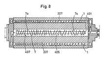
- eine schematische Schnittdarstellung einer Walze mit einem zentralen, als Durchströmkanal für Temperierungsmedium genutzten Hohlraum, in den ein Ablenkkörper eingesetzt ist,
- Figur 9
- einen Trennkörper in der Form einer zweigängigen Wendel, wobei sich der Steigungswinkel der Wendel in Strömungsrichtung kontinuierlich verkleinert, und
- Figur 10
- einen Trennkörper der gleichzeitig Ablenkkörper aufweist.
- Figure 1
- a deflecting body, which is generally helical,
- Figure 2
- a deflection body similar to FIG. 1, in which a rigid central longitudinal axis is provided, on the outside of which a screw is arranged,
- Figure 3
- a straight-line heating duct, which can be designed, for example, as a bore in a roller body,
- Figure 4
- a deflector body designed overall in the manner of a coil spring,
- Figure 5
- a heating duct which has a deflection of 180 ° and which is on the same roll side at the inlet and outlet opening,
- Figure 6a
- a parallel arrangement of several so-called monopass channels,
- Figure 6b
- a duo pass arrangement in which the inlet and outlet openings are on one side,
- Figure 6c
- a tripass arrangement in which two deflections are formed,
- Figure 6d
- a quatropass arrangement in which a channel is subjected to three deflections by 180 °,
- Figure 7a
- an arrangement in which two inlet openings open into one outlet opening,
- Figure 7b
- a reverse arrangement in which an inlet opening opens into two outlet openings,
- Figure 7c
- an arrangement in which three inlet openings open into an outflow opening,
- Figure 8
- 2 shows a schematic sectional illustration of a roller with a central cavity used as a flow channel for the temperature control medium, into which a deflection body is inserted,
- Figure 9
- a separating body in the form of a two-start helix, the helix angle of the helix continuously decreasing in the direction of flow, and
- Figure 10
- a separating body which also has deflection bodies.
Im einzelnen weist eine erfindungsgemäße Walze (gezeichnet in Fig. 8) einen
oder mehrere sich axial und über den Umfang in der Walze verteilt angeordnete
Durchströmungskanäle 1, 101, 201, 301, 501, 601 für ein Medium, insbesondere
eine Flüssigkeit, zur Temperierung der Walze auf. Derartige Kanäle können beispielsweise
durch Bohrungen angefertigt sein und dann einen gradlinigen Verlauf
haben. In aller Regel werden mehrere derartiger Kanäle in einer Walze angeordnet
sein. Ein derartiger Walzenkörper ist beidseitig mit Flanschzapfen ausgestaltet,
mittels denen auch ein Anschluß der Kanäle zu einer äußeren Versorgung mit
Heiz- oder Kühlmedium sichergestellt ist. Ein zentraler, axialer Hohlbereich ist bei
einer Hohlwalze (Fig. 8) als Durchströmkanal 401 für Temperierungsmedium
nutzbar, wobei dieser Kanal 401 beispielsweise als Hinleitung und ein peripherer
Kanal 1, 101, 201, 301, 501, 601 als Rücklaufleitung dienen kann oder umgekehrt.
Der zentrale Durchströmkanal 401 kann zur besseren Abstimmung der Strömungsverhältnisse
ebenfalls mit einem Ablenkkörper 405 versehen sein, der in
seinen Ausmaßen an die axiale und radiale Erstreckung des Hohlraums angepasst
ist.In particular, a roller according to the invention (shown in FIG. 8) has one
or several axially and distributed over the circumference in the
In Figur 3 ist ein gradlinig verlaufender Kanal 1 gezeigt, der auf einer Walzenseite
einen Einlaß E und auf der anderen Seite einen Auslaß A für das durchströmende
Medium aufweist.In Figure 3, a
In einem weiteren Ausführungsbeispiel (Figur 5) ist ein Kanal 101 dargestellt, dessen
Einlaß E und Auslaß A auf derselben Seite der den Kanal umgebenden Walze
liegen. Gegenüber von Ein- und Auslaß befindet sich ein axialer Endbereich 102,
in dem eine Umlenkung des Kanals 101 um 180° ausgebildet ist, wodurch sich die
zur Auslaßseite A ergebende Rückführung 103 ausbildet.In a further exemplary embodiment (FIG. 5), a
Gemäß dem Ausführungsbeispiel nach Figur 6c sind zwei Umlenkungen 202 ausgebildet,
so daß Einlaßseite E und Auslaßseite A des Kanals 201 auf gegenüberliegenden
Seiten der Walze liegen. Nach Figur 6d sind drei Umlenkungen 302
vorgesehen, so daß Einlaß E und Auslaß A eines derartigen Kanals 301 wieder
auf der selben Seite des Walzenkörpers liegen. Alle derartigen Kanäle 1, 101,
201, 301 durchdringen den Walzenkörper über seine axiale Erstreckung bevorzugt
im wesentlichen oder vollständig.According to the exemplary embodiment according to FIG. 6c, two
Der Kanal 501 ist derartig ausgebildet, daß zwei außen liegende Eingangsleitungen
E zu einer mittigen Ausgangsleitung A führen. Die Anzahl von Ein- und Ausströmöffnungen
E, A ist daher unterschiedlich. Gleiches gilt auch für das Kanalsystem
nach Figur 7b, bei dem Eingangs- und Ausströmöffnungen vertauscht wurden.
Der Kanal 601 nach Figur 7c weist drei Eingangsöffnungen E und eine Ausgangsöffnung
A auf, so daß auch hier die Anzahl von Einströmöffnungen und
Ausströmöffnungen E, A unterschiedlich ist. The
In Figur 1 ist ein Ablenkkörper 5 dargestellt, der eine Längsausdehnung L parallel
zu seiner Längsachse 6 aufweist. Der Ablenkkörper 5 umfaßt einen Ablenkbereich
7, der als die Längsachse 6 umlaufende Schnecke ausgebildet ist, und gegenüber
der Längsachse 6 schräg angestellt ist. Bei Einbaustellung in einen Kanal 1, 101,
201, 301, 501, 601 sind die Ablenkbereiche 7 spitzwinklig gegenüber den Wandungen
1a des Kanals 1, 101, 201, 301, 501, 601 angestellt.In Figure 1, a
Der Ablenkkörper 5, 105 nach Figur 2 umfaßt eine starr ausgebildete Mittelachse
106, um die herum sich die schräg angestellten und wendelförmig ausgebildeten
Ablenkbereiche 107 erstrecken. Die Ablenkbereiche können nach Art einer
Schnecke über den gesamten Längsverlauf L des Ablenkkörpers 105 zusammenhängend
ausgebildet sein, oder es können einzelne schräg gestellte Ablenkbereiche
107 vorhanden sein.The deflecting
Gemäß einem dritten Ausführungsbeispiel ist der Ablenkkörper 205 insgesamt als
schraubenfederartiger Körper ausgebildet, so daß die Längsachse 6 lediglich von
den Ablenkbereichen 207 umgeben ist.According to a third exemplary embodiment, the
Die Figuren 3 und 5 zeigen einen Ablenkkörper 205 bei Einsatz in einen Kanal 1
bzw. 101, der in dem Walzenkörper einer temperierbaren Walze, beispielsweise
einer holzylindrischen Walze, angeordnet ist. Wie oben beschrieben, liegen derartige
Kanäle 1, 101 wie auch die Kanäle der weiteren Ausführungsbeispiele dicht
unterhalb der äußeren Walzenoberfläche, um damit einen möglichst effektiven
Heizvorgang zu ermöglichen.FIGS. 3 and 5 show a deflecting
Sämtliche gezeigten Ablenkkörper 5, 105, 205, 405 bilden im Heizmedium eine
turbulente Strömung aus, so daß die einzelnen strömenden Teilchen einen längeren
Weg im Kanal 1, 101, 201, 301, 401, 501, 601 zurückzulegen haben und daher
die Verweildauer - mithin auch die Energieübertragungszeit - vergrößert ist.
Dieser Effekt bleibt auch bei einer punktuell vergrößerten Fließgeschwindigkeit der
Teilchen des Mediums erhalten, wie es durch die Turbulenzen ausgelöst werden
kann. Auch sind Ablenkkörper 5, 105, 205, 405 mit derartigen - eventuell nicht
formstabilen, sondern durch das anströmende Medium zu formenden - Ablenkbereichen
7, 107, 207, 407 möglich, daß dadurch eine chaotische Strömung des
Mediums bewirkt ist. Diese kann sich im Zeitverlauf oder bei Änderung des Drucks
von durchgeleitetem Medium ändern.All of the
Bei Verwendung eines federähnlichen oder anders deformierbaren Ablenkkörpers
205 kann die Steigung der Ablenkbereiche 207 oder die Länge L des Ablenkkörpers
gegebenenfalls während die Betriebes variiert werden, um damit die Art der
Turbulenzen und die eventuell zusätzlich ausgebildete Rotation beeinflussen zu
können und so die Parameter Fließgeschwindigkeit, einzubringende Flüssigkeitsmenge,
bzw. Gasmenge, Verweildauer und Turbulenz des eingebrachten Mediums
beeinflussen zu können. Über den axialen Verlauf eines Ablenkkörpers 5,
105, 205, 405 kann die Steigung des Ablenkbereichs 7, 107, 207, 407 variieren,
so daß Bereiche 7a mit geringerer Steigung und Bereiche 7b mit größerer Steigung
vorhanden sind. Bereiche mit gleicher oder unterschiedlicher Steigung 7a,
7b können zudem räumlich zueinander beabstandet sein.When using a spring-like or other
Figur 9 zeigt einen Trennkörper 50 in Form einer zweigängigen Wendel 70, wie er
in einen Kanal eingesetzt werden kann. Dabei kann der Hinstrom des Temperiermediums
in der einen Wendel und der Rückstrom des Temperiermediums in der
zweiten Wendel erfolgen. Dabei kann die Hin- und Rückführung in einem Kanal
vorgesehen sein. Es besteht jedoch auch die Möglichkeit, dass die Hinführung des
Temperiermediums in einer Wendel eines Kanals und die Rückführung dieses
Temperiermediums in einer Wendel eines anderen Kanals erfolgt. Es besteht auch
durchaus die Möglichkeit, beide Wendel eines Kanals mit dem hinfließenden bzw.
hinströmenden Temperiermedium zu speisen, wobei sogar unterschiedliche Temperiermedien,
d. h. unterschiedlich in Konsistenz und/oder Temperatur und/oder
Geschwindigkeit eingespeist werden können. FIG. 9 shows a separating
Die Figur 9 zeigt, dass sich der Steigungswinkel der Wendel, die beide zur Hinleitung von Temperiermedium verwendet werden, in Strömungsrichtung kontinuierlich verkleinert. Damit wird der Weg für das Temperiermedium länger, die Verweilzeit größer und die Geschwindigkeit muss entsprechend erhöht werden, so dass ein besserer Wärmeübergang ermöglicht wird.FIG. 9 shows that the helix angle of the helix, both for the outward line of temperature control medium are used continuously in the direction of flow downsized. The path for the temperature control medium becomes longer, the dwell time bigger and the speed has to be increased accordingly so that a better heat transfer is made possible.
Die Figur 10 zeigt einen Trennkörper 50, der gleichzeitig Ablenkkörper einstückig
aufweist. Diese sind in einem Teilbereich des Kanals vollkommen beliebig angeordnet.
Im zweiten Teilbereich sind die Ablenkkörper mit sich kontinuierlich ändernder
Steigung vorgesehen.FIG. 10 shows a separating
Durch rechnergestützte Simulationen läßt sich eine Optimierung derartiger Ablenkkörper
und/oder Trennkörper erreichen, so daß die Wärmeabgabe möglichst
über den gesamten axialen Längsverlauf des Walzenkörpers gleichgehalten wird.
Bei variierenden Steigungen 7a, 7b ist alternativ auch eine punktuell steuerbare
Wärmeabgabe möglich.Computer-aided simulations allow optimization of such deflection bodies
and / or achieve separators so that the heat emission is as possible
is kept the same over the entire axial longitudinal course of the roller body.
In the case of varying
Die gezeigten Ablenkkörper 5, 105, 205, 405 sowie die Trennkörper können auch
beliebige andere Gestalt haben. Sie sind nachträglich in Kanäle 1, 101, 201, 301,
401, 501, 601, einsetzbar. Damit ist eine besondere Montageerleichterung gegeben.
Auch herkömmliche Walzen lassen sich auf diese Weise umrüsten.The
Es ist nicht zwingend, daß die Ablenkbereiche 7, 107, 207, 407 wie in den Ausführungsbeispielen
dargestellt, das Medium in Rotation versetzen. Dieses erlaubt jedoch
eine gleichmäßige und vorhersagbare Abfolge der turbulenten Strömungen
in dem Kanal der zu temperierenden Walze. It is not imperative that the
Die Ablenkkörper 5, 105, 205, 405 und oder Trennkörper können je nach eingesetztem
Medium aus unterschiedlichen Materialien gebildet sein, beispielsweise
aus Edelstahl oder Kunststoff, sofern korrosive Medien verwendet werden.The deflecting
Claims (25)
dadurch gekennzeichnet, daß mindestens einem der Kanäle ein Trennkörper (50) zugeordnet ist, so daß Temperiermedien unterschiedlicher Konsistenz und/oder Temperatur und/oder Strömungsrichtung und/oder Strömungsgeschwindigkeit in einem Kanal zu strömen vermögen.Rotatable roller with a roller body to which channels for the passage of a medium serving for temperature control of the roller body, in particular a liquid, are assigned,
characterized in that at least one of the channels is assigned a separating body (50), so that tempering media of different consistency and / or temperature and / or flow direction and / or flow rate can flow in a channel.
dadurch gekennzeichnet, daß der Trennkörper (50) die Form einer flachen Leiste (60) aufweist.Roll according to claim 1,
characterized in that the separating body (50) is in the form of a flat strip (60).
dadurch gekennzeichnet, daß der Trennkörper die Form eines Dreiecks aufweist.Roll according to claim 1,
characterized in that the separating body has the shape of a triangle.
dadurch gekennzeichnet, daß der Trennkörper die Form eines Kreuzes aufweist. Roll according to claim 1,
characterized in that the separating body has the shape of a cross.
dadurch gekennzeichnet, daß der Trennkörper die Form einer mehrgängigen Wendel (70) aufweist.Roll according to claim 1,
characterized in that the separating body has the shape of a multi-start spiral (70).
gekennzeichnet durch
zumindest einen zumindest einem Bereich der Kanäle zugeordneten und auf das Medium einwirkenden Ablenkkörper (5;105;205;405), der dem im wesentlichen axial gerichteten Temperaturmedium-Strom eine zusätzliche Strömungsrichtung aufzwingt.Rotatable roller with a roller body, to which channels (1; 101; 201; 301; 401; 501; 601) are assigned for the passage of a medium, in particular a liquid, used to control the temperature of the roller body,
marked by
at least one deflection body (5; 105; 205; 405) assigned to at least one area of the channels and acting on the medium, which forces an additional flow direction on the essentially axially directed flow of the temperature medium.
dadurch gekennzeichnet, daß der Ablenkkörper in Einbaustellung zumindest bereichsweise einen gegenüber einem Wandungsbereich (1a) des Kanals (1; 101; 201; 301; 401; 501; 601) spitzwinklig angestellten Ablenkbereich (7;107;207;407) umfaßt.Roller according to at least one of claims 1 to 6,
characterized in that, in the installed position , the deflecting body comprises, at least in regions, a deflecting region (7; 107; 207; 407) which is set at an acute angle with respect to a wall region (1a) of the channel (1; 101; 201; 301; 401; 501; 601).
dadurch gekennzeichnet, daß der Ablenkkörper (5;105;205;405) eine in Einbaustellung der Kanalrichtung folgende Längsausdehnung (L) hat und der Ablenkbereich (7;107;207;407) die Längsachse (6) des Ablenkkörpers (5;105;205;405) zumindest umgibt.Roll according to claim 7,
characterized in that the deflecting body (5; 105; 205; 405) has a longitudinal dimension (L) following the installation in the channel direction and the deflecting region (7; 107; 207; 407) has the longitudinal axis (6) of the deflecting body (5; 105; 205; 405) at least surrounds.
dadurch gekennzeichnet, daß der Ablenkbereich (7;207) den Ablenkkörper insgesamt umfaßt.Roll according to claim 8,
characterized in that the deflection area (7; 207) comprises the deflection body as a whole.
dadurch gekennzeichnet, daß die Längsachse (6) des Ablenkkörpers (105;405) als starre Mittelachse ausgebildet ist.Roll according to claim 8,
characterized in that the longitudinal axis (6) of the deflecting body (105; 405) is designed as a rigid central axis.
dadurch gekennzeichnet, daß der Ablenkbereich (7;107;207;407) das umströmende Medium in Rotation versetzt.Roll according to one of claims 7 to 10,
characterized in that the deflection area (7; 107; 207; 407) sets the medium flowing around in rotation.
dadurch gekennzeichnet, daß der Ablenkbereich eine in Längsrichtung (L) des Ablenkkörpers (5;105;205;405) ansteigende spiralförmige Gestalt hat.Roll according to one of claims 7 to 11,
characterized in that the deflection region has a spiral shape rising in the longitudinal direction (L) of the deflection body (5; 105; 205; 405).
dadurch gekennzeichnet, daß der Ablenkbereich (7;107;407) als Schnecke ausgebildet ist.Roll according to one of claims 7 to 11,
characterized in that the deflection area (7; 107; 407) is designed as a screw.
dadurch gekennzeichnet, daß der Ablenkkörper (205) nach Art einer Schraubenfeder ausgebildet ist.Roll according to one of claims 7 to 13,
characterized in that the deflecting body (205) is designed in the manner of a helical spring.
dadurch gekennzeichnet, daß zumindest einer der Kanäle (101;201;301;501;601) an einem axialen Endbereich eine Umlenkung (102;202;302) um 180° und eine parallele Rückführung (103;203;303) aufweist. Roll according to one of claims 7 to 14,
characterized in that at least one of the channels (101; 201; 301; 501; 601) has a deflection (102; 202; 302) by 180 ° and a parallel return (103; 203; 303) at an axial end region.
dadurch gekennzeichnet, daß zumindest ein Kanal (201;301;501;601) mehrere Umlenkungen (202;302) umfaßt.Roll according to claim 15,
characterized in that at least one channel (201; 301; 501; 601) comprises a plurality of deflections (202; 302).
dadurch gekennzeichnet, daß zumindest einer der Kanäle (501;601) eine unterschiedliche Anzahl von Ein- und Ausströmöffnungen (E;A) für das Medium aufweist.Roll according to one of claims 7 to 16,
characterized in that at least one of the channels (501; 601) has a different number of inflow and outflow openings (E; A) for the medium.
dadurch gekennzeichnet, daß die Walze einen zentralen axialen Hohlraum (401) aufweist und in diesem zumindest ein Ablenkkörper (405) angeordnet ist.Roll according to one of claims 7 to 17,
characterized in that the roller has a central axial cavity (401) and at least one deflecting body (405) is arranged therein.
dadurch gekennzeichnet, daß der Ablenkkörper (5;105;205;405) Ablenkbereiche (7a;7b) mit unterschiedlichen Steigungen aufweist.Roll according to one of claims 7 to 18,
characterized in that the deflecting body (5; 105; 205; 405) has deflecting regions (7a; 7b) with different slopes.
dadurch gekennzeichnet, daß die Längsachse (6) des Ablenkkörper (5; 105; 205; 405) entlang ihrer Länge Abweichungen ihres Durchmessers aufweist.Roll according to one of claims 7 to 19,
characterized in that the longitudinal axis (6) of the deflecting body (5; 105; 205; 405) has deviations in its diameter along its length.
dadurch gekennzeichnet, daß ein schraubenlinienförmig gewendelter Ablenkkörper (205) entlang seiner Länge unterschiedliche Durchmesser zeigende Mittelausnehmungen aufweistRoller according to one of claims 7 to 20,
characterized in that a helically deflected deflecting body (205) has center recesses with different diameters along its length
dadurch gekennzeichnet, daß die Abstände der Ablenkbereiche (7;7a;7b) zueinander unterschiedliche Abmessungen aufweisen.Roll according to one of claims 1 to 15,
characterized in that the distances between the deflection regions (7; 7a; 7b) have different dimensions from one another.
dadurch gekennzeichnet, daß die Ablenkkörper (405) statistisch beliebig gerichtete Ablenkflächenbereiche zur Erzeugung chaotischer Strömungen aufweisen.Roller according to one of claims 7 to 22,
characterized in that the deflecting bodies (405) have statistically arbitrarily directed deflecting surface areas for generating chaotic flows.
dadurch gekennzeichnet, daß der Ablenkkörper (5;105;205;405) zumindest einen gegenüber seiner Längsachse (6) schräg angestellten Ablenkbereich (7;107;207;407) aufweist.Deflecting body (5; 105; 205; 405) for use in a channel (1; 101; 201; 301; 401; 501; 601) through which the medium flows to temper a roller,
characterized in that the deflecting body (5; 105; 205; 405) has at least one deflecting region (7; 107; 207; 407) which is inclined relative to its longitudinal axis (6).
dadurch gekennzeichnet, daß der Ablenkbereich (7;107;207;407) die Längsachse (6) des Ablenkkörpers (5;105;205;405) spiral- oder wendelförmig umgibt.Deflection body according to claim 24,
characterized in that the deflecting area (7; 107; 207; 407) surrounds the longitudinal axis (6) of the deflecting body (5; 105; 205; 405) in a spiral or helical shape.
Applications Claiming Priority (4)
| Application Number | Priority Date | Filing Date | Title |
|---|---|---|---|
| DE10012062 | 2000-03-14 | ||
| DE10012062 | 2000-03-14 | ||
| DE10017604 | 2000-04-08 | ||
| DE10017604A DE10017604A1 (en) | 2000-03-14 | 2000-04-08 | Rotatable roller |
Publications (3)
| Publication Number | Publication Date |
|---|---|
| EP1136621A2 true EP1136621A2 (en) | 2001-09-26 |
| EP1136621A3 EP1136621A3 (en) | 2003-08-20 |
| EP1136621B1 EP1136621B1 (en) | 2007-01-17 |
Family
ID=26004810
Family Applications (1)
| Application Number | Title | Priority Date | Filing Date |
|---|---|---|---|
| EP01102926A Expired - Lifetime EP1136621B1 (en) | 2000-03-14 | 2001-02-08 | Rotary roller |
Country Status (6)
| Country | Link |
|---|---|
| US (2) | US20020029870A1 (en) |
| EP (1) | EP1136621B1 (en) |
| JP (1) | JP4961076B2 (en) |
| AT (1) | ATE351941T1 (en) |
| DE (1) | DE50111880D1 (en) |
| ES (1) | ES2280276T3 (en) |
Cited By (5)
| Publication number | Priority date | Publication date | Assignee | Title |
|---|---|---|---|---|
| WO2005100683A1 (en) * | 2004-04-13 | 2005-10-27 | Voith Patent Gmbh | Heated cylinder |
| DE102006021906A1 (en) * | 2006-05-11 | 2007-11-15 | Andritz Küsters GmbH & Co. KG | Roller heated by thermal fluid passing through bores, used in paper- or textile manufacturing, includes insulating bushes inserted into ends of bores, formed by springs of low thermal conductivity |
| ITPI20080133A1 (en) * | 2008-12-23 | 2010-06-24 | Fomat S R L | PERFECT STRUCTURE OF PERIPHERAL HEATING CYLINDERS, IN PARTICULAR WAVY CYLINDERS FOR THE PRODUCTION OF CORRUGATED CARDBOARD |
| CN103639199A (en) * | 2007-10-16 | 2014-03-19 | 株式会社Ihi | Magnesium alloy hot rolling apparatus |
| CN112553601A (en) * | 2020-12-04 | 2021-03-26 | 安徽贝意克设备技术有限公司 | Roll-to-roll chemical vapor deposition equipment |
Families Citing this family (10)
| Publication number | Priority date | Publication date | Assignee | Title |
|---|---|---|---|---|
| US20060074727A1 (en) | 2000-09-07 | 2006-04-06 | Briere Daniel D | Method and apparatus for collection and dissemination of information over a computer network |
| DE10239559B4 (en) * | 2002-08-28 | 2016-09-29 | Shw Casting Technologies Gmbh | Roller for the thermomechanical treatment of a sheet-like medium |
| DE102007026386B4 (en) * | 2007-06-06 | 2012-09-27 | Shw Casting Technologies Gmbh | Roll body with profile channels for a tempering fluid |
| US20090301699A1 (en) * | 2008-06-05 | 2009-12-10 | Lummus Novolent Gmbh/Lummus Technology Inc. | Vertical combined feed/effluent heat exchanger with variable baffle angle |
| JP4601692B2 (en) * | 2008-08-11 | 2010-12-22 | リンナイ株式会社 | Heat exchanger and water heater provided with this heat exchanger |
| CN101915514B (en) * | 2010-08-06 | 2012-03-21 | 北京化工大学 | Semi-open-type rotor |
| DE102014111501B4 (en) * | 2014-08-12 | 2017-10-12 | Thyssenkrupp Ag | Hot-forming device and method for producing press-hardened molded parts from sheet steel |
| JP2017101826A (en) * | 2015-11-20 | 2017-06-08 | 住友化学株式会社 | Heating roller and process of manufacturing film |
| US12311633B2 (en) * | 2019-01-15 | 2025-05-27 | Src Corporation | Corrugating roller having enhanced heat transfer effectiveness |
| KR102862631B1 (en) * | 2024-07-03 | 2025-09-19 | 문안용 | Cooling roll |
Family Cites Families (14)
| Publication number | Priority date | Publication date | Assignee | Title |
|---|---|---|---|---|
| US3625280A (en) * | 1968-10-31 | 1971-12-07 | Hunt Co Rodney | Industrial roll |
| US3834205A (en) * | 1972-12-20 | 1974-09-10 | Procter & Gamble | Selectively insulated mill roll |
| DE2814244C2 (en) * | 1978-04-03 | 1985-01-10 | Kleinewefers Gmbh, 4150 Krefeld | Hollow roller with coaxially built-in displacement body |
| JPS5853457Y2 (en) * | 1981-10-01 | 1983-12-05 | ニツカ株式会社 | Cooling roll device |
| JPS5861318A (en) * | 1981-10-06 | 1983-04-12 | Nisshin Steel Co Ltd | Roll for heat recovery |
| JPS612912U (en) * | 1984-06-13 | 1986-01-09 | 石川島播磨重工業株式会社 | Heat medium passage for heating and cooling rolls |
| JP2537806Y2 (en) * | 1989-08-24 | 1997-06-04 | 株式会社小森コーポレーション | Roller cooling structure |
| DE4036121C2 (en) * | 1990-07-26 | 1997-06-12 | Schwaebische Huettenwerke Gmbh | Heating roller |
| US5292298A (en) * | 1993-01-06 | 1994-03-08 | Roll Service Incorporated | Heat transfer roll |
| JPH0724860A (en) * | 1993-07-13 | 1995-01-27 | Hitachi Mach & Eng Ltd | Drilled roll and calendar |
| EP0671248A3 (en) * | 1994-03-08 | 1996-03-20 | New Castle Ind Inc | Roll for processing uniformly flat products. |
| US5899264A (en) * | 1997-09-17 | 1999-05-04 | Marquip, Inc. | Steam supply and condensate removal apparatus for heated roll |
| TW422895B (en) * | 1997-10-28 | 2001-02-21 | Sms Scholoemann Siemag Aktieng | Current roller for electrolytic stratification device for strip |
| DE20011530U1 (en) * | 2000-07-01 | 2001-03-15 | Voith Paper Patent GmbH, 89522 Heidenheim | Heating rollers |
-
2001
- 2001-02-08 DE DE50111880T patent/DE50111880D1/en not_active Expired - Lifetime
- 2001-02-08 ES ES01102926T patent/ES2280276T3/en not_active Expired - Lifetime
- 2001-02-08 AT AT01102926T patent/ATE351941T1/en active
- 2001-02-08 EP EP01102926A patent/EP1136621B1/en not_active Expired - Lifetime
- 2001-03-13 JP JP2001070615A patent/JP4961076B2/en not_active Expired - Fee Related
- 2001-03-14 US US09/808,835 patent/US20020029870A1/en not_active Abandoned
-
2003
- 2003-04-10 US US10/411,539 patent/US6793008B2/en not_active Expired - Lifetime
Cited By (6)
| Publication number | Priority date | Publication date | Assignee | Title |
|---|---|---|---|---|
| WO2005100683A1 (en) * | 2004-04-13 | 2005-10-27 | Voith Patent Gmbh | Heated cylinder |
| AU2005233311B2 (en) * | 2004-04-13 | 2010-05-13 | Voith Patent Gmbh | Heated cylinder |
| DE102006021906A1 (en) * | 2006-05-11 | 2007-11-15 | Andritz Küsters GmbH & Co. KG | Roller heated by thermal fluid passing through bores, used in paper- or textile manufacturing, includes insulating bushes inserted into ends of bores, formed by springs of low thermal conductivity |
| CN103639199A (en) * | 2007-10-16 | 2014-03-19 | 株式会社Ihi | Magnesium alloy hot rolling apparatus |
| ITPI20080133A1 (en) * | 2008-12-23 | 2010-06-24 | Fomat S R L | PERFECT STRUCTURE OF PERIPHERAL HEATING CYLINDERS, IN PARTICULAR WAVY CYLINDERS FOR THE PRODUCTION OF CORRUGATED CARDBOARD |
| CN112553601A (en) * | 2020-12-04 | 2021-03-26 | 安徽贝意克设备技术有限公司 | Roll-to-roll chemical vapor deposition equipment |
Also Published As
| Publication number | Publication date |
|---|---|
| US6793008B2 (en) | 2004-09-21 |
| ATE351941T1 (en) | 2007-02-15 |
| EP1136621A3 (en) | 2003-08-20 |
| US20020029870A1 (en) | 2002-03-14 |
| JP4961076B2 (en) | 2012-06-27 |
| EP1136621B1 (en) | 2007-01-17 |
| ES2280276T3 (en) | 2007-09-16 |
| US20030192673A1 (en) | 2003-10-16 |
| DE50111880D1 (en) | 2007-03-08 |
| JP2001311420A (en) | 2001-11-09 |
Similar Documents
| Publication | Publication Date | Title |
|---|---|---|
| DE4036121C2 (en) | Heating roller | |
| EP3479982B1 (en) | Cooling roll | |
| DE2839552C3 (en) | Nozzle head for the production of plastic granulate | |
| EP1136621B1 (en) | Rotary roller | |
| DE60015374T2 (en) | SPIRAL HEAT EXCHANGE | |
| EP1295719A2 (en) | Cylinder of a rotation printing machine | |
| EP1668236B1 (en) | Combustion chamber comprising a cooling unit and method for producing said combustion chamber | |
| EP2032329B1 (en) | Mould cavity with decoupled cooling-channel routing | |
| EP2032330B1 (en) | Mould cavity with decoupled cooling-channel routing | |
| DE19901422C2 (en) | Combustion chamber cooling structure for a rocket engine | |
| DE2244024A1 (en) | TUBE OR PLATE-SHAPED MATERIAL FOR HEAT TRANSFER DURING LIQUIDS BOILING | |
| DE2022388B2 (en) | LIQUID-COOLED FURNACE WINDFORM | |
| DE102019110576A1 (en) | Extrusion cylinder with coolant or heating medium | |
| DE2127454A1 (en) | Gas turbine | |
| EP3822569B1 (en) | Heat exchanger | |
| DE10017604A1 (en) | Rotatable roller | |
| EP4089357B1 (en) | Heat exchanger | |
| DE69310097T2 (en) | Rapid steam generator | |
| DE19507864B4 (en) | Scherbeneisautomat | |
| DE10350735B4 (en) | Combustion chamber with cooling device and method for producing the combustion chamber | |
| DE19806788C2 (en) | Cooling element for shaft furnaces, in particular blast furnaces | |
| DE10246701B4 (en) | Injection molding device and nozzle with a gap seal between nozzle components | |
| EP4464970A1 (en) | Flow element for a non-newtonian fluid | |
| EP4686515A1 (en) | Mould for continuous casting installation and continuous casting installation | |
| DE102004012607A1 (en) | Assembly for heating a confectionery mass has a tubular mantle, with a lower inflow and upper outflow, around a bundle of tubes to carry a heating medium and a center cylinder supporting a spiral flow guide |
Legal Events
| Date | Code | Title | Description |
|---|---|---|---|
| PUAI | Public reference made under article 153(3) epc to a published international application that has entered the european phase |
Free format text: ORIGINAL CODE: 0009012 |
|
| AK | Designated contracting states |
Kind code of ref document: A2 Designated state(s): AT BE CH CY DE DK ES FI FR GB GR IE IT LI LU MC NL PT SE TR |
|
| AX | Request for extension of the european patent |
Free format text: AL;LT;LV;MK;RO;SI |
|
| PUAL | Search report despatched |
Free format text: ORIGINAL CODE: 0009013 |
|
| AK | Designated contracting states |
Designated state(s): AT BE CH CY DE DK ES FI FR GB GR IE IT LI LU MC NL PT SE TR |
|
| AX | Request for extension of the european patent |
Extension state: AL LT LV MK RO SI |
|
| 17P | Request for examination filed |
Effective date: 20040204 |
|
| AKX | Designation fees paid |
Designated state(s): AT BE CH CY DE DK ES FI FR GB GR IE IT LI LU MC NL PT SE TR |
|
| 17Q | First examination report despatched |
Effective date: 20050418 |
|
| GRAP | Despatch of communication of intention to grant a patent |
Free format text: ORIGINAL CODE: EPIDOSNIGR1 |
|
| GRAS | Grant fee paid |
Free format text: ORIGINAL CODE: EPIDOSNIGR3 |
|
| GRAA | (expected) grant |
Free format text: ORIGINAL CODE: 0009210 |
|
| AK | Designated contracting states |
Kind code of ref document: B1 Designated state(s): AT BE CH CY DE DK ES FI FR GB GR IE IT LI LU MC NL PT SE TR |
|
| PG25 | Lapsed in a contracting state [announced via postgrant information from national office to epo] |
Ref country code: IE Free format text: LAPSE BECAUSE OF FAILURE TO SUBMIT A TRANSLATION OF THE DESCRIPTION OR TO PAY THE FEE WITHIN THE PRESCRIBED TIME-LIMIT Effective date: 20070117 Ref country code: NL Free format text: LAPSE BECAUSE OF FAILURE TO SUBMIT A TRANSLATION OF THE DESCRIPTION OR TO PAY THE FEE WITHIN THE PRESCRIBED TIME-LIMIT Effective date: 20070117 Ref country code: DK Free format text: LAPSE BECAUSE OF FAILURE TO SUBMIT A TRANSLATION OF THE DESCRIPTION OR TO PAY THE FEE WITHIN THE PRESCRIBED TIME-LIMIT Effective date: 20070117 |
|
| REG | Reference to a national code |
Ref country code: GB Ref legal event code: FG4D Free format text: NOT ENGLISH |
|
| REG | Reference to a national code |
Ref country code: CH Ref legal event code: EP |
|
| PG25 | Lapsed in a contracting state [announced via postgrant information from national office to epo] |
Ref country code: MC Free format text: LAPSE BECAUSE OF NON-PAYMENT OF DUE FEES Effective date: 20070228 Ref country code: LI Free format text: LAPSE BECAUSE OF NON-PAYMENT OF DUE FEES Effective date: 20070228 Ref country code: CH Free format text: LAPSE BECAUSE OF NON-PAYMENT OF DUE FEES Effective date: 20070228 |
|
| REG | Reference to a national code |
Ref country code: SE Ref legal event code: TRGR |
|
| REG | Reference to a national code |
Ref country code: IE Ref legal event code: FG4D Free format text: LANGUAGE OF EP DOCUMENT: GERMAN |
|
| REF | Corresponds to: |
Ref document number: 50111880 Country of ref document: DE Date of ref document: 20070308 Kind code of ref document: P |
|
| GBT | Gb: translation of ep patent filed (gb section 77(6)(a)/1977) |
Effective date: 20070418 |
|
| PG25 | Lapsed in a contracting state [announced via postgrant information from national office to epo] |
Ref country code: PT Free format text: LAPSE BECAUSE OF FAILURE TO SUBMIT A TRANSLATION OF THE DESCRIPTION OR TO PAY THE FEE WITHIN THE PRESCRIBED TIME-LIMIT Effective date: 20070618 |
|
| NLV1 | Nl: lapsed or annulled due to failure to fulfill the requirements of art. 29p and 29m of the patents act | ||
| ET | Fr: translation filed | ||
| REG | Reference to a national code |
Ref country code: IE Ref legal event code: FD4D |
|
| REG | Reference to a national code |
Ref country code: ES Ref legal event code: FG2A Ref document number: 2280276 Country of ref document: ES Kind code of ref document: T3 |
|
| REG | Reference to a national code |
Ref country code: CH Ref legal event code: PL |
|
| PLBE | No opposition filed within time limit |
Free format text: ORIGINAL CODE: 0009261 |
|
| STAA | Information on the status of an ep patent application or granted ep patent |
Free format text: STATUS: NO OPPOSITION FILED WITHIN TIME LIMIT |
|
| 26N | No opposition filed |
Effective date: 20071018 |
|
| PG25 | Lapsed in a contracting state [announced via postgrant information from national office to epo] |
Ref country code: GR Free format text: LAPSE BECAUSE OF FAILURE TO SUBMIT A TRANSLATION OF THE DESCRIPTION OR TO PAY THE FEE WITHIN THE PRESCRIBED TIME-LIMIT Effective date: 20070418 |
|
| PG25 | Lapsed in a contracting state [announced via postgrant information from national office to epo] |
Ref country code: CY Free format text: LAPSE BECAUSE OF FAILURE TO SUBMIT A TRANSLATION OF THE DESCRIPTION OR TO PAY THE FEE WITHIN THE PRESCRIBED TIME-LIMIT Effective date: 20070117 |
|
| PG25 | Lapsed in a contracting state [announced via postgrant information from national office to epo] |
Ref country code: LU Free format text: LAPSE BECAUSE OF NON-PAYMENT OF DUE FEES Effective date: 20070208 |
|
| REG | Reference to a national code |
Ref country code: FR Ref legal event code: PLFP Year of fee payment: 16 |
|
| REG | Reference to a national code |
Ref country code: FR Ref legal event code: PLFP Year of fee payment: 17 |
|
| PGFP | Annual fee paid to national office [announced via postgrant information from national office to epo] |
Ref country code: SE Payment date: 20170216 Year of fee payment: 17 Ref country code: FR Payment date: 20170217 Year of fee payment: 17 |
|
| PGFP | Annual fee paid to national office [announced via postgrant information from national office to epo] |
Ref country code: AT Payment date: 20170217 Year of fee payment: 17 Ref country code: GB Payment date: 20170216 Year of fee payment: 17 Ref country code: BE Payment date: 20170216 Year of fee payment: 17 |
|
| PGFP | Annual fee paid to national office [announced via postgrant information from national office to epo] |
Ref country code: IT Payment date: 20170221 Year of fee payment: 17 Ref country code: ES Payment date: 20170213 Year of fee payment: 17 Ref country code: TR Payment date: 20170124 Year of fee payment: 17 |
|
| REG | Reference to a national code |
Ref country code: SE Ref legal event code: EUG |
|
| REG | Reference to a national code |
Ref country code: AT Ref legal event code: MM01 Ref document number: 351941 Country of ref document: AT Kind code of ref document: T Effective date: 20180208 |
|
| GBPC | Gb: european patent ceased through non-payment of renewal fee |
Effective date: 20180208 |
|
| PG25 | Lapsed in a contracting state [announced via postgrant information from national office to epo] |
Ref country code: SE Free format text: LAPSE BECAUSE OF NON-PAYMENT OF DUE FEES Effective date: 20180209 |
|
| REG | Reference to a national code |
Ref country code: BE Ref legal event code: MM Effective date: 20180228 |
|
| PG25 | Lapsed in a contracting state [announced via postgrant information from national office to epo] |
Ref country code: AT Free format text: LAPSE BECAUSE OF NON-PAYMENT OF DUE FEES Effective date: 20180208 |
|
| REG | Reference to a national code |
Ref country code: FR Ref legal event code: ST Effective date: 20181031 |
|
| PG25 | Lapsed in a contracting state [announced via postgrant information from national office to epo] |
Ref country code: IT Free format text: LAPSE BECAUSE OF NON-PAYMENT OF DUE FEES Effective date: 20180208 Ref country code: GB Free format text: LAPSE BECAUSE OF NON-PAYMENT OF DUE FEES Effective date: 20180208 Ref country code: BE Free format text: LAPSE BECAUSE OF NON-PAYMENT OF DUE FEES Effective date: 20180228 Ref country code: FR Free format text: LAPSE BECAUSE OF NON-PAYMENT OF DUE FEES Effective date: 20180228 |
|
| REG | Reference to a national code |
Ref country code: ES Ref legal event code: FD2A Effective date: 20190801 |
|
| PG25 | Lapsed in a contracting state [announced via postgrant information from national office to epo] |
Ref country code: ES Free format text: LAPSE BECAUSE OF NON-PAYMENT OF DUE FEES Effective date: 20180209 |
|
| PGFP | Annual fee paid to national office [announced via postgrant information from national office to epo] |
Ref country code: FI Payment date: 20200220 Year of fee payment: 20 Ref country code: DE Payment date: 20200219 Year of fee payment: 20 |
|
| REG | Reference to a national code |
Ref country code: DE Ref legal event code: R071 Ref document number: 50111880 Country of ref document: DE |
|
| REG | Reference to a national code |
Ref country code: FI Ref legal event code: MAE |
|
| PG25 | Lapsed in a contracting state [announced via postgrant information from national office to epo] |
Ref country code: TR Free format text: LAPSE BECAUSE OF NON-PAYMENT OF DUE FEES Effective date: 20180208 |