EP1136659A2 - Dispositif et procédé de controle de la position d'une soupape de moteur à commande électromagnétique - Google Patents
Dispositif et procédé de controle de la position d'une soupape de moteur à commande électromagnétique Download PDFInfo
- Publication number
- EP1136659A2 EP1136659A2 EP01101081A EP01101081A EP1136659A2 EP 1136659 A2 EP1136659 A2 EP 1136659A2 EP 01101081 A EP01101081 A EP 01101081A EP 01101081 A EP01101081 A EP 01101081A EP 1136659 A2 EP1136659 A2 EP 1136659A2
- Authority
- EP
- European Patent Office
- Prior art keywords
- valve
- engine
- position sensor
- initialization
- closure
- Prior art date
- Legal status (The legal status is an assumption and is not a legal conclusion. Google has not performed a legal analysis and makes no representation as to the accuracy of the status listed.)
- Granted
Links
- 238000000034 method Methods 0.000 title claims abstract description 12
- 238000002485 combustion reaction Methods 0.000 title claims description 32
- 230000007935 neutral effect Effects 0.000 claims description 19
- 238000006073 displacement reaction Methods 0.000 claims description 10
- 239000002826 coolant Substances 0.000 claims description 6
- 239000010687 lubricating oil Substances 0.000 claims description 4
- 230000009471 action Effects 0.000 claims description 2
- 238000012937 correction Methods 0.000 abstract description 62
- 230000003679 aging effect Effects 0.000 abstract description 2
- 238000001514 detection method Methods 0.000 description 7
- 239000000446 fuel Substances 0.000 description 7
- 238000002347 injection Methods 0.000 description 5
- 239000007924 injection Substances 0.000 description 5
- 230000004044 response Effects 0.000 description 5
- 238000013459 approach Methods 0.000 description 3
- 230000035939 shock Effects 0.000 description 3
- 238000010586 diagram Methods 0.000 description 2
- 230000005355 Hall effect Effects 0.000 description 1
- QVGXLLKOCUKJST-UHFFFAOYSA-N atomic oxygen Chemical compound [O] QVGXLLKOCUKJST-UHFFFAOYSA-N 0.000 description 1
- 230000006835 compression Effects 0.000 description 1
- 238000007906 compression Methods 0.000 description 1
- 239000007789 gas Substances 0.000 description 1
- 230000006872 improvement Effects 0.000 description 1
- 239000000463 material Substances 0.000 description 1
- 238000012986 modification Methods 0.000 description 1
- 230000004048 modification Effects 0.000 description 1
- 239000001301 oxygen Substances 0.000 description 1
- 229910052760 oxygen Inorganic materials 0.000 description 1
- 230000002093 peripheral effect Effects 0.000 description 1
- 238000012545 processing Methods 0.000 description 1
- 238000011144 upstream manufacturing Methods 0.000 description 1
Images







Classifications
-
- F—MECHANICAL ENGINEERING; LIGHTING; HEATING; WEAPONS; BLASTING
- F01—MACHINES OR ENGINES IN GENERAL; ENGINE PLANTS IN GENERAL; STEAM ENGINES
- F01L—CYCLICALLY OPERATING VALVES FOR MACHINES OR ENGINES
- F01L9/00—Valve-gear or valve arrangements actuated non-mechanically
- F01L9/20—Valve-gear or valve arrangements actuated non-mechanically by electric means
-
- F—MECHANICAL ENGINEERING; LIGHTING; HEATING; WEAPONS; BLASTING
- F02—COMBUSTION ENGINES; HOT-GAS OR COMBUSTION-PRODUCT ENGINE PLANTS
- F02D—CONTROLLING COMBUSTION ENGINES
- F02D41/00—Electrical control of supply of combustible mixture or its constituents
- F02D41/02—Circuit arrangements for generating control signals
- F02D41/04—Introducing corrections for particular operating conditions
- F02D41/06—Introducing corrections for particular operating conditions for engine starting or warming up
- F02D41/062—Introducing corrections for particular operating conditions for engine starting or warming up for starting
-
- F—MECHANICAL ENGINEERING; LIGHTING; HEATING; WEAPONS; BLASTING
- F02—COMBUSTION ENGINES; HOT-GAS OR COMBUSTION-PRODUCT ENGINE PLANTS
- F02D—CONTROLLING COMBUSTION ENGINES
- F02D41/00—Electrical control of supply of combustible mixture or its constituents
- F02D41/24—Electrical control of supply of combustible mixture or its constituents characterised by the use of digital means
- F02D41/2406—Electrical control of supply of combustible mixture or its constituents characterised by the use of digital means using essentially read only memories
- F02D41/2425—Particular ways of programming the data
- F02D41/2429—Methods of calibrating or learning
- F02D41/2451—Methods of calibrating or learning characterised by what is learned or calibrated
- F02D41/2474—Characteristics of sensors
-
- F—MECHANICAL ENGINEERING; LIGHTING; HEATING; WEAPONS; BLASTING
- F02—COMBUSTION ENGINES; HOT-GAS OR COMBUSTION-PRODUCT ENGINE PLANTS
- F02D—CONTROLLING COMBUSTION ENGINES
- F02D41/00—Electrical control of supply of combustible mixture or its constituents
- F02D41/0002—Controlling intake air
- F02D2041/001—Controlling intake air for engines with variable valve actuation
Definitions
- the present invention relates generally to control apparatus and method for controlling a position of an electromagnetically operated engine valve for an internal combustion engine with a position sensor and, particularly, relates to the controlling apparatus and method in which an output value of a position sensor to detect a displaced position of an armature with respect to a pair of electromagnets constituting the electromagnetically operated engine valve is retrieved and corrected during an engine start to eliminate an error in an output value of the position sensor.
- a biasing force of a pair of springs causes a valve body of an intake or exhaust valve to be supported at a half open position (also called, a neutral position). Then, an electromagnetic force is acted upon an armature associated with the valve body so that the intake or exhaust valve is moved in either a maximum (or full) open direction or a closure direction.
- an initialization such that the electromagnetically operated engine valve is held at a full open position or the closure position is carried out before the engine is started. Thereafter, a power supply to a valve closing electromagnet is turned off when the valve is to be opened.
- the biasing force of the pair of springs causes the valve body to be moved in the valve open direction.
- a valve axle of the engine valve approaches sufficiently to a valve opening electromagnet and the power supply to the valve opening electromagnet is turned on, the armature is attracted onto the valve opening electromagnet and held thereat as the full open position.
- the power supply to the valve opening electromagnet is turned off and the valve axle (armature) is moved in the closure direction by means of the biasing force of the pair of springs.
- valve open-and-closure control for the engine valve as described above is, thus, carried out.
- a control over the power supply turn-on-and-off for the valve opening electromagnet and the valve closing electromagnet is carried out in a feedback control mode such that while a position sensor is detecting a position of the armature, a velocity of the armature is made substantially equal to a target velocity thereof based on the position of the armature.
- a control apparatus for an internal combustion engine comprising: an armature that is associated with an engine valve; a spring to bias the armature at a neutral position which is located at an intermediate position between an open position of the engine valve and a closure position thereof; a first electromagnet to attract the armature toward the open position; a second electromagnet to attract the armature toward the closure position; a position sensor to detect a position of the armature and output a signal indicative of the position of the armature; and a controller that controls the first and second electromagnets responsive to the output signal of the position sensor so that the engine valve is displaced between the open position and the closure position and that corrects the output signal of the position sensor on the basis of two output signals of the position sensor which correspond to two different positions of the engine valve, one of the two different positions being one of the open position and the closure position upon a completion of an initialization prior to an engine start.
- control method for an internal combustion engine comprising: a spring to bias an engine valve at a neutral position which is located at an intermediate position between a full open position of the engine valve and a closure position thereof; a first electromagnet to attract the engine valve toward the full open position and hold the engine valve thereat when energized; a second electromagnet to attract the engine valve toward the closure position and hold the engine valve thereat when energized; and a position sensor to detect a position of an armature which is common to each of the first and second electromagnets and is associated with a valve body of the engine valve and output a signal indicative of the position of the armature and the control method comprising: executing an initialization prior to an engine start for the engine valve; correcting a relationship of an output signal value of the position sensor to a detected value of the position of the armature on the basis of two output signal values of the position sensor which corresponds to two different positions of the engine valve, one of the two different positions being one
- Fig. 1A is a system configuration of an internal combustion engine to which an apparatus for controlling a position of electromagnetically operated position controlling apparatus in a first preferred embodiment according to the present invention is applicable.
- Fig. 1B is a rough system configuration view of a controller in the first preferred embodiment shown in Fig. 1A.
- Fig. 2 is a rough functional block diagram of the electromagnetically operated engine valve position controlling apparatus in the first preferred embodiment shown in Fig. 1A.
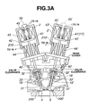
- Fig. 3A is a cross sectional view of electromagnetically operated intake and exhaust valves of the internal combustion engine shown in Fig. 1A for explaining a closure position of an engine valve.
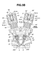
- Fig. 3B is a cross sectional view of the electromagnetically operated intake and exhaust valves of the engine shown in Fig. 1A for explaining a neutral position (initial position or half open position) of the engine valve.
- Fig. 3C is a cross sectional view of the electromagnetically operated intake and exhaust valves of the engine shown in Fig. 1A for explaining a full open position of the engine valve.
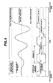
- Fig. 4 is a timing chart of a resonance initialization of the electromagnetically operated engine valve for explaining the resonance initialization applicable to the first preferred embodiment shown in Fig. 1A.
- Fig. 5 is a timing chart representing patterns of armature displacements when the intake valve and exhaust valve are initialized with a resonance at mutually different open-and-closure positions in the first embodiment shown in Fig. 1A.
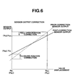
- Fig. 6 is a graph representing a pattern of a correction of a detected value of a position sensor of the electromagnetically operated engine valve position controlling apparatus in the first embodiment shown in Fig.' 1A according to the present invention.
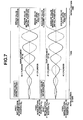
- Fig. 7 is a timing chart representing the pattern of the armature displacements (valve displacements) when the intake valve and exhaust valves for respective cylinders are initialized at mutually different open-and-closure positions applicable to a second preferred embodiment of the electromagnetically operated engine valve position controlling apparatus.
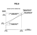
- Fig. 8 is a graph representing the pattern of the correction of the detected value of the position sensor in the second embodiment.
- Fig. 9 is a timing chart representing the patterns of the armature displaced position (valve displacement) when the initializations of both intake and exhaust valves are carried out at different open-and-closure positions from those before the initialization applicable to a third preferred embodiment of the electromagnetically operated engine valve position controlling apparatus according to the present invention.
- Fig. 10 is a characteristic graph representing the pattern of the correction of the detected value of the position sensor for the intake valve carried out in the third embodiment of the electromagnetically operated engine valve position controlling apparatus according to the present invention.
- Fig. 11 is a characteristic graph representing the pattern of the correction of the detected value of the position sensor for the exhaust valve carried out in the third embodiment of the electromagnetically operated engine valve position controlling apparatus according to the present invention.
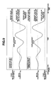
- Fig. 12 is a timing chart representing patterns of armature displacements of the intake and exhaust valves when the engine stops and when the intake and exhaust valves are initialized at the open-and-closure positions which are different from those when the engine stops applicable to a fourth preferred embodiment of the electromagnetically operated engine valve position controlling apparatus according to the present invention.
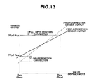
- Fig. 13 is a characteristic graph representing the pattern of the correction of the detected value of the position sensor for the intake valve described in the fourth preferred embodiment.
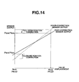
- Fig. 14 is a characteristic graph representing the pattern of the correction of the detected value of the position sensor for the exhaust valve described in the fourth preferred embodiment.
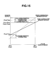
- Fig. 15 is a characteristic graph representing the pattern of the correction of the detected value of the position sensor for the intake valve carried out in a fifth preferred embodiment of the electromagnetically operated engine valve position controlling apparatus.
- Fig. 16 is a characteristic graph representing the pattern of the correction of the detected value of the position sensor for the exhaust valve carried out in the fifth preferred embodiment of the electromagnetically operated engine valve position controlling apparatus according to the present invention.
- Fig. 1A shows an internal combustion engine to which an apparatus for controlling a position of an electromagnetically operated engine valve in a first preferred embodiment according to the present invention is applicable.
- an internal combustion engine 1 is provided with an intake valve 3 and an exhaust valve 4.
- the electromagnetically operated engine valve is applied to each of intake valve 3 and exhaust valve 4.
- Intake valve 3 includes an electromagnetically variable drive unit 2' and exhaust valve 4 includes an electromagnetically variable drive unit 2.
- a fuel injection valve 6 is equipped within an intake port 5 and a combustion chamber 7 is equipped with a spark plug 8 and an ignition coil 9.
- a crank angle sensor 10 outputs a reference signal whenever an engine crankshaft revolves through a reference angle for each cylinder and outputs a unit angle signal whenever the engine crankshaft has revolved though a unit angle.
- An engine coolant temperature sensor 11 to detect an engine coolant temperature is attached onto engine 1.
- An airflow meter 13 to detect an intake air quantity is installed in an intake air passage 12 located within an upstream portion to intake port 5.
- An air-fuel ratio sensor 15 is installed within an exhaust passage 14 to detect an air-fuel ratio via a detection of an oxygen concentration in exhaust gas.
- a reference numeral 21 denotes an ignition switch to detect whether an ignition switch is turned on or off and a reference numeral 22 denotes a start switch to detect whether an engine start switch is turned on or off.
- a controller 16 receives detection signals from various sensors. Controller 16 outputs a fuel injection pulse signal to fuel injection valve 6 for its corresponding cylinder to perform the fuel injection control (viz., start timing and fuel injection quantity) on the basis of the detection signals from various sensors and outputs an ignition signal to each ignition coil 9 to perform an ignition timing control on the basis of the detection signals from the various sensors. Controller 16 further outputs valve drive signals to electromagnetically variable drive units 2 and 2' to control open-and-closure control for intake valve 3 and exhaust valve 4 on the basis of the detection signals of the sensors.
- Fig. 1B shows a rough configuration view of controller 16 and its peripheral circuit including the electromagnetically operated engine valve in the first embodiment.
- Fig. 2 shows a functional block diagram of an electromagnetic valve position control apparatus according to the present invention in the first preferred embodiment.
- controller 16 includes an engine control block 16A and electromagnetically oeprated engine valve control blocks 16B and 16C.
- Engine control block 16A includes a microcomputer having a CPU (Central Processing Unit) 160a, a RAM (Random Access Memory) 160b; a ROM (Read Only Memory) 160c; an Input Port 160d; an Output Port 160e; and common bus.
- CPU Central Processing Unit
- RAM Random Access Memory
- ROM Read Only Memory
- intake and exhaust valve control blocks 16B and 16C shown in Fig. 1B are described functionally, parts of each block 16B and 16C are constituted by the microcomputer described above. It is also noted that these blocks 16B and 16C are for a typical engine cylinder but the same blocks are applied to each of the engine cylinders.
- Exhaust (intake) valve control block 16B (16C) includes a movable element position sensor 55 (55')(hereinafter, referred simply to as a position sensor) which outputs a signal indicative of a position of an armature 42 (42') constituting a movable element of exhaust (intake) valve 4 (3) to a valve displacement compare/correcting section 56 (62) to correct a relationship between an output signal value of position sensor 55 (55') and a detected value of position of armature 42 (42') (actual position value of armature 42') as will be described later.
- the corrected position signal is supplied to a velocity target value generating section 57 (63).
- Velocity target value generating section 57 (63) generates a target value of a velocity of the valve body (valve stem 31 (31')) of exhaust (intake) valve 4 (3), i.e. , the valve displacement position of exhaust (intake) valve 4 (3).
- the target value of the velocity of exhaust (intake) valve 4 (3) is supplied to a current target value generating section 58 (64).
- Current target value generating section 58 (64) generates a target value of an electric current flowing through either a valve opening electromagnet 43 (43') or a valve closing electromagnet 44 (44') in response to a valve open command or a valve close command from engine controlling block 16A on the basis of the target value of the velocity of valve at velocity target value generating section 57 (63).
- a switching section 59 switches to connect current target value generating section 58 (64) to either a valve closing electromagnet current controlling section 60 (66) or a valve opening electromagnet current controlling section 61 (67), in response to the valve close command or the valve open command.
- Valve closing or opening electromagnet current controlling section 60 or 61 (66 or 67) is connected to either valve closing electromagnet 43 (43') or valve opening electromagnet 44 (44') in response to the active valve close command or the active valve open command.
- valve closing electromagnet current controlling section 60 and valve opening electromagnet current controlling section 61 are replaced with the same sections 66 and 67 in the case of intake valve 3 and a power supply section 70 includes a vehicular battery and a power supply booster.
- Figs. 3A, 3B, and 3C show cross sectional views of electromagnetically operated intake and exhaust valves 3 and 4 for explaining a closure position, a neutral position (half open position), and a full open position of the electromagnetically operated engine valve to which the electromagnetically operated engine valve position controlling apparatus in the first embodiment according to the present invention is applicable .
- exhaust (intake) valve 4 (3) is attached conventionally onto a cylinder head 18.
- the valve stem 31 (31') of exhaust (intake) valve 4 (3) is slidably inserted along a valve guide 19 (19').
- An upper seat 32 (32') is attached onto an upper completion of valve stem 31 (31') via a valve cotter.
- a valve closing spring 33 (33') (compressed by a predetermined compression distance from a free length) is interposed between upper seat 32 (32') and the lower seat provided at the cylinder head to bias exhaust (intake) valve 4 (3) in a valve closure direction.
- valve drive unit 2 (2') is coaxially disposed on the same axle as valve stem 31 (31') with a predetermined valve clearance, viz., with a predetermined space apart from an upper end of valve stem 31 (31').
- the valve drive unit 2 (2') includes: a housing 41 (41') made of a non-electromagnetic material; armature (armature plate) 42 (42') integrally attached onto movable axle 40 (40') slidably attached within housing 41 (41'); a valve closing spring 33 (33') to bias exhaust (intake) valve 4 (3) in the valve closure direction which is disposed between upper seat 32 (32') and the lower seat at cylinder head 18; valve closing electromagnet 43 (43') fixed within housing 41 (41') at a position facing toward an upper surface of armature 42 (42') so as to enable a magnetic attraction of armature 42 (42'); valve opening electromagnet 44 (44') fixed within housing 41 (41') at a position facing toward a lower surface of armature 42 (42') so as to enable a magnetic attraction of armature 42 (42'); and a valve opening spring 45 (45') which biases armature 42 (42') in the valve opening direction of exhaust (
- exhaust valve 4 is so structured as to be at the half open position (also called, the neutral position) due to only the spring force exerted by the pair of springs 45 and 33.
- valve closing electromagnet 43 when the power supply to valve closing electromagnet 43 is turned on to energize only valve closing electromagnet 43, armature 42 is magnetically attracted toward valve closing electromagnet 43 in the direction to which valve opening spring 45 is compressed.
- valve closing spring 33 when only valve opening electromagnet 44 is energized with exhaust valve 4 held at the half open position, armature 42 causes valve closing spring 33 to be compressed so as to be magnetically attracted toward valve opening electromagnet 44 to displace exhaust valve 4 at the full open position.
- position sensor 55 (55') to detect a position of armature 42 (42') is attached on an uppermost housing wall of valve drive unit 2 (2').
- the position sensor 55 (55') is constituted by, for example, an eddy current sensor or a Hall Effect device. While position sensor 55 (55') detects position of the armature 42 (42'), the power supply control between the valve closing electromagnet 43 (43') and valve opening electromagnet 44 (44') is carried out in such a manner that armature 42 (42') is driven with characteristics each having the target value of the velocity for a corresponding position of armature 42 (42').
- the armature 42 (42') is driven at a relatively high velocity from a time at which armature 42 (42') is separated from one electromagnet and is displaced toward the other electromagnet to secure the response characteristic.
- Fig. 3A shows the state of the electromagnetically operated engine valve in the closure position
- Fig. 3B shows the state thereof in the neutral position
- Fig. 3C shows the state thereof in the full open position.
- recesses 210 and 210' are provided for collecting wires of the electromagnets in respective housings 41 and 41' and reference numerals 200 and 200' denote valve seats.
- the initialization such that intake valve 3 or exhaust valve 4 is held from the half-open position to the full open position or the full closure position is carried out.
- the initialization is the alternating supply of power from valve opening electromagnet 44 (44') to valve closing electromagnet 43 (43') and the action of pair of springs 33 (33') and 45 (45') causes the resonance phenomenon to augment the amplitude of supplied currents to the electromagnets and, thereafter, intake (exhaust) valve 3(4) is held at the full open position or at the closure position (refer to Fig. 4).
- controller 16 performs the correction of the detected value of position sensor 55 (55'), namely, the valve displacement compare/correcting block 56 (62) performs a correction of a relationship between the output signal value (voltage) of position sensor 55 (55') for exhaust (intake) valve 4 (3) and the detected value of the armature displaced position (an actual value of the displaced position of armature 42 (42')) (hereinafter, simply called a correction of the detected value of position sensor 55(55')).
- the correction of the detected value of position sensor 55 for exhaust valve 4 is carried out on the basis of the output value of position sensor 55 which corresponds to the closure position of exhaust valve 4 upon a completion of initialization and that of position sensor 55' for the intake valve 3 which corresponds to the full open position of intake valve 3 upon the completion of initialization.
- the correction of the detected value of position sensor 55 for exhaust valve 4 may be carried out on the basis of the output value of position sensor 55 which corresponds to the full open position of exhaust valve 4 upon the completion of initialization and corresponds to the signal output value of the position sensor 55' which corresponds to the closure position of intake valve 3 upon the completion of initialization. Furthermore, the correction of the detected value of position sensor 55' is carried out on the basis of the output value of position sensor 55' which corresponds to the full open position of intake valve 3 upon the completion of initialization and that of position sensor 55 which corresponds to the full closure position of exhaust valve 4 upon the completion of initialization.
- the correction method for exhaust valve 4 is two combinations and that for intake valve 3 is two combinations.
- Fig. 5 shows patterns of the initializations for intake and exhaust valves 3 and 4 in the case of the first embodiment.
- intake valve 3 upon the completion of initialization is held at valve closure position H IC as denoted by a solid line of Fig. 5.
- Exhaust valve 4 upon the completion of initialization is held at the full open position H EO as denoted by the solid line. It is noted that, as denoted by a dot-and-dash line of Fig. 4, intake valve 3 may be held at the full open position upon the completion of initialization and exhaust valve 4 may be held at the full closure position.
- Fig. 6 shows patterns of the correction of the detected value of position sensor 55 (55') in the first embodiment.
- the correction of the detected value of position sensor 55 (55') for exhaust (intake) valve 4 (3) is carried out as a characteristic connecting the output signal value V IC of position sensor 55' which corresponds to the closure position H IC of intake valve 3 upon the completion of the initialization to the output signal value V EO of position sensor 55 which corresponds to the full open position H EO of exhaust valve 4 thereupon by a straight line. Consequently, both of a full open position correction and a closure position correction are carried out as denoted by arrows shown in Fig. 6 for the sensor output before the correction as denoted by a dot line and the valve displacement (armature). An intermediate opening position (between the full open position and the closure position) is accordingly corrected.
- the correction of the detected value of position sensor 55 (55') for exhaust (intake) valve 4 (3) may be carried out as the characteristic connecting the output signal value V EC of position sensor 55 which corresponds to the closure position of exhaust valve 4 upon the completion of the initialization to the output signal value V IO of position sensor 55' which corresponds to the full open position H IO of intake valve 3 thereupon by the straight line.
- Fig. 7 shows an example of the patterns of the initializations carried out in a second preferred embodiment of the electromagnetically operated engine valve position controlling apparatus according to the present invention.
- the other structure of the second embodiment is generally the same as that of the first embodiment.
- the open-and-closure position of intake valve 3 upon the completion of initialization is made different from that of exhaust valve 4 thereupon for each cylinder although the correction method becomes complicated in terms of control procedure.
- intake valve 3 is held at the full open position #1H IO and exhaust valve 4 is held at the closure position #1H EC .
- intake valve 3 is held at the closure position #2H IC and exhaust valve 4 is held at the full open position #2H EO .
- the correction of the detected value of the position sensor 55' for intake valve 3 is carried out in the same manner as described in the first embodiment with reference to Fig. 6 on the basis of the output signal value #1V IO of position sensor 55' which corresponds to the full open position #1H IO of intake valve 3 of the first cylinder #1 and the output signal value #2V IC of position sensor 55' which corresponds to the closure position #2H IC of intake valve 3 of the second cylinder #2 using a table of Fig. 8.
- the correction of the position sensor 55 for exhaust valve 4 is carried out in the same manner as described in the first embodiment with reference to Fig. 6 on the basis of the output signal value #1V EC of position sensor 55 which corresponds to the closure position #1H EC of exhaust valve 4 of the first cylinder #1 and the output value #2V EO of position sensor 55 which correspond to the full open position #2H EO of exhaust valve 4 of the second cylinder #2.
- These corrections apply equally well to any other cylinders of the internal combustion engine 1.
- Fig. 8 shows the correction pattern for position sensor 55' (55) in the second embodiment as described above.
- the corrections of the detected values of position sensors 55 (55') for the respective cylinders are carried out on the basis of the output values of position sensors 55 (55') for the same kinds of engine valves, viz., intake valves and exhaust valves 3 and 4 in the respective cylinders, an accuracy of the correction can be improved.
- the correction of the detected value of position sensor 55 (55') for each of exhaust and intake valves 4 and 3 is carried out on the basis of the output value of position sensor 55 (55') at the half open position (the neutral position) of the corresponding engine valve before the initialization (or called a prior-initialization) and the output value of position sensor 55 (55') at either the full open position thereof or the closure position thereof upon the completion of the initialization (or called a post-initialization).
- the other structure of the electromagnetically operated engine valve position controlling apparatus in the third embodiment is generally the same as described in the first embodiment.
- Fig. 9 shows patterns of initialization for intake valve 3 and exhaust valve 4 applicable to the third embodiment in which intake valve 3 is held at the closure position H IC upon the completion of initialization and exhaust valve 4 is held at the full open position H EO thereupon.
- the correction of the detected value of position sensor 55' is carried out on the basis of the output value V IM of position sensor 55' at the neutral position (or called, the initial position) H IM before the initialization and the output value V IC thereof at the closure position H IC thereof upon the completion of initialization, as appreciated from Fig. 10.
- the correction of the detected value of position sensor 55 for exhaust valve 4 is carried out on the basis of the output value V EM of position sensor 55 at the neutral position of exhaust valve 4 before the initialization and the output value V EO of position sensor 55 at the full open position H EO of exhaust valve 4 upon the completion of initialization, as shown in Fig. 11.
- a simple connection using the output value of position sensor 55 at the normal initialization setting can be made.
- the simple correction is carried out using the output value of position sensor 55 at the normal initialization setting in the same way as described in the first embodiment.
- the accuracy of correction can be improved using two output values of the same position sensors 55 and 55' in the same valve.
- the accuracy of correction may slightly be reduced.
- the engine valve is temporarily held at the open-and-closure position which is different from that upon the completion of initialization and the output value of position sensor 55 (55') is stored in a memory such as the RAM. Then, the correction of the detected value of position sensor 55 (55') is carried out on the basis of the output value of position sensor 55 (55') upon the completion of initialization carried out before the engine start and the output value thereof stored during the previous engine stop.
- Fig. 12 shows the pattern of initializations for the intake and exhaust valves 3 and 4 which have temporarily been held during the engine stop applicable to the fourth embodiment of the electromagnetically operated engine valve position controlling apparatus.
- the other structure of the electromagnetically operated engine valve position controlling apparatus in the fourth embodiment is generally the same as described in the first embodiment.
- intake valve 3 is temporarily held at the full open position H IOS during the engine stop.
- intake valve 3 is held at the closure position H ICS and exhaust valve 4 is held at the full open position H EOS .
- the correction of the detected value of position sensor 55' is carried out on the basis of the output value V IOE of the temporarily held full open position H IOE during the engine stop and the output value V ECE of the closure position H ECE upon the completion of initialization as shown in Fig. 13.
- the correction of the detected value of position sensor 55 is carried out on the basis of the output value V ECE of position sensor 55 at the temporarily held closure position H ECE of exhaust valve 4 during the engine stop and the output value V EOS of the full open position upon the completion of the initialization as shown in Fig. 14.
- the correction of the detected value of position sensor 55 (55') with a high accuracy can be achieved using the output values of the same position sensor 55 (55') which correspond to that when the same engine valve is displaced at the full open position and which corresponds to that when the same engine valve is displaced at the closure position.
- a temperature difference generally occurs during the engine stop and during the start. If the temperature difference occurs, the output value of position sensor 55 (55') is varied.
- the correction of the detected value of position sensor 55 (55') is carried out on the basis of the temperature difference between the engine stop and the engine start as well as those described in the fourth embodiment.
- the other structure of the electromagnetically operated engine valve is generally the same as described in the first embodiment.
- intake valve 3 is temporarily held at the full open position H IOE during the engine stop and exhaust valve 4 is held at the closure position H ECS during the engine stop.
- intake valve 3 is held at the closure position H ICS and exhaust valve 4 is held at the full open position H EOS .
- the output value V IOE of position sensor 55' corresponding to the full open position H IOE of intake valve 3 during the engine stop is corrected with a correction ⁇ V IOS corresponding to the temperature difference ⁇ Tw.
- the correction of the output value V ECE corresponding to the closure position H ECE of exhaust valve 4 during the engine stop is corrected with a correction coefficient ⁇ V ECS which accords with the temperature difference ⁇ Tw so that the output value V ECE of position sensor 55 is corrected on the basis of the corrected output value of (V ECS - ⁇ V ECS ) and the full open position H EOS of exhaust valve 4 upon the completion of initialization during the engine start as shown in Fig. 16.
- the relationship between the output signal value of position sensor 55 (55') and the detected value of armature position 42 (42') is corrected after the output value correction corresponding to the temperature difference is made.
- the highly accurate correction of the detected value of the armature can be achieved.
- a lubricating oil temperature sensor 17 may be disposed in housing 41' of intake valve drive unit 2' so that the temperature difference based correction described in the fifth embodiment may be carried out using the lubricating oil temperature placed in the vicinity to the valve body sliding portion of the intake and exhaust valves detected with lubricating oil temperature sensor 17. A highly accurate temperature difference based correction can be made.
Landscapes
- Engineering & Computer Science (AREA)
- Mechanical Engineering (AREA)
- General Engineering & Computer Science (AREA)
- Chemical & Material Sciences (AREA)
- Combustion & Propulsion (AREA)
- Analytical Chemistry (AREA)
- Valve Device For Special Equipments (AREA)
- Output Control And Ontrol Of Special Type Engine (AREA)
- Combined Controls Of Internal Combustion Engines (AREA)
- Magnetically Actuated Valves (AREA)
Applications Claiming Priority (2)
| Application Number | Priority Date | Filing Date | Title |
|---|---|---|---|
| JP2000013223A JP3873559B2 (ja) | 2000-01-21 | 2000-01-21 | エンジンの電磁動弁制御装置 |
| JP2000013223 | 2000-01-21 |
Publications (3)
| Publication Number | Publication Date |
|---|---|
| EP1136659A2 true EP1136659A2 (fr) | 2001-09-26 |
| EP1136659A3 EP1136659A3 (fr) | 2002-06-12 |
| EP1136659B1 EP1136659B1 (fr) | 2006-04-19 |
Family
ID=18540840
Family Applications (1)
| Application Number | Title | Priority Date | Filing Date |
|---|---|---|---|
| EP01101081A Expired - Lifetime EP1136659B1 (fr) | 2000-01-21 | 2001-01-18 | Dispositif et procédé de controle de la position d'une soupape de moteur à commande électromagnétique |
Country Status (4)
| Country | Link |
|---|---|
| US (1) | US6343577B2 (fr) |
| EP (1) | EP1136659B1 (fr) |
| JP (1) | JP3873559B2 (fr) |
| DE (1) | DE60118826T2 (fr) |
Cited By (8)
| Publication number | Priority date | Publication date | Assignee | Title |
|---|---|---|---|---|
| EP1264969A3 (fr) * | 2001-06-08 | 2003-07-30 | Toyota Jidosha Kabushiki Kaisha | Dispositif et méthode de détection de modification de la position d'équilibre d'une soupape dans le cas d'un système d'actionnement électromagnétique de soupape, dispositif et méthode de commande de soupape |
| DE10302132B4 (de) * | 2002-01-21 | 2006-01-05 | Toyota Jidosha K.K., Toyota | Elektromagnetische Ventilsteuerung für eine Brennkraftmaschine |
| DE102005004731A1 (de) * | 2005-02-02 | 2006-08-10 | Daimlerchrysler Ag | Vorrichtung mit einer Einheit zum Betätigen einer Brennkraftmaschine |
| WO2007066706A1 (fr) * | 2005-12-05 | 2007-06-14 | Toyota Jidosha Kabushiki Kaisha | Appareil de commande pour moteur a combustion interne |
| EP1455058A3 (fr) * | 2003-03-05 | 2008-10-15 | Toyota Jidosha Kabushiki Kaisha | Dispositif de commande électromagnétique de soupape et méthode |
| EP1577526A3 (fr) * | 2004-03-19 | 2010-07-07 | Ford Global Technologies, LLC | Une méthode pour mettre en mouvement les valves électromécaniques d'un moteur à combustion interne |
| US7865290B2 (en) * | 2007-10-09 | 2011-01-04 | Ford Global Technologies, Llc | Valve control synchronization and error detection in an electronic valve actuation engine system |
| WO2014023949A1 (fr) * | 2012-08-06 | 2014-02-13 | Camcon Auto Limited | Système de commande de soupape destiné à des moteurs à combustion interne et procédé de fonctionnement de celui-ci |
Families Citing this family (7)
| Publication number | Priority date | Publication date | Assignee | Title |
|---|---|---|---|---|
| JP3689614B2 (ja) * | 2000-03-21 | 2005-08-31 | 株式会社日立製作所 | 位置測定装置の磁石固定方法 |
| JP4852809B2 (ja) * | 2001-09-04 | 2012-01-11 | トヨタ自動車株式会社 | 内燃機関の電磁吸気弁開弁誤差対処運転方法 |
| US6805079B1 (en) * | 2001-11-02 | 2004-10-19 | Diana D. Brehob | Method to control electromechanical valves |
| US6571757B1 (en) | 2002-04-22 | 2003-06-03 | Borgwarner Inc. | Variable force solenoid with spool position feedback to control the position of a center mounted spool valve to control the phase angle of cam mounted phaser |
| EP1700014B1 (fr) | 2003-12-18 | 2007-05-23 | Toyota Jidosha Kabushiki Kaisha | Mecanisme a soupape variable |
| EP2274521B1 (fr) * | 2008-04-22 | 2020-06-17 | Borgwarner Inc. | Procédé pour commander un actionneur |
| US9428164B2 (en) | 2013-02-28 | 2016-08-30 | Bendix Commercial Vehicle Systems Llc | Valve assembly |
Citations (1)
| Publication number | Priority date | Publication date | Assignee | Title |
|---|---|---|---|---|
| JP2000013223A (ja) | 1998-06-23 | 2000-01-14 | Toyo Commun Equip Co Ltd | 周波数シンセサイザ |
Family Cites Families (10)
| Publication number | Priority date | Publication date | Assignee | Title |
|---|---|---|---|---|
| DE3307070C2 (de) * | 1983-03-01 | 1985-11-28 | FEV Forschungsgesellschaft für Energietechnik und Verbrennungsmotoren mbH, 5100 Aachen | Stelleinrichtung für ein zwischen zwei Endstellungen verstellbares Schaltelement |
| JP2639587B2 (ja) * | 1989-03-30 | 1997-08-13 | 株式会社いすゞセラミックス研究所 | バルブのステッピング駆動装置 |
| US5596956A (en) * | 1994-12-16 | 1997-01-28 | Honda Giken Kogyo Kabushiki Kaisha | Electromagnetically driven valve control system for internal combustion engines |
| JP3683300B2 (ja) * | 1995-01-27 | 2005-08-17 | 本田技研工業株式会社 | 内燃機関の制御装置 |
| JP3881094B2 (ja) | 1997-09-01 | 2007-02-14 | 株式会社日本自動車部品総合研究所 | 電磁式弁駆動装置 |
| DE19736137C1 (de) * | 1997-08-20 | 1998-10-01 | Daimler Benz Ag | Verfahren zum Starten eines Verbrennungsmotors |
| DE19739840C2 (de) * | 1997-09-11 | 2002-11-28 | Daimler Chrysler Ag | Verfahren zur Steuerung einer elektromagnetisch betätigbaren Stellvorrichtung, insbesondere eines Ventils für Brennkraftmaschinen |
| JPH11148328A (ja) * | 1997-11-12 | 1999-06-02 | Fuji Heavy Ind Ltd | 電磁駆動バルブの開閉時期検出装置 |
| WO2000009972A1 (fr) * | 1998-08-12 | 2000-02-24 | Siemens Aktiengesellschaft | Procede pour determiner une position en fonction d'un signal de mesure emis par un capteur de position |
| US6158403A (en) * | 1999-03-30 | 2000-12-12 | Aura Systems, Inc. | Servo control system for an electromagnetic valve actuator used in an internal combustion engine |
-
2000
- 2000-01-21 JP JP2000013223A patent/JP3873559B2/ja not_active Expired - Fee Related
-
2001
- 2001-01-18 EP EP01101081A patent/EP1136659B1/fr not_active Expired - Lifetime
- 2001-01-18 DE DE60118826T patent/DE60118826T2/de not_active Expired - Lifetime
- 2001-01-19 US US09/764,071 patent/US6343577B2/en not_active Expired - Lifetime
Patent Citations (1)
| Publication number | Priority date | Publication date | Assignee | Title |
|---|---|---|---|---|
| JP2000013223A (ja) | 1998-06-23 | 2000-01-14 | Toyo Commun Equip Co Ltd | 周波数シンセサイザ |
Cited By (11)
| Publication number | Priority date | Publication date | Assignee | Title |
|---|---|---|---|---|
| EP1264969A3 (fr) * | 2001-06-08 | 2003-07-30 | Toyota Jidosha Kabushiki Kaisha | Dispositif et méthode de détection de modification de la position d'équilibre d'une soupape dans le cas d'un système d'actionnement électromagnétique de soupape, dispositif et méthode de commande de soupape |
| DE10302132B4 (de) * | 2002-01-21 | 2006-01-05 | Toyota Jidosha K.K., Toyota | Elektromagnetische Ventilsteuerung für eine Brennkraftmaschine |
| EP1455058A3 (fr) * | 2003-03-05 | 2008-10-15 | Toyota Jidosha Kabushiki Kaisha | Dispositif de commande électromagnétique de soupape et méthode |
| EP1577526A3 (fr) * | 2004-03-19 | 2010-07-07 | Ford Global Technologies, LLC | Une méthode pour mettre en mouvement les valves électromécaniques d'un moteur à combustion interne |
| DE102005004731A1 (de) * | 2005-02-02 | 2006-08-10 | Daimlerchrysler Ag | Vorrichtung mit einer Einheit zum Betätigen einer Brennkraftmaschine |
| WO2007066706A1 (fr) * | 2005-12-05 | 2007-06-14 | Toyota Jidosha Kabushiki Kaisha | Appareil de commande pour moteur a combustion interne |
| US7813864B2 (en) | 2005-12-05 | 2010-10-12 | Toyota Jidosha Kabushiki Kaisha | Control apparatus for internal combustion engine |
| CN101321932B (zh) * | 2005-12-05 | 2010-11-03 | 丰田自动车株式会社 | 用于内燃发动机的控制设备 |
| US7865290B2 (en) * | 2007-10-09 | 2011-01-04 | Ford Global Technologies, Llc | Valve control synchronization and error detection in an electronic valve actuation engine system |
| WO2014023949A1 (fr) * | 2012-08-06 | 2014-02-13 | Camcon Auto Limited | Système de commande de soupape destiné à des moteurs à combustion interne et procédé de fonctionnement de celui-ci |
| US9523292B2 (en) | 2012-08-06 | 2016-12-20 | Camcon Auto Limited | Valve control system for internal combustion engines and method of operation thereof |
Also Published As
| Publication number | Publication date |
|---|---|
| JP3873559B2 (ja) | 2007-01-24 |
| DE60118826D1 (de) | 2006-05-24 |
| US6343577B2 (en) | 2002-02-05 |
| DE60118826T2 (de) | 2006-08-31 |
| US20010027759A1 (en) | 2001-10-11 |
| EP1136659B1 (fr) | 2006-04-19 |
| JP2001207876A (ja) | 2001-08-03 |
| EP1136659A3 (fr) | 2002-06-12 |
Similar Documents
| Publication | Publication Date | Title |
|---|---|---|
| US6343577B2 (en) | Apparatus and method for controlling position of electromagnetically operated engine valve of internal combustion engine | |
| EP0717172B1 (fr) | Dispositif de commande de soupape électromagnétique pour moteurs à combustion interne | |
| EP1076163B1 (fr) | Méthode et dispositif pour le contrôle de soupapes électromagnétiques en fonction des données initiales avant le démarrage du moteur | |
| US6588385B2 (en) | Engine valve drive control apparatus and method | |
| EP1151186B1 (fr) | Appareil pour controler la position d'une soupape de moteur a commande electromagnetique | |
| US6477993B1 (en) | Control device for solenoid driving valve | |
| EP0964141A2 (fr) | Dispositif de commande de recirculation de gaz d'échappement pour moteur à combustion interne | |
| US6549390B1 (en) | Actuator controller | |
| JP2001505637A (ja) | 燃料噴射弁の移動を検知する装置及び方法 | |
| US6634327B2 (en) | Apparatus and method for detecting change of neutral position of valve of electromagnetic valve actuation system, and apparatus and method for controlling the valve | |
| JP2001520494A (ja) | 電気機械的調整装置の制御方法 | |
| CN121548688A (zh) | 燃料喷射控制装置及燃料喷射控制方法 | |
| JP4089614B2 (ja) | 電磁駆動弁の可変フィードバックゲイン通電制御方法 | |
| JP4080551B2 (ja) | 内燃機関の制御装置 | |
| US6973900B2 (en) | Valve drive system and method | |
| JP3541685B2 (ja) | 電磁駆動弁の電流制御装置 | |
| JP3424426B2 (ja) | 内燃機関の電磁弁駆動装置 | |
| JP2978961B2 (ja) | 内燃機関の電磁駆動弁制御装置 | |
| JP4045858B2 (ja) | 内燃機関用電磁駆動弁の起動制御装置 | |
| JP3629963B2 (ja) | 電磁駆動弁の電流制御装置 | |
| EP1371820A2 (fr) | Dispositif de commande pour soupapes à actionnement électromagnétique | |
| JP2002242708A (ja) | 内燃機関用直動弁の駆動装置 | |
| WO2026053508A1 (fr) | Dispositif de commande pour dispositif d'injection de carburant et procédé de commande pour dispositif d'injection de carburant | |
| JP2001050065A (ja) | エンジンの電磁動弁制御装置 | |
| JP2007056782A (ja) | 内燃機関の燃料噴射量制御装置、ならびに多気筒型内燃機関の制御装置 |
Legal Events
| Date | Code | Title | Description |
|---|---|---|---|
| PUAI | Public reference made under article 153(3) epc to a published international application that has entered the european phase |
Free format text: ORIGINAL CODE: 0009012 |
|
| 17P | Request for examination filed |
Effective date: 20010118 |
|
| AK | Designated contracting states |
Kind code of ref document: A2 Designated state(s): AT BE CH CY DE DK ES FI FR GB GR IE IT LI LU MC NL PT SE TR |
|
| AX | Request for extension of the european patent |
Free format text: AL;LT;LV;MK;RO;SI |
|
| PUAL | Search report despatched |
Free format text: ORIGINAL CODE: 0009013 |
|
| AK | Designated contracting states |
Kind code of ref document: A3 Designated state(s): AT BE CH CY DE DK ES FI FR GB GR IE IT LI LU MC NL PT SE TR |
|
| AX | Request for extension of the european patent |
Free format text: AL;LT;LV;MK;RO;SI |
|
| RIC1 | Information provided on ipc code assigned before grant |
Free format text: 7F 01L 9/04 A, 7F 01L 1/46 B, 7F 02D 13/02 B, 7F 02D 45/00 B |
|
| AKX | Designation fees paid |
Designated state(s): DE FR GB |
|
| 17Q | First examination report despatched |
Effective date: 20031105 |
|
| GRAP | Despatch of communication of intention to grant a patent |
Free format text: ORIGINAL CODE: EPIDOSNIGR1 |
|
| GRAS | Grant fee paid |
Free format text: ORIGINAL CODE: EPIDOSNIGR3 |
|
| GRAA | (expected) grant |
Free format text: ORIGINAL CODE: 0009210 |
|
| AK | Designated contracting states |
Kind code of ref document: B1 Designated state(s): DE FR GB |
|
| REG | Reference to a national code |
Ref country code: GB Ref legal event code: FG4D |
|
| REF | Corresponds to: |
Ref document number: 60118826 Country of ref document: DE Date of ref document: 20060524 Kind code of ref document: P |
|
| ET | Fr: translation filed | ||
| PLBE | No opposition filed within time limit |
Free format text: ORIGINAL CODE: 0009261 |
|
| STAA | Information on the status of an ep patent application or granted ep patent |
Free format text: STATUS: NO OPPOSITION FILED WITHIN TIME LIMIT |
|
| 26N | No opposition filed |
Effective date: 20070122 |
|
| PGFP | Annual fee paid to national office [announced via postgrant information from national office to epo] |
Ref country code: DE Payment date: 20140115 Year of fee payment: 14 |
|
| PGFP | Annual fee paid to national office [announced via postgrant information from national office to epo] |
Ref country code: FR Payment date: 20140108 Year of fee payment: 14 |
|
| PGFP | Annual fee paid to national office [announced via postgrant information from national office to epo] |
Ref country code: GB Payment date: 20140115 Year of fee payment: 14 |
|
| REG | Reference to a national code |
Ref country code: DE Ref legal event code: R119 Ref document number: 60118826 Country of ref document: DE |
|
| GBPC | Gb: european patent ceased through non-payment of renewal fee |
Effective date: 20150118 |
|
| PG25 | Lapsed in a contracting state [announced via postgrant information from national office to epo] |
Ref country code: DE Free format text: LAPSE BECAUSE OF NON-PAYMENT OF DUE FEES Effective date: 20150801 Ref country code: GB Free format text: LAPSE BECAUSE OF NON-PAYMENT OF DUE FEES Effective date: 20150118 |
|
| REG | Reference to a national code |
Ref country code: FR Ref legal event code: ST Effective date: 20150930 |
|
| PG25 | Lapsed in a contracting state [announced via postgrant information from national office to epo] |
Ref country code: FR Free format text: LAPSE BECAUSE OF NON-PAYMENT OF DUE FEES Effective date: 20150202 |