EP1136680B1 - Méthode pour générer un signal de sortie d'une pédale d'accélérateur - Google Patents
Méthode pour générer un signal de sortie d'une pédale d'accélérateur Download PDFInfo
- Publication number
- EP1136680B1 EP1136680B1 EP01105216A EP01105216A EP1136680B1 EP 1136680 B1 EP1136680 B1 EP 1136680B1 EP 01105216 A EP01105216 A EP 01105216A EP 01105216 A EP01105216 A EP 01105216A EP 1136680 B1 EP1136680 B1 EP 1136680B1
- Authority
- EP
- European Patent Office
- Prior art keywords
- pedal
- output signal
- released
- pedal position
- accelerator
- Prior art date
- Legal status (The legal status is an assumption and is not a legal conclusion. Google has not performed a legal analysis and makes no representation as to the accuracy of the status listed.)
- Expired - Lifetime
Links
- 238000000034 method Methods 0.000 title claims description 24
- 230000000994 depressogenic effect Effects 0.000 claims description 28
- 230000001133 acceleration Effects 0.000 claims description 23
- 238000006073 displacement reaction Methods 0.000 claims description 9
- 238000002485 combustion reaction Methods 0.000 claims description 3
- 230000003247 decreasing effect Effects 0.000 description 5
- 230000001427 coherent effect Effects 0.000 description 3
- 230000007423 decrease Effects 0.000 description 2
- 230000000881 depressing effect Effects 0.000 description 2
- 230000004044 response Effects 0.000 description 2
- 230000006399 behavior Effects 0.000 description 1
- 238000011217 control strategy Methods 0.000 description 1
- 230000000694 effects Effects 0.000 description 1
- 230000007704 transition Effects 0.000 description 1
Images


Classifications
-
- F—MECHANICAL ENGINEERING; LIGHTING; HEATING; WEAPONS; BLASTING
- F02—COMBUSTION ENGINES; HOT-GAS OR COMBUSTION-PRODUCT ENGINE PLANTS
- F02D—CONTROLLING COMBUSTION ENGINES
- F02D11/00—Arrangements for, or adaptations to, non-automatic engine control initiation means, e.g. operator initiated
- F02D11/06—Arrangements for, or adaptations to, non-automatic engine control initiation means, e.g. operator initiated characterised by non-mechanical control linkages, e.g. fluid control linkages or by control linkages with power drive or assistance
- F02D11/10—Arrangements for, or adaptations to, non-automatic engine control initiation means, e.g. operator initiated characterised by non-mechanical control linkages, e.g. fluid control linkages or by control linkages with power drive or assistance of the electric type
- F02D11/105—Arrangements for, or adaptations to, non-automatic engine control initiation means, e.g. operator initiated characterised by non-mechanical control linkages, e.g. fluid control linkages or by control linkages with power drive or assistance of the electric type characterised by the function converting demand to actuation, e.g. a map indicating relations between an accelerator pedal position and throttle valve opening or target engine torque
Definitions
- the present invention generally relates to a method for generating a pedal output signal of an accelerator pedal.
- ETC electronic throttle control
- Such Engines equipped with ETC are for example known from DE 44 03 604 A1, EP 0 962 350 A2 and US 4,881,428. They describe specific control strategies of the throttle valve position based on electronically determined pedal position information.
- JP 63 134829 describes a throttle valve control device, that aims at removing the fluctuation component of an accelerator operation quantity. This is done by adding hysteresis characteristics to the accelerator operation quantity to be detected by an acceleration quantity detecting means, and transmitting the accelerator operation quantity with the hysteresis characteristics to the ETC.
- the object of the present invention is to provide a method for generating a pedal output signal for ETC, which permits to reduce engine speed flares and more generally to improve a vehicle's driveability. This object is achieved by a method as claimed in claim 1.
- a method in accordance with the invention generally concerns the generation of a pedal output signal of an accelerator pedal for electronic load control of an internal combustion engine.
- the pedal output signal depends on the position of the accelerator pedal. Therefore, a variation of the pedal output signal may be produced by a displacement of said accelerator pedal. It shall be appreciated that, under given conditions, a given absolute variation in said pedal output signal is generated by a different accelerator pedal displacement depending on whether the accelerator pedal is depressed or released. This means that, under given conditions, a different pedal output signal is generated for a same pedal position depending on whether the accelerator pedal has been depressed or released.
- the pedal output signal is no longer generated so as to simulate a conventional accelerator pedal, i.e. mechanical accelerator pedal, producing a unique response of the engine to a given pedal displacement respectively a given pedal position, irrespective of acceleration or deceleration.
- the method of the invention permits to generate, in definable conditions, a different pedal output signal for a same pedal position. Therefore, the response of the engine to a pedal displacement can be adapted in function of preferred driving behaviors, thereby improving the driveability of the vehicle.
- a given absolute variation in said pedal output signal is produced by a shorter accelerator pedal displacement when said accelerator pedal is released than when it is depressed.
- a pedal output signal indicating an entirely released pedal i.e. an idle output signal, may be generated before the accelerator pedal has been entirely released.
- a first advantage of this method is that the engine speed will earlier reach the idle engine speed, thereby reducing engine speed flares during gearshifts.
- an idle output signal can be generated to prevent engine speed flares.
- An initial pedal movement is to depress the accelerator pedal from the entirely released pedal position.
- the pedal output signal may be generated according to an acceleration function with the actual pedal position as an argument. Now, if the pedal output signal is generated according to the acceleration function, i.e. the pedal is being depressed, and if the accelerator pedal is suddenly released, then the pedal output signal is generated according to a deceleration function.
- the deceleration function is steeper than the acceleration function, thereby ensuring a rapid decrease of the pedal output signal to the idle output signal.
- generating the pedal output signal according to the deceleration function implies an offset in the accelerator pedal.
- the deceleration function already generates an idle output signal for an offset pedal position different from the entirely released pedal position.
- the deceleration function may be used to generate the pedal output signal when the pedal has been released and is subsequently depressed. Indeed, using the acceleration function each time that the pedal is depressed and using the deceleration function each time that the accelerator pedal is released would produce discontinuities in the pedal output signal. In case that the pedal has been released and is subsequently depressed, the pedal output signal is therefore preferably generated according to the deceleration function or to a translation thereof, i.e. an analogous function which is parallel shifted, until it reaches the pedal output signal that would be generated according to the acceleration function. Then the pedal output signal will be generated according to the acceleration function.
- the deceleration function is translated so as to obtain a coherent and continuous pedal output signal. If the accelerator pedal has been released from the offset pedal position to a given pedal position and if it is depressed again, then the pedal output signal is generated according to the deceleration function shifted or translated by a value corresponding to the difference between the offset pedal position and the given pedal position. Hence, this shifted deceleration function generates an idle output signal for said given pedal position and the pedal output signal varies as with the deceleration function when the accelerator pedal is depressed.
- the method of the invention is implemented in order to generate a pedal output signal of an accelerator pedal in such a way that engine speed flares may be reduced or avoided during gearshifts. Therefore, in this preferred embodiment, under given conditions, a given absolute variation in the pedal output signal is produced by a shorter accelerator pedal displacement when the accelerator pedal is released than when it is depressed.
- absolute variation here means the absolute value of the variation, i.e. the value of the variation independently of its sign. It follows that a pedal output signal indicating an entirely released pedal, i.e. an idle output signal, may be generated before the accelerator pedal has been entirely released.
- the pedal output signal is preferably generated according to an acceleration function (face) or to a deceleration (f dec ), depending on the situation.
- An example for such acceleration and deceleration functions is shown in Fig. 1, where each of the functions is represented by a straight line.Numerical examples will be used for a better understanding of this preferred embodiment of the method of the invention.
- the pedal output signal (POS) is also assumed to range from 0 to 100%.
- a pedal output signal of 0% corresponds to an idle output signal.
- the accelerator pedal is depressed until the pedal position reaches e.g. 50%, and that it is subsequently released from that position, which shall be called switch position. Then, in accordance with the present method, the pedal output signal shall be given by the deceleration function. This means that the pedal output signal was given by f acc and that consequently to the release of the pedal, the pedal output signal is then given by f dec . More generally, this condition shall be respected every time the pedal is released while the pedal output signal is given by f acc .
- the deceleration function is steeper than the acceleration function.
- a pedal output signal of 0% i.e. idle output signal
- f dec 0% when the pedal position reaches an offset pedal position equal to PO, which shall be called offset pedal position.
- the slope of the deceleration function is a constant. It is preferably about 10% steeper than the slope of the acceleration function. However, in this embodiment, the slope has been set to 1.4 (i.e. 40% steeper) in order to exaggerate the effect of the method.
- the pedal offset depends on the switch position and is needed to obtain the equation of the deceleration function. Hence the pedal offset is calculated as soon as a release of the pedal is detected and a transition from face to f dec should be performed.
- the pedal output signal is generated according to the deceleration function.
- the pedal output signal is advantageously given by f dec as long as the pedal position is between the switch position and the offset pedal position. This ensures a coherent control of the pedal and the continuity of the pedal output signal. Indeed, if f acc was only used for depressed pedals and f dec for released pedals, there would be evident discontinuities in the values of the pedal output signal.
- the translation may be carried out by modifying the variable PP in the deceleration function f dec by a value corresponding to the pedal displacement between the offset pedal position and the current pedal position. For example, if the pedal is decreased to 7.5%, then POS shall be given by f dec (PP+(14.3-7.5)). In the present embodiment, the same result can be achieved by giving PO the value of the current pedal position.
- This translated f dec is indicated by reference sign D' in Fig.1. It allows the generation of a coherent pedal output signal since the pedal output signal thus varies as with the initial deceleration function.
- f dec (PP+(14.3-7.5)) reaches facc(PP) then the pedal output signal is again given by f acc, as previously explained.
- a convenient way to implement the present method is to adapt it for an on-board computer.
- the preferred flowchart for programming the method is shown in Fig.2.
- the pedal position is compared to the old pedal position in order to detect acceleration or deceleration.
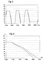
- Fig.3 and Fig.4 graphs representing the pedal position (continuous lines) and the resulting pedal output signal (dashed lines) are shown.
- the vertical axis represents the percentage of pedal position, resp. of pedal output signal.
- the horizontal axis indicates the time in ms, the origin of time being arbitrary.
- each peak corresponds to a gearshift.
- POS f acc (PP). Therefore in the increasing part of the peak the pedal output signal equals the pedal position.
- the deceleration function is used.
- the decreasing part of the second peak is shown in Fig.4.
- the present method permits, in this example, to reach the idle output signal (0%) 32 ms before the accelerator pedal is entirely released. It follows that engine speed flares can be reduced during gearshifts since an idle output signal is generated before the pedal has been entirely released.
- the third peak is characteristic of a "driver mistake" which can be corrected with the present method.
- the driver did not entirely release the accelerator pedal.
Landscapes
- Engineering & Computer Science (AREA)
- Chemical & Material Sciences (AREA)
- Combustion & Propulsion (AREA)
- Mechanical Engineering (AREA)
- General Engineering & Computer Science (AREA)
- Control Of Throttle Valves Provided In The Intake System Or In The Exhaust System (AREA)
Claims (5)
- Procédé de génération d'un signal de sortie de pédale indicatif de la position d'une pédale d'accélérateur à utiliser pour la commande électronique de charge d'un moteur à combustion interne, dans lequel dans des conditions données, une variation absolue donnée dudit signal de sortie de pédale est produite par un déplacement différent de la pédale d'accélérateur selon que l'on enfonce la pédale d'accélérateur ou qu'on la relâche, dans lequel ledit signal de sortie de pédale peut être généré selon une fonction d'accélération et, si ledit signal de sortie de pédale est généré selon ladite fonction d'accélération et indique une position de pédale enfoncée, alors si ladite pédale d'accélérateur est relâchée, ledit signal de sortie de pédale est généré selon une fonction de décélération, caractérisé en ce que ladite fonction de décélération génère un signal de sortie de pédale indiquant une position de pédale entièrement relâchée lorsque la pédale est relâchée à une position de pédale décalée différente de la position de pédale entièrement relâchée
- Procédé selon la revendication 1, caractérisé en ce que si ladite pédale d'accélérateur est encore relâchée de ladite position de pédale décalée, alors ladite fonction de décélération est translatée de manière à générer une sortie de signal de ralenti pour la position de pédale réelle
- Procédé selon la revendication 2, caractérisé en ce que si ladite pédale d'accélérateur a été relâchée, alors si ladite pédale d'accélérateur est enfoncée, ledit signal de sortie de pédale est généré selon ladite fonction de décélération ou une translation de celle-ci ;
et en ce que, si ledit signal de sortie de pédale généré selon ladite fonction de décélération ou ladite fonction de décélération translatée atteint le signal de sortie de pédale d'accélération qui serait généré selon ladite fonction d'accélération, alors ledit signal de sortie de pédale est généré selon ladite fonction d'accélération - Procédé selon la revendication 3, caractérisé en ce que si ladite pédale d'accélérateur a été relâchée de la position de pédale décalée à une position de pédale donnée et si ladite pédale d'accélérateur est ensuite enfoncée, alors le signal de sortie de pédale est généré selon ladite fonction de décélération translatée d'une valeur correspondant à la différence entre ladite position de pédale décalée et ladite position de pédale donnée
- Procédé selon l'une quelconque des revendications 1 à 4, caractérisé en ce que ladite fonction d'accélération a la forme suivante :facc(position pédale) = A1*position pédale, avec facc (position pédale entièrement relâchée) = signal de sortie de ralenti ; et la fonction de décélération a la forme suivante :fdec (position pédale) = A2*(position pédale - décalage pédale), avec A2>A1 etfdec (position pédale décalée) = signal de sortie de ralenti.
Applications Claiming Priority (2)
| Application Number | Priority Date | Filing Date | Title |
|---|---|---|---|
| LU90555A LU90555B1 (en) | 2000-03-23 | 2000-03-23 | Method for generating a pedal output signal of an accelerator pedal |
| LU90555 | 2000-03-23 |
Publications (2)
| Publication Number | Publication Date |
|---|---|
| EP1136680A1 EP1136680A1 (fr) | 2001-09-26 |
| EP1136680B1 true EP1136680B1 (fr) | 2006-08-23 |
Family
ID=19731882
Family Applications (1)
| Application Number | Title | Priority Date | Filing Date |
|---|---|---|---|
| EP01105216A Expired - Lifetime EP1136680B1 (fr) | 2000-03-23 | 2001-03-03 | Méthode pour générer un signal de sortie d'une pédale d'accélérateur |
Country Status (3)
| Country | Link |
|---|---|
| EP (1) | EP1136680B1 (fr) |
| DE (1) | DE60122410T2 (fr) |
| LU (1) | LU90555B1 (fr) |
Citations (1)
| Publication number | Priority date | Publication date | Assignee | Title |
|---|---|---|---|---|
| JPS63134829A (ja) * | 1986-11-26 | 1988-06-07 | Nippon Denso Co Ltd | スロツトル弁制御装置 |
Family Cites Families (8)
| Publication number | Priority date | Publication date | Assignee | Title |
|---|---|---|---|---|
| JPS62298642A (ja) * | 1986-06-18 | 1987-12-25 | Honda Motor Co Ltd | 内燃エンジンの絞り弁制御装置 |
| FR2631389B1 (fr) * | 1988-05-11 | 1993-05-28 | Bendix Electronics Sa | Dispositif de commande du papillon d'admission d'air d'un moteur a combustion interne |
| DE4305737A1 (de) * | 1993-02-25 | 1994-03-03 | Daimler Benz Ag | Vorrichtung zum Regeln der Fahrgeschwindigkeit eines Kraftfahrzeuges |
| JP2976766B2 (ja) * | 1993-09-16 | 1999-11-10 | トヨタ自動車株式会社 | 可変気筒エンジンの制御装置 |
| DE4403604C2 (de) * | 1994-02-05 | 1998-02-19 | A B Elektronik Gmbh | Vorrichtung zur Steuerung der Verstellung einer die Leistung einer Brennkraftmaschine bestimmenden Drosselklappe |
| FR2718191B1 (fr) * | 1994-04-05 | 1996-06-21 | Peugeot | Procédé et dispositif de suppression des oscillations longitudinales d'un véhicule automobile à moteur. |
| JPH09119328A (ja) * | 1995-10-26 | 1997-05-06 | Jatco Corp | エンジン出力制御装置 |
| DE19825306A1 (de) * | 1998-06-05 | 1999-12-09 | Bayerische Motoren Werke Ag | Vorrichtung zur Veränderung der Betätigungscharakteristik eines Leistungssteuerorgans |
-
2000
- 2000-03-23 LU LU90555A patent/LU90555B1/en active
-
2001
- 2001-03-03 DE DE60122410T patent/DE60122410T2/de not_active Expired - Lifetime
- 2001-03-03 EP EP01105216A patent/EP1136680B1/fr not_active Expired - Lifetime
Patent Citations (1)
| Publication number | Priority date | Publication date | Assignee | Title |
|---|---|---|---|---|
| JPS63134829A (ja) * | 1986-11-26 | 1988-06-07 | Nippon Denso Co Ltd | スロツトル弁制御装置 |
Also Published As
| Publication number | Publication date |
|---|---|
| LU90555B1 (en) | 2001-09-24 |
| DE60122410D1 (de) | 2006-10-05 |
| DE60122410T2 (de) | 2007-02-01 |
| EP1136680A1 (fr) | 2001-09-26 |
Similar Documents
| Publication | Publication Date | Title |
|---|---|---|
| KR100362604B1 (ko) | 자동차의제어장치및제어방법 | |
| US6334424B1 (en) | Control device and control method for vehicle | |
| US5060158A (en) | Apparatus for controlling clutches | |
| WO2011089468A1 (fr) | Système de commande de véhicule | |
| JPH11342771A (ja) | 車両の駆動力制御装置 | |
| EP0072997A2 (fr) | Appareil de commande de moteur | |
| US5611754A (en) | Control system for internal combustion engines | |
| US5405301A (en) | Automatic transmission control system | |
| GB2379997A (en) | Direct correlation between a vehicle speed and a vehicle accelerator pedal | |
| KR101421363B1 (ko) | 액셀러레이터 페달 답력 제어 장치 | |
| EP0672823A1 (fr) | Procédé de réglage électronique du papillon des gaz | |
| JP3648273B2 (ja) | 車両の自動切換式変速機の操作方法および操作装置 | |
| EP0805267A3 (fr) | Système de commande du couple de sortie de moteurs à combustion interne pour véhicules | |
| US6847877B2 (en) | Method and arrangement for controlling a drive unit | |
| US5551932A (en) | Engine idle control during braking with lockup clutch being released | |
| EP1136680B1 (fr) | Méthode pour générer un signal de sortie d'une pédale d'accélérateur | |
| JPH09119328A (ja) | エンジン出力制御装置 | |
| US5499952A (en) | Method and arrangement for controlling the power of a drive unit of a motor vehicle | |
| EP1557590B1 (fr) | Controleur de changement de vitesse automatique | |
| US4254671A (en) | Method and system for upshifting an automatic transmission | |
| WO2006114678A1 (fr) | Appareil a commande integree de vehicule et procede a commande integree de vehicule | |
| US6308128B1 (en) | Driving force control for automotive vehicle | |
| KR100427293B1 (ko) | 디젤 엔진의 연료 제어방법 | |
| KR970007455B1 (ko) | 자동 변속기의 시프트 헌팅 방지 장치 | |
| US6843228B2 (en) | Method and arrangement for controlling an accelerator pedal in an internal combustion engine |
Legal Events
| Date | Code | Title | Description |
|---|---|---|---|
| PUAI | Public reference made under article 153(3) epc to a published international application that has entered the european phase |
Free format text: ORIGINAL CODE: 0009012 |
|
| AK | Designated contracting states |
Kind code of ref document: A1 Designated state(s): DE FR IT Kind code of ref document: A1 Designated state(s): AT BE CH CY DE DK ES FI FR GB GR IE IT LI LU MC NL PT SE TR |
|
| AX | Request for extension of the european patent |
Free format text: AL;LT;LV;MK;RO;SI |
|
| 17P | Request for examination filed |
Effective date: 20020202 |
|
| AKX | Designation fees paid |
Free format text: DE FR IT |
|
| 17Q | First examination report despatched |
Effective date: 20040820 |
|
| GRAP | Despatch of communication of intention to grant a patent |
Free format text: ORIGINAL CODE: EPIDOSNIGR1 |
|
| GRAS | Grant fee paid |
Free format text: ORIGINAL CODE: EPIDOSNIGR3 |
|
| GRAA | (expected) grant |
Free format text: ORIGINAL CODE: 0009210 |
|
| AK | Designated contracting states |
Kind code of ref document: B1 Designated state(s): DE FR IT |
|
| PG25 | Lapsed in a contracting state [announced via postgrant information from national office to epo] |
Ref country code: IT Free format text: LAPSE BECAUSE OF FAILURE TO SUBMIT A TRANSLATION OF THE DESCRIPTION OR TO PAY THE FEE WITHIN THE PRESCRIBED TIME-LIMIT;WARNING: LAPSES OF ITALIAN PATENTS WITH EFFECTIVE DATE BEFORE 2007 MAY HAVE OCCURRED AT ANY TIME BEFORE 2007. THE CORRECT EFFECTIVE DATE MAY BE DIFFERENT FROM THE ONE RECORDED. Effective date: 20060823 |
|
| REF | Corresponds to: |
Ref document number: 60122410 Country of ref document: DE Date of ref document: 20061005 Kind code of ref document: P |
|
| ET | Fr: translation filed | ||
| PLBE | No opposition filed within time limit |
Free format text: ORIGINAL CODE: 0009261 |
|
| STAA | Information on the status of an ep patent application or granted ep patent |
Free format text: STATUS: NO OPPOSITION FILED WITHIN TIME LIMIT |
|
| 26N | No opposition filed |
Effective date: 20070524 |
|
| PGFP | Annual fee paid to national office [announced via postgrant information from national office to epo] |
Ref country code: FR Payment date: 20120319 Year of fee payment: 12 |
|
| PGFP | Annual fee paid to national office [announced via postgrant information from national office to epo] |
Ref country code: DE Payment date: 20120404 Year of fee payment: 12 |
|
| REG | Reference to a national code |
Ref country code: FR Ref legal event code: ST Effective date: 20131129 |
|
| REG | Reference to a national code |
Ref country code: DE Ref legal event code: R119 Ref document number: 60122410 Country of ref document: DE Effective date: 20131001 |
|
| PG25 | Lapsed in a contracting state [announced via postgrant information from national office to epo] |
Ref country code: FR Free format text: LAPSE BECAUSE OF NON-PAYMENT OF DUE FEES Effective date: 20130402 Ref country code: DE Free format text: LAPSE BECAUSE OF NON-PAYMENT OF DUE FEES Effective date: 20131001 |