EP1136713B1 - Zweireihiges Kugelverbundlager,sein Montageverfahren,und Werkzeug zur Herstellung eines Laufringpaares dieses Lagers - Google Patents
Zweireihiges Kugelverbundlager,sein Montageverfahren,und Werkzeug zur Herstellung eines Laufringpaares dieses Lagers Download PDFInfo
- Publication number
- EP1136713B1 EP1136713B1 EP01400461A EP01400461A EP1136713B1 EP 1136713 B1 EP1136713 B1 EP 1136713B1 EP 01400461 A EP01400461 A EP 01400461A EP 01400461 A EP01400461 A EP 01400461A EP 1136713 B1 EP1136713 B1 EP 1136713B1
- Authority
- EP
- European Patent Office
- Prior art keywords
- collars
- chuck
- rings
- tool
- bearing
- Prior art date
- Legal status (The legal status is an assumption and is not a legal conclusion. Google has not performed a legal analysis and makes no representation as to the accuracy of the status listed.)
- Expired - Lifetime
Links
- 238000000034 method Methods 0.000 title claims description 22
- 239000002131 composite material Substances 0.000 title claims description 8
- 230000008569 process Effects 0.000 claims description 17
- 230000002093 peripheral effect Effects 0.000 claims description 7
- 230000000694 effects Effects 0.000 claims description 3
- 210000000056 organ Anatomy 0.000 claims description 3
- 230000000295 complement effect Effects 0.000 claims description 2
- 238000005476 soldering Methods 0.000 claims 7
- 239000007787 solid Substances 0.000 claims 3
- 229910000679 solder Inorganic materials 0.000 claims 1
- 238000003466 welding Methods 0.000 description 19
- 235000008612 Gnetum gnemon Nutrition 0.000 description 7
- 240000000018 Gnetum gnemon Species 0.000 description 7
- 239000003292 glue Substances 0.000 description 7
- 230000036316 preload Effects 0.000 description 4
- 239000011324 bead Substances 0.000 description 3
- 230000036961 partial effect Effects 0.000 description 3
- 230000009471 action Effects 0.000 description 2
- 238000002788 crimping Methods 0.000 description 2
- 238000003754 machining Methods 0.000 description 2
- 238000012423 maintenance Methods 0.000 description 2
- 238000004519 manufacturing process Methods 0.000 description 2
- 230000035939 shock Effects 0.000 description 2
- 241001080024 Telles Species 0.000 description 1
- 230000006978 adaptation Effects 0.000 description 1
- 230000000712 assembly Effects 0.000 description 1
- 238000000429 assembly Methods 0.000 description 1
- 230000000903 blocking effect Effects 0.000 description 1
- 230000003247 decreasing effect Effects 0.000 description 1
- 238000013461 design Methods 0.000 description 1
- 230000006866 deterioration Effects 0.000 description 1
- 238000000605 extraction Methods 0.000 description 1
- 238000005304 joining Methods 0.000 description 1
- 230000000670 limiting effect Effects 0.000 description 1
- 230000004048 modification Effects 0.000 description 1
- 238000012986 modification Methods 0.000 description 1
- 238000011017 operating method Methods 0.000 description 1
- 230000002829 reductive effect Effects 0.000 description 1
- 239000011347 resin Substances 0.000 description 1
- 229920005989 resin Polymers 0.000 description 1
- 230000004044 response Effects 0.000 description 1
- 230000000717 retained effect Effects 0.000 description 1
- 238000000926 separation method Methods 0.000 description 1
Images


Classifications
-
- F—MECHANICAL ENGINEERING; LIGHTING; HEATING; WEAPONS; BLASTING
- F16—ENGINEERING ELEMENTS AND UNITS; GENERAL MEASURES FOR PRODUCING AND MAINTAINING EFFECTIVE FUNCTIONING OF MACHINES OR INSTALLATIONS; THERMAL INSULATION IN GENERAL
- F16C—SHAFTS; FLEXIBLE SHAFTS; ELEMENTS OR CRANKSHAFT MECHANISMS; ROTARY BODIES OTHER THAN GEARING ELEMENTS; BEARINGS
- F16C33/00—Parts of bearings; Special methods for making bearings or parts thereof
- F16C33/30—Parts of ball or roller bearings
- F16C33/58—Raceways; Race rings
- F16C33/60—Raceways; Race rings divided or split, e.g. comprising two juxtaposed rings
-
- B—PERFORMING OPERATIONS; TRANSPORTING
- B23—MACHINE TOOLS; METAL-WORKING NOT OTHERWISE PROVIDED FOR
- B23K—SOLDERING OR UNSOLDERING; WELDING; CLADDING OR PLATING BY SOLDERING OR WELDING; CUTTING BY APPLYING HEAT LOCALLY, e.g. FLAME CUTTING; WORKING BY LASER BEAM
- B23K26/00—Working by laser beam, e.g. welding, cutting or boring
- B23K26/20—Bonding
- B23K26/21—Bonding by welding
- B23K26/24—Seam welding
- B23K26/28—Seam welding of curved planar seams
-
- F—MECHANICAL ENGINEERING; LIGHTING; HEATING; WEAPONS; BLASTING
- F16—ENGINEERING ELEMENTS AND UNITS; GENERAL MEASURES FOR PRODUCING AND MAINTAINING EFFECTIVE FUNCTIONING OF MACHINES OR INSTALLATIONS; THERMAL INSULATION IN GENERAL
- F16C—SHAFTS; FLEXIBLE SHAFTS; ELEMENTS OR CRANKSHAFT MECHANISMS; ROTARY BODIES OTHER THAN GEARING ELEMENTS; BEARINGS
- F16C19/00—Bearings with rolling contact, for exclusively rotary movement
- F16C19/02—Bearings with rolling contact, for exclusively rotary movement with bearing balls essentially of the same size in one or more circular rows
- F16C19/04—Bearings with rolling contact, for exclusively rotary movement with bearing balls essentially of the same size in one or more circular rows for radial load mainly
- F16C19/08—Bearings with rolling contact, for exclusively rotary movement with bearing balls essentially of the same size in one or more circular rows for radial load mainly with two or more rows of balls
-
- F—MECHANICAL ENGINEERING; LIGHTING; HEATING; WEAPONS; BLASTING
- F16—ENGINEERING ELEMENTS AND UNITS; GENERAL MEASURES FOR PRODUCING AND MAINTAINING EFFECTIVE FUNCTIONING OF MACHINES OR INSTALLATIONS; THERMAL INSULATION IN GENERAL
- F16C—SHAFTS; FLEXIBLE SHAFTS; ELEMENTS OR CRANKSHAFT MECHANISMS; ROTARY BODIES OTHER THAN GEARING ELEMENTS; BEARINGS
- F16C19/00—Bearings with rolling contact, for exclusively rotary movement
- F16C19/54—Systems consisting of a plurality of bearings with rolling friction
-
- F—MECHANICAL ENGINEERING; LIGHTING; HEATING; WEAPONS; BLASTING
- F16—ENGINEERING ELEMENTS AND UNITS; GENERAL MEASURES FOR PRODUCING AND MAINTAINING EFFECTIVE FUNCTIONING OF MACHINES OR INSTALLATIONS; THERMAL INSULATION IN GENERAL
- F16C—SHAFTS; FLEXIBLE SHAFTS; ELEMENTS OR CRANKSHAFT MECHANISMS; ROTARY BODIES OTHER THAN GEARING ELEMENTS; BEARINGS
- F16C43/00—Assembling bearings
- F16C43/04—Assembling rolling-contact bearings
-
- F—MECHANICAL ENGINEERING; LIGHTING; HEATING; WEAPONS; BLASTING
- F16—ENGINEERING ELEMENTS AND UNITS; GENERAL MEASURES FOR PRODUCING AND MAINTAINING EFFECTIVE FUNCTIONING OF MACHINES OR INSTALLATIONS; THERMAL INSULATION IN GENERAL
- F16C—SHAFTS; FLEXIBLE SHAFTS; ELEMENTS OR CRANKSHAFT MECHANISMS; ROTARY BODIES OTHER THAN GEARING ELEMENTS; BEARINGS
- F16C2226/00—Joining parts; Fastening; Assembling or mounting parts
- F16C2226/30—Material joints
- F16C2226/36—Material joints by welding
-
- F—MECHANICAL ENGINEERING; LIGHTING; HEATING; WEAPONS; BLASTING
- F16—ENGINEERING ELEMENTS AND UNITS; GENERAL MEASURES FOR PRODUCING AND MAINTAINING EFFECTIVE FUNCTIONING OF MACHINES OR INSTALLATIONS; THERMAL INSULATION IN GENERAL
- F16C—SHAFTS; FLEXIBLE SHAFTS; ELEMENTS OR CRANKSHAFT MECHANISMS; ROTARY BODIES OTHER THAN GEARING ELEMENTS; BEARINGS
- F16C2370/00—Apparatus relating to physics, e.g. instruments
-
- Y—GENERAL TAGGING OF NEW TECHNOLOGICAL DEVELOPMENTS; GENERAL TAGGING OF CROSS-SECTIONAL TECHNOLOGIES SPANNING OVER SEVERAL SECTIONS OF THE IPC; TECHNICAL SUBJECTS COVERED BY FORMER USPC CROSS-REFERENCE ART COLLECTIONS [XRACs] AND DIGESTS
- Y10—TECHNICAL SUBJECTS COVERED BY FORMER USPC
- Y10T—TECHNICAL SUBJECTS COVERED BY FORMER US CLASSIFICATION
- Y10T29/00—Metal working
- Y10T29/49—Method of mechanical manufacture
- Y10T29/49636—Process for making bearing or component thereof
- Y10T29/49643—Rotary bearing
- Y10T29/49679—Anti-friction bearing or component thereof
- Y10T29/49682—Assembling of race and rolling anti-friction members
Definitions
- the present invention relates to improvements made in the field of composite bearings to double ball bearing for the rotating support of a rotating shaft of a very high precision device, these double bearing bearings being constituted by the juxtaposition of two single-bearing bearings having two respective corresponding rings, inner or outside, axially tight against each other with a predetermined prestressing.
- each bearing can be machined with all the desired precision, the cooperating faces of the two rings, inside or outside, two bearings can be rectified to be in contact perfect against each other; and the rigidity conferred by prestressing ultimately leads to a plateau (hereinafter referred to as "composite landing" because constituted by a meeting of two bearings) suitable to satisfy the practice in terms of precision and absence of the assembly of the rotating shaft in the bore of support.
- a classic editing process works like follows. After matching component parts (and in particular of the two rings to be attached under prestressing), the two bearings are disassembled, then a first ring is put in place in support against an axial range; by example, in the case of an inner ring, it is climb on the tree until it stops against a radial annular shoulder provided on the shaft.
- the second ring is then prepositioned to immediate proximity to the first ring, but without being in contact with it; in the example considered inner rings, the second ring is mounted in turn on the tree up to the immediate vicinity of the first Ring.
- the clamping tool can consist of a nut that is screwed on the end, threaded for this purpose, of the tree; this nut, shaped by elsewhere suitably for axial support perfect against the second ring, is clean, during its rotation, to move the second ring for first bring it against the first ring, then put the two rings under axial prestressing at a predetermined value.
- the blocking glue film of the second ring which is relatively thin (for example typically 1.5 ⁇ m), does not withstand thermal shocks (eg typically a variation of 3 to 4 ° C per second in a atmosphere at 70 ° C).
- the glue film breaks and the rings are no longer maintained under prestressing (or even take off from their support), so that the tree is no longer supported with the required precision and that the device loses its precision or is no longer in a state of function.
- the two rings can be united under axial prestressing before assembly, and then on the support in the form of a unitary block whose implementation in place can then be carried out in the same way as for a traditional double bearing bearing.
- US-A-4,419,816 discloses a composite bearing double ball bearing antifriction which includes two inner rings welded axially to each other under prestressing, while a single outer ring, styling the two rows of balls, is perforated and equipped a radial sleeve for the passage of a laser beam of welding of the two inner rings.
- a process having the characteristics of the preamble of claim 1 is described in US-A-5,061,090.
- the invention therefore aims to remedy, in to the extent possible, to the disadvantages presented by the various solutions as in the state of the technical and to propose an improved original solution which allows pre-assembly of rings under prestressing, which rules out any adaptation of the support specifically for mounting rings, which leaves remain, in the completed apparatus, no additional organs specific to the assembly and / or maintenance of prestressing of the rings, and which authorizes a production in relatively large series of pre-assembled rings under prestressing.
- the invention proposes a method of mounting a double bearing ball bearing for rotary support of a tree rotating a device of very high precision, this bearing double roll being constituted by the juxtaposition of two single-bearing bearings with two of their respective rings, inner or outer, tight axially against each other, which method is characterized, being constituted according to the invention, in that it includes the sequence of steps in the characterizing part of claim 1.
- the welding is done by sections successive. Due to the passage of the laser beam to through said lights, the laser beam can not be moved on a continuous basis, so that the welding is performed in successive discontinuous sections.
- edges of the respective rings are chamfered and the weld is done in the bottom groove formed by two cooperating chamfers, so that no welding element protrudes and that the peripheral lateral face of assembled rings remains smooth: nothing hinders their mounting on the support (bore or shaft).
- the two rings being welded on along their inner and outer cooperating edges, the welding of the inner cooperating edges is carried out in the first place and the welding of the cooperating edges exterior second.
- the invention proposes a tool for support, coaxial centering and preloading two ball bearing rings intended to be welded to each other for the purpose of of the aforementioned method, which tool is characterized by the combination of the provisions set out in the characterizing part of claim 6.
- the clean tool to treat two inner rings has the characteristics set out in this case, it is advantageous to ensure that the first stop means are provided on or constituted by the peripheral edge of the side wall of the hub; and that the second stop means are provided on a lid secured to said mandrel, said lid being open centrally to give access inside the mandrel.
- the second means of stop are secured to the mandrel and are constituted by a flank protruding radially outwards from the upper edge of the side wall of said mandrel.
- the tool comprises means for rotary support of the chuck.
- the lights of the chuck are tilted down from the inside towards outside the wall of the mandrel to facilitate the positioning of the welding laser beam approximately in the axis of each light.
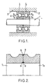
- a rotating shaft 1 included in a device of very high precision (for example a gyrometer of a power station inertial navigation), is rotatably supported in a bore 2 of a support body 3 via a bearing 4 with double bearing.
- a device of very high precision for example a gyrometer of a power station inertial navigation
- the bearing 4 with double bearing is formed by the juxtaposition of two bearings monoroulement: in the example shown, it is constituted by the juxtaposition of two inner rings 5 1 and 5 2 (that is to say mounted on the shaft 1) which respectively retain two annular rows of balls 6 1 and 6 2 in relation respectively to two outer rings 7 1 and 7 2 (that is to say, mounted in the bore 3).
- the detail of the arrangement of the balls with separation cages and other bodies known to those skilled in the art is not shown so as not to complicate the drawing.
- bearing 4 with double bearing and double ring (hereinafter called “composite bearing”) has the same mechanical rigidity characteristics as a one-piece bearing with double bearing, two of the rings, for example the two inner rings 5 1 and 2 , are held together against each other under predetermined preload or preload.
- the two inner rings 5 1 and 5 2 are welded to one another by their cooperating faces, the weld being performed while the two rings are held against each other under said prestressing predetermined value.
- the groove 8 thus formed has a cross section V.
- the weld 9 is then deposited in said groove 8 so that no welding portion protrudes out of the groove 8; the groove 8 must then have a geometry (depth, opening) capable of housing a weld bead suitable for ensuring the required mechanical assembly, without external projection so as not to hinder the subsequent assembly of the double ring.
- the welds are advantageously made by laser, according to techniques known to those skilled in the art.
- the weld bead can be made continuously, especially for external welding, for example when one can continuously rotate all two rings prestressed in front of the laser beam.
- welds be carried out in successive sections, to form a weld bead is continuous in abutting sections or batchwise.
- Such a welding process by sections successive stages is, in particular, implemented for the because of the difficulty of accessing the 8 inner throat, and a specific tool will be presented further to facilitate this work.
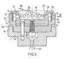
- FIGS. and 5 For the implementation of the welding process two rings held under prestressing, it is proposed, according to the invention, a specific tool including two Embodiments are shown in section in FIGS. and 5, respectively.
- This tool provides support, coaxial centering and preloading of two rings of ball bearing in order to weld them one to the other, while they are maintained under along the inner and / or outer edges of their faces Cooperating.
- the tool generally designated by the reference 10 is shaped for the welding of two inner rings 5 1 , 5 2 held under prestressing.
- the tool 10 comprises a plate 11 having, superiorly, a bowl 12 adapted to retain coaxially a substantially tubular mandrel 13 having a side wall 14 with a cylindrical outer face of revolution which is adapted to support and to coaxially center two rings 5 1 and 5 2 arranged one after the other.
- first axial stop means 15 secured to said mandrel against which a free face of one of the rings 5 1 abuts.
- the first means stop 15 can be carried by a hub 16 which rests in the aforesaid bowl 12 of the plate 11 and which is in a bowl in which is fitted the aforesaid mandrel 13: it is then the annular upper edge of the wall side of said hub 16, which has an outer diameter substantially greater than the outer diameter of said mandrel, which constitutes the aforesaid first stop means 15.
- a piece in the form of a cover 17 whose lateral skirt 18 engages, at a radial distance, the two rings 5 1 , 5 2 and is held coaxially by an outgrowth of the hub 16.
- a clamping member such as a bolt 21 arranged coaxially with its head which bears against the underside of the hub 16 and its rod, which passes through the bottom of said hub, is screwed into the bottom of the mandrel 13.
- the tightening of the bolt 21 makes it possible to subject the two rings 5 1 , 5 2 to a preselectable prestressing.
- one or more pieces 22 are engaged in aligned bores of the base 11, the hub 16 and mandrel 13 to secure them in rotation.
- the mandrel 13 and the cover 17 are arranged as follows.
- the lid 17 is open at 23 in its region Central.
- the mandrel 13 is hollowed out centrally in a bowl at 24 and its side wall 25 is pierced with a multiplicity of through-holes 26 distributed peripherally in a regular manner and opening facing the abutting faces of the two rings 5 1 , 5 2 .
- These lights 26 are inclined downwards radially from the inside to the outside.
- a laser beam can be directed through the opening 23 of the cover and through all the lights 26 successively in the axis thereof, to produce discontinuous weld cords on the inner edges of the cooperating faces of the rings 5. 1 , 5 2 while these rings are maintained under predetermined axial prestressing by clamping the hub and the mandrel.
- the mandrel 13 is rotated around its axis so that all the lights 26 are presented successively to the radius laser.
- the plate 11 is arranged to be rotatively supported (means not shown, schematized by the arrow 27).
- Figure 5 is illustrated another embodiment of the tool, designated as a whole by the reference 28, which is arranged for welding two outer rings 7 1 and 7 2 .
- the general design of the tool 28 remains identical, overall, to that of the tool 10 of FIG. 4, except that it is adapted so that the outer rings 7 1 , 7 2 are supported and centered coaxially by their internal faces.
- the hub 16 has a side wall 29 extended upwards, above and radially outwardly relative to the abutment shoulder 15 above. It is against the face 30, turned towards the inside, of this wall 29 that the rings 7 1 , 7 2 bear against being radially spaced from the side wall 14 of the mandrel 13.
- the side wall 29 of the hub 16 is pierced with a multiplicity of slots 31 distributed around the periphery of said wall 29.
- These substantially radial slots 31 open substantially opposite the outer edges of the cooperating faces of the two outer rings 7 1 , 7 2 : it thus becomes possible to perform the external (discontinuous) welding of the rings 7 1 , 7 2 by directing a laser beam (arrow 32) successively through the slots 31.
- the side wall 14 of the hub 16 As for the side wall 14 of the hub 16, it is extended radially outwards, along its upper edge, by an annular radial flank 33 which extends at least up to the top of the location of the rings 7. 1 , 7 2 .
- an annular radial flank 33 which extends at least up to the top of the location of the rings 7. 1 , 7 2 .
- the side wall 14 of the mandrel 13 retains the aforementioned apertures 26 through which a laser beam can be directed (arrow 34) to reach and weld (discontinuously) the inner edges of the cooperating faces of the two rings 7 1 , 7 2 .
Landscapes
- Engineering & Computer Science (AREA)
- General Engineering & Computer Science (AREA)
- Mechanical Engineering (AREA)
- Physics & Mathematics (AREA)
- Optics & Photonics (AREA)
- Plasma & Fusion (AREA)
- Rolling Contact Bearings (AREA)
- Mounting Of Bearings Or Others (AREA)
- Automatic Assembly (AREA)
Claims (12)
- Verfahren zum Montieren eines zweireihigen Kugellagers zur drehbaren Lagerung einer Drehwelle einer Vorrichtung sehr hoher Genauigkeit,
wobei das zweireihige Lager durch das Aneinanderreihen von zwei einreihigen Lagern aufgebaut ist, bei denen zwei ihrer jeweiligen inneren oder äußeren Hülsen axial gegeneinander gedrückt sind,
dadurch gekennzeichnet, dass es eine Abfolge der folgenden Schritte enthält:zwei einreihige Kugellager werden gepaart, wobei ihre jeweiligen inneren oder äußeren Hülsen zusammenwirkende Flächen mit komplementären Geometrien aufweisen,nach dem Auseinanderbauen der zwei Lager werden deren jeweilige Hülsen gehalten und zentriert auf einem Dorn, der innerhalb der zwei Ringe gelegen ist und mit einer Reihe von peripheren Bohrungen versehen ist, die gegenüber den Innenrändern der zusammenwirkenden Flächen der zwei Hülsen münden, und die zwei jeweiligen oben genannten Hülsen werden gegeneinander positioniert und axial mit einer vorbestimmten Vorspannung gegeneinander gedrückt,ein Verschweißen der zwei jeweiligen Hülsen unter Vorspannung wird durch Leiten eines Laserbündels durch die in dem Dorn vorgesehenen peripheren Bohrungen nacheinander auf nichtkontinuierliche Abschnitte der Innenränder der Hülsen so durchgeführt, dass die Schweißung radial nicht über die ringförmigen Randflächen der Hülsen hinausragt,dann wird das aus den zwei unter Vorspannung verschweißten Hülsen gebildete einstückige Teil auf seinem Stützelement in Position gebracht und die vollständige Montage des Lagers durch das Prinzip des Tiefrillenlagers erzielt. - Verfahren nach Anspruch 1, dadurch gekennzeichnet, dass die Schweißung an aufeinander folgenden Abschnitten gebildet wird.
- Verfahren nach Anspruch 2, dadurch gekennzeichnet, dass die Schweißung an diskontinuierlich aufeinander folgenden Abschnitten gebildet wird.
- Verfahren nach einem der Ansprüche 1 bis 3, dadurch gekennzeichnet, dass die Ränder der jeweiligen Hülsen abgefast sind und
dass die Schweißung auf dem Grund der durch die zwei zusammenwirkenden Abfasungen gebildeten Rinne durchgeführt wird. - Verfahren nach einem der Ansprüche 1 bis 4, dadurch gekennzeichnet, dass die zwei Hülsen entlang ihrer zusammenwirkenden inneren und äußeren Ränder verschweißt sind, und
dass die Schweißung der zusammenwirkenden Innenränder an erster Stelle ausgeführt wird und die Schweißung der zusammenwirkenden Außenränder an zweiter Stelle. - Stützwerkzeug, um zwei Hülsen (51, 52; 71, 72) von Kugellagern, die miteinander verschweißt werden sollen, koaxial zu zentrieren und unter Vorspannung zu bringen, zum Durchführen des Verfahrens nach einem der Ansprüche 1 bis 5 im Hinblick auf das Gewinnen eines zusammengesetzten Lagers,
dadurch gekennzeichnet, dass es enthält:ein erstes axiales Anschlagmittel (15), das mit dem Dorn (13) verbunden ist und gegen das eine freie Fläche eine der zwei Hülsen (51; 71) in Anschlag kommt, undeinen im wesentlichen rohrförmigen Dorn (13), der geeignet ist, koaxial von zwei Hülsen (51, 52; 71, 72) umgeben zu werden, die aufeinanderfolgend angeordnet sind,eine Stützplatine (11) für den Dorn (13), wobei die Platine (11) die Form einer Wanne (12) aufweist, die geeignet ist, koaxial eine Nabe (16) aufzunehmen,die Nabe (16), die eine Seitenwand (29) aufweist, die mit einer Mehrzahl von Durchgangsöffnungen (31) versehen ist, die auf dem Umfang verteilt sind und denen gegenüber die zu schweißenden Ränder der zwei Hülsen (51, 52; 71, 72) liegen, wobei jede Öffnung (31) einen Durchgang bildet, damit ein ihn durchquerendes Laserbündel die gegenüber erscheinenden Ränder der zwei Hülsen (51, 52; 71, 72) verschweißen kann,
ein Mittel (21) zum koaxialen Klemmen des Dorns (13) und der Nabe (15) mit einem zweiten axialen Anschlagmittel (19, 20; 23), das geeignet ist, gegen die freie Fläche der anderen der zwei Hülsen (52; 72) in Anschlag zu kommen, so dass unter der Wirkung des Klemmmittels die zwei Hülsen (51, 52; 71, 72) gegeneinander gedrückt werden bis zum Erzielen eines vorbestimmten Wertes der Vorspannung. - Werkzeug nach Anspruch 6, dadurch gekennzeichnet, dass der Dorn (13) eine Seitenwand (25) mit einer drehzylindrischen Außenfläche (14) enthält, die geeignet ist, zwei Innenhülsen (51; 52), die aufeinanderfolgend angeordnet sind, über ihre Innenflächen zu halten und axial zu zentrieren.
- Werkzeug nach Anspruch 7, dadurch gekennzeichnet, dass das erste Anschlagmittel (15) vorgesehen ist an oder gebildet ist durch den Außenrand der Seitenwand der Nabe (16), und
dass das zweite Anschlagmittel (19; 20) an einer mit dem Dorn (13) verbundenen Abdeckung (19) vorgesehen ist, wobei die Abdeckung (19) in der Mitte (23) offen ist, um das Innere des Dorns zugänglich zu machen. - Werkzeug nach Anspruch 6, dadurch gekennzeichnet, dass die Seitenwand (29) der Nabe (16) eine drehzylindrische Innenfläche (30) aufweist, die geeignet ist, zwei Außenhülsen (71; 72), die aufeinanderfolgend angeordnet sind, über ihre Außenflächen zu halten und axial zu zentrieren.
- Werkzeug nach Anspruch 9, dadurch gekennzeichnet, dass das zweite Anschlagmittel (33) mit dem Dorn (13) verbundenen ist und durch einen Flansch (34) gebildet ist, der radial von dem oberen Rand der Seitenwand (14) des Dorns aus nach außen vorspringt.
- Werkzeug nach einem der Ansprüche 6 bis 10, dadurch gekennzeichnet, dass es ein Mittel zum drehbaren Lagern des Dorns enthält (Pfeil 27).
- Werkzeug nach einem der Ansprüche 6 bis 11, dadurch gekennzeichnet, dass die Öffnungen (26) des Dorns (13) radial vom Inneren zum Äußeren der Wand (25) des Dorns hin nach unten geneigt sind, um die Positionierung des Laserstrahls zum Schweißen annähernd in der Achse jeder Öffnung (26) zu erleichtern.
Applications Claiming Priority (2)
| Application Number | Priority Date | Filing Date | Title |
|---|---|---|---|
| FR0003582A FR2806763B1 (fr) | 2000-03-21 | 2000-03-21 | Palier composite a double roulement a billes, procede pour son montage, et outil pour la realisation d'une paire de bagues dudit palier |
| FR0003582 | 2000-03-21 |
Publications (2)
| Publication Number | Publication Date |
|---|---|
| EP1136713A1 EP1136713A1 (de) | 2001-09-26 |
| EP1136713B1 true EP1136713B1 (de) | 2005-01-19 |
Family
ID=8848321
Family Applications (1)
| Application Number | Title | Priority Date | Filing Date |
|---|---|---|---|
| EP01400461A Expired - Lifetime EP1136713B1 (de) | 2000-03-21 | 2001-02-22 | Zweireihiges Kugelverbundlager,sein Montageverfahren,und Werkzeug zur Herstellung eines Laufringpaares dieses Lagers |
Country Status (5)
| Country | Link |
|---|---|
| US (2) | US6575636B2 (de) |
| EP (1) | EP1136713B1 (de) |
| JP (1) | JP2001311428A (de) |
| DE (1) | DE60108434T2 (de) |
| FR (1) | FR2806763B1 (de) |
Families Citing this family (13)
| Publication number | Priority date | Publication date | Assignee | Title |
|---|---|---|---|---|
| JP2004076901A (ja) * | 2002-08-21 | 2004-03-11 | Minebea Co Ltd | ハードディスクドライブ用ピボットアッセンブリ |
| NL1023883C2 (nl) * | 2003-07-10 | 2005-01-11 | Skf Ab | Lagersamenstel omvattende een gesoldeerde verbinding. |
| NL1024843C2 (nl) | 2003-11-21 | 2005-05-26 | Skf Ab | Lagereenheid met hard gesoldeerde en gelaste verbinding. |
| DE102005034717B4 (de) * | 2005-07-26 | 2021-02-25 | Ab Skf | Abgedichtetes Wälzlager |
| EP1878532B1 (de) * | 2006-07-12 | 2008-09-10 | Federal-Mogul Wiesbaden GmbH | Vorrichtung zum Verbinden von mindestens zwei Bauteilen, Verwendung der Vorrichtung und Aufnahmeelement |
| DE102007004998A1 (de) * | 2007-02-01 | 2008-08-07 | Schaeffler Kg | Drehlageranordnung |
| JP2008298284A (ja) * | 2007-05-01 | 2008-12-11 | Jtekt Corp | ターボチャージャ用軸受装置 |
| JP2009180352A (ja) * | 2008-01-31 | 2009-08-13 | Thk Co Ltd | 運動案内装置の製造方法 |
| US10001028B2 (en) | 2012-04-23 | 2018-06-19 | General Electric Company | Dual spring bearing support housing |
| DE102013207783A1 (de) * | 2013-04-29 | 2014-10-30 | Schaeffler Technologies Gmbh & Co. Kg | Drehverbindung |
| CN108006086B (zh) * | 2017-12-31 | 2023-09-15 | 无锡华洋滚动轴承有限公司 | 自定位等分压装装置 |
| CN112077510B (zh) * | 2020-08-21 | 2022-03-25 | 上海航天精密机械研究所 | 具有同轴保护功能的激光焊接随焊压紧装置及方法 |
| CN115026502B (zh) * | 2022-07-01 | 2024-11-22 | 贵州龙飞航空附件有限公司 | 一种用于球型类结构件的焊接工具及焊接方法 |
Family Cites Families (14)
| Publication number | Priority date | Publication date | Assignee | Title |
|---|---|---|---|---|
| DE166796C (de) * | ||||
| US1441842A (en) * | 1920-08-23 | 1923-01-09 | Rudolph H Fox | Method and apparatus for making ball bearings |
| US3586396A (en) * | 1969-07-25 | 1971-06-22 | Roller Bearing Co Of America | Antifriction carriage roller |
| DE2346679A1 (de) * | 1973-09-17 | 1975-08-07 | Kugelfischer G Schaefer & Co | Waelzlagerlaufringe |
| NL7811624A (nl) * | 1978-11-27 | 1980-05-29 | Skf Ind Trading & Dev | Werkwijze voor het vervaardigen van een voorwerp bestaande uit tenminste twee elementen die beweegbaar ten opzichte van elkaar zijn en waarvan het ene in wezen binnen het andere is opgesloten. |
| US4232914A (en) * | 1979-02-26 | 1980-11-11 | The Torrington Company | Hollow roller tapered bearing |
| US4330911A (en) * | 1979-11-29 | 1982-05-25 | Skf Industrial Trading & Development Co. B.V. | Process for production of an object consisting of at least two parts movable relative to each other, one of which is substantially enclosed within the other |
| NL8701177A (nl) * | 1987-05-15 | 1988-12-01 | Skf Ind Trading & Dev | Werkwijze voor het vervaardigen van een, uit tenminste twee beweegbaar binnen elkaar opgesloten elementen bestaand voorwerp, in het bijzonder een wentellager. |
| DE3902142A1 (de) * | 1989-01-25 | 1990-07-26 | Kugelfischer G Schaefer & Co | Radlagereinheit fuer kraftfahrzeuge |
| US5061090A (en) * | 1990-05-31 | 1991-10-29 | Porter-Cable Corporation | Shaft and bearing assembly |
| NL9400971A (nl) * | 1994-06-14 | 1996-01-02 | Skf Ind Trading & Dev | Lagersamenstel voor een voertuignaaf, alsmede naafsamenstel. |
| JP3054858B2 (ja) * | 1997-05-14 | 2000-06-19 | ミネベア株式会社 | 軸受装置 |
| AU5348298A (en) * | 1997-12-17 | 1999-07-05 | Skf Engineering & Research Centre B.V. | Angular contact bearing unit with one piece inner bearing element |
| US6390681B1 (en) * | 1999-04-05 | 2002-05-21 | Ntn Corporation | Dynamic pressure bearing-unit |
-
2000
- 2000-03-21 FR FR0003582A patent/FR2806763B1/fr not_active Expired - Fee Related
-
2001
- 2001-02-22 DE DE60108434T patent/DE60108434T2/de not_active Expired - Fee Related
- 2001-02-22 EP EP01400461A patent/EP1136713B1/de not_active Expired - Lifetime
- 2001-03-12 US US09/803,363 patent/US6575636B2/en not_active Expired - Fee Related
- 2001-03-16 JP JP2001076379A patent/JP2001311428A/ja not_active Withdrawn
-
2003
- 2003-01-08 US US10/337,882 patent/US6698936B2/en not_active Expired - Fee Related
Also Published As
| Publication number | Publication date |
|---|---|
| FR2806763B1 (fr) | 2002-08-16 |
| US6698936B2 (en) | 2004-03-02 |
| US6575636B2 (en) | 2003-06-10 |
| US20030206673A1 (en) | 2003-11-06 |
| DE60108434D1 (de) | 2005-02-24 |
| FR2806763A1 (fr) | 2001-09-28 |
| DE60108434T2 (de) | 2006-03-30 |
| EP1136713A1 (de) | 2001-09-26 |
| US20010026653A1 (en) | 2001-10-04 |
| JP2001311428A (ja) | 2001-11-09 |
Similar Documents
| Publication | Publication Date | Title |
|---|---|---|
| EP1136713B1 (de) | Zweireihiges Kugelverbundlager,sein Montageverfahren,und Werkzeug zur Herstellung eines Laufringpaares dieses Lagers | |
| EP0579525B1 (de) | Verfahren zur Herstellung einer Fahrradfelge und nach diesem Verfahren hergestellte Felge | |
| EP1816374B1 (de) | Verfahren zur Herstellung eines Reduktionsgetriebes, Reduktionsgetriebe und Roboter, der ein solches Reduktionsgetriebe beinhaltet | |
| CH661110A5 (fr) | Structure demontable. | |
| FR2624419A1 (fr) | Disque d'accouplement electromagnetique et methode de fabrication de celui-ci | |
| FR2638497A1 (fr) | Procede de realisation d'un disque d'accouplement electromagnetique | |
| FR2546966A1 (fr) | Procede de fabrication d'un ensemble d'ailettes de stator soudees pour turbomachine et ensemble en resultant | |
| FR3007807A1 (fr) | Palier a roulement, notamment pour colonne de direction, et procede de fabrication associe | |
| FR3108863A1 (fr) | Broche haute vitesse à assistance vibratoire mécanique forcée | |
| EP3600736B1 (de) | Spannfutter mit geneigten schiebern | |
| EP3063418B1 (de) | Verbindungsanordnung mit einem haltering für eine welle verfahren zur montage solch einer verbindungsanordnung | |
| EP0913595B1 (de) | Herstellungsverfahren eines Innenringes von einem metallischen Kugelgelenk und so erhaltenes Kugelgelenk | |
| FR2612100A1 (fr) | Dispositif de blocage rentrant, pour mandrin de tour ou analogue | |
| FR3111839A1 (fr) | Plateau modulaire circulaire pour la fabrication additive sur lit de poudre d’une pièce à axe de révolution | |
| EP0195474A2 (de) | Flanschbüchsenlager und sein Herstellungsverfahren | |
| EP1423621B1 (de) | Wälzlager für lenksäule | |
| FR3126900A1 (fr) | Procédé d’assemblage d’au moins une bague coopérant par frettage avec une portée de frettage d'une pièce | |
| FR2949858A1 (fr) | Dispositif et procede d'equilibrage | |
| FR2573123A1 (fr) | Joint de belleville soude hermetiquement pour trepan. | |
| EP3115226B1 (de) | Zentrierteil für ein radlager, entsprechendes radlager und entsprechende radanordnung eines fahrzeugs | |
| FR2816231A1 (fr) | Dispositif de serrage de pieces profilees creuses et procede de montage de pieces de type segment et utilisation de celles-ci | |
| EP3608060B1 (de) | Bearbeitungswerkzeug zum schleifen eines werkstücks | |
| EP1569842B1 (de) | Fahrradgabelzusammenbau und lenkkopf auf einem fahrradrahmen und gabel für einen solchen zusammenbau | |
| WO1997027406A1 (fr) | Dispositif pour le guidage en translation et le reglage de l'orientation de deux pieces mobiles l'une par rapport a l'autre | |
| EP0030492B1 (de) | Verfahren und Vorrichtung zum Ausrichten von zwei zylinderförmigen, Rand an Rand zu verbindenden Teilen |
Legal Events
| Date | Code | Title | Description |
|---|---|---|---|
| PUAI | Public reference made under article 153(3) epc to a published international application that has entered the european phase |
Free format text: ORIGINAL CODE: 0009012 |
|
| AK | Designated contracting states |
Kind code of ref document: A1 Designated state(s): DE FR GB IT Kind code of ref document: A1 Designated state(s): AT BE CH CY DE DK ES FI FR GB GR IE IT LI LU MC NL PT SE TR |
|
| AX | Request for extension of the european patent |
Free format text: AL;LT;LV;MK;RO;SI |
|
| 17P | Request for examination filed |
Effective date: 20010803 |
|
| AKX | Designation fees paid |
Free format text: DE FR GB IT |
|
| RAP1 | Party data changed (applicant data changed or rights of an application transferred) |
Owner name: SAGEM S.A. |
|
| 17Q | First examination report despatched |
Effective date: 20040429 |
|
| GRAP | Despatch of communication of intention to grant a patent |
Free format text: ORIGINAL CODE: EPIDOSNIGR1 |
|
| GRAS | Grant fee paid |
Free format text: ORIGINAL CODE: EPIDOSNIGR3 |
|
| GRAA | (expected) grant |
Free format text: ORIGINAL CODE: 0009210 |
|
| AK | Designated contracting states |
Kind code of ref document: B1 Designated state(s): DE FR GB IT |
|
| REG | Reference to a national code |
Ref country code: GB Ref legal event code: FG4D Free format text: NOT ENGLISH |
|
| REF | Corresponds to: |
Ref document number: 60108434 Country of ref document: DE Date of ref document: 20050224 Kind code of ref document: P |
|
| GBT | Gb: translation of ep patent filed (gb section 77(6)(a)/1977) |
Effective date: 20050319 |
|
| PLBE | No opposition filed within time limit |
Free format text: ORIGINAL CODE: 0009261 |
|
| STAA | Information on the status of an ep patent application or granted ep patent |
Free format text: STATUS: NO OPPOSITION FILED WITHIN TIME LIMIT |
|
| 26N | No opposition filed |
Effective date: 20051020 |
|
| REG | Reference to a national code |
Ref country code: FR Ref legal event code: TP |
|
| REG | Reference to a national code |
Ref country code: GB Ref legal event code: 732E |
|
| PGFP | Annual fee paid to national office [announced via postgrant information from national office to epo] |
Ref country code: DE Payment date: 20090227 Year of fee payment: 9 |
|
| PGFP | Annual fee paid to national office [announced via postgrant information from national office to epo] |
Ref country code: GB Payment date: 20090128 Year of fee payment: 9 |
|
| PGFP | Annual fee paid to national office [announced via postgrant information from national office to epo] |
Ref country code: IT Payment date: 20090210 Year of fee payment: 9 |
|
| PGFP | Annual fee paid to national office [announced via postgrant information from national office to epo] |
Ref country code: FR Payment date: 20090226 Year of fee payment: 9 |
|
| GBPC | Gb: european patent ceased through non-payment of renewal fee |
Effective date: 20100222 |
|
| REG | Reference to a national code |
Ref country code: FR Ref legal event code: ST Effective date: 20101029 |
|
| PG25 | Lapsed in a contracting state [announced via postgrant information from national office to epo] |
Ref country code: FR Free format text: LAPSE BECAUSE OF NON-PAYMENT OF DUE FEES Effective date: 20100301 |
|
| PG25 | Lapsed in a contracting state [announced via postgrant information from national office to epo] |
Ref country code: DE Free format text: LAPSE BECAUSE OF NON-PAYMENT OF DUE FEES Effective date: 20100901 |
|
| PG25 | Lapsed in a contracting state [announced via postgrant information from national office to epo] |
Ref country code: GB Free format text: LAPSE BECAUSE OF NON-PAYMENT OF DUE FEES Effective date: 20100222 Ref country code: IT Free format text: LAPSE BECAUSE OF NON-PAYMENT OF DUE FEES Effective date: 20100222 |