EP1136719A1 - Amortisseur de vibrations notamment pour rotor d'hélicoptère - Google Patents
Amortisseur de vibrations notamment pour rotor d'hélicoptère Download PDFInfo
- Publication number
- EP1136719A1 EP1136719A1 EP01400566A EP01400566A EP1136719A1 EP 1136719 A1 EP1136719 A1 EP 1136719A1 EP 01400566 A EP01400566 A EP 01400566A EP 01400566 A EP01400566 A EP 01400566A EP 1136719 A1 EP1136719 A1 EP 1136719A1
- Authority
- EP
- European Patent Office
- Prior art keywords
- damping
- vibration damper
- damper according
- cavity
- main axis
- Prior art date
- Legal status (The legal status is an assumption and is not a legal conclusion. Google has not performed a legal analysis and makes no representation as to the accuracy of the status listed.)
- Granted
Links
- 238000013016 damping Methods 0.000 claims abstract description 53
- 239000012530 fluid Substances 0.000 claims abstract description 20
- 239000012528 membrane Substances 0.000 claims description 16
- 230000000712 assembly Effects 0.000 claims description 3
- 238000000429 assembly Methods 0.000 claims description 3
- 239000006096 absorbing agent Substances 0.000 description 6
- 230000035939 shock Effects 0.000 description 6
- 230000000694 effects Effects 0.000 description 4
- 229920001971 elastomer Polymers 0.000 description 2
- 239000000806 elastomer Substances 0.000 description 2
- 238000013459 approach Methods 0.000 description 1
- 230000000295 complement effect Effects 0.000 description 1
- 230000006835 compression Effects 0.000 description 1
- 238000007906 compression Methods 0.000 description 1
- 230000008602 contraction Effects 0.000 description 1
- 230000003247 decreasing effect Effects 0.000 description 1
- 230000005284 excitation Effects 0.000 description 1
- 230000001747 exhibiting effect Effects 0.000 description 1
- 239000002184 metal Substances 0.000 description 1
- 125000006850 spacer group Chemical group 0.000 description 1
Images


Classifications
-
- B—PERFORMING OPERATIONS; TRANSPORTING
- B64—AIRCRAFT; AVIATION; COSMONAUTICS
- B64C—AEROPLANES; HELICOPTERS
- B64C27/00—Rotorcraft; Rotors peculiar thereto
- B64C27/51—Damping of blade movements
-
- F—MECHANICAL ENGINEERING; LIGHTING; HEATING; WEAPONS; BLASTING
- F16—ENGINEERING ELEMENTS AND UNITS; GENERAL MEASURES FOR PRODUCING AND MAINTAINING EFFECTIVE FUNCTIONING OF MACHINES OR INSTALLATIONS; THERMAL INSULATION IN GENERAL
- F16F—SPRINGS; SHOCK-ABSORBERS; MEANS FOR DAMPING VIBRATION
- F16F1/00—Springs
- F16F1/36—Springs made of rubber or other material having high internal friction, e.g. thermoplastic elastomers
- F16F1/40—Springs made of rubber or other material having high internal friction, e.g. thermoplastic elastomers consisting of a stack of similar elements separated by non-elastic intermediate layers
-
- F—MECHANICAL ENGINEERING; LIGHTING; HEATING; WEAPONS; BLASTING
- F16—ENGINEERING ELEMENTS AND UNITS; GENERAL MEASURES FOR PRODUCING AND MAINTAINING EFFECTIVE FUNCTIONING OF MACHINES OR INSTALLATIONS; THERMAL INSULATION IN GENERAL
- F16F—SPRINGS; SHOCK-ABSORBERS; MEANS FOR DAMPING VIBRATION
- F16F13/00—Units comprising springs of the non-fluid type as well as vibration-dampers, shock-absorbers, or fluid springs
- F16F13/04—Units comprising springs of the non-fluid type as well as vibration-dampers, shock-absorbers, or fluid springs comprising both a plastics spring and a damper, e.g. a friction damper
- F16F13/06—Units comprising springs of the non-fluid type as well as vibration-dampers, shock-absorbers, or fluid springs comprising both a plastics spring and a damper, e.g. a friction damper the damper being a fluid damper, e.g. the plastics spring not forming a part of the wall of the fluid chamber of the damper
- F16F13/08—Units comprising springs of the non-fluid type as well as vibration-dampers, shock-absorbers, or fluid springs comprising both a plastics spring and a damper, e.g. a friction damper the damper being a fluid damper, e.g. the plastics spring not forming a part of the wall of the fluid chamber of the damper the plastics spring forming at least a part of the wall of the fluid chamber of the damper
-
- F—MECHANICAL ENGINEERING; LIGHTING; HEATING; WEAPONS; BLASTING
- F16—ENGINEERING ELEMENTS AND UNITS; GENERAL MEASURES FOR PRODUCING AND MAINTAINING EFFECTIVE FUNCTIONING OF MACHINES OR INSTALLATIONS; THERMAL INSULATION IN GENERAL
- F16F—SPRINGS; SHOCK-ABSORBERS; MEANS FOR DAMPING VIBRATION
- F16F13/00—Units comprising springs of the non-fluid type as well as vibration-dampers, shock-absorbers, or fluid springs
- F16F13/04—Units comprising springs of the non-fluid type as well as vibration-dampers, shock-absorbers, or fluid springs comprising both a plastics spring and a damper, e.g. a friction damper
- F16F13/06—Units comprising springs of the non-fluid type as well as vibration-dampers, shock-absorbers, or fluid springs comprising both a plastics spring and a damper, e.g. a friction damper the damper being a fluid damper, e.g. the plastics spring not forming a part of the wall of the fluid chamber of the damper
- F16F13/08—Units comprising springs of the non-fluid type as well as vibration-dampers, shock-absorbers, or fluid springs comprising both a plastics spring and a damper, e.g. a friction damper the damper being a fluid damper, e.g. the plastics spring not forming a part of the wall of the fluid chamber of the damper the plastics spring forming at least a part of the wall of the fluid chamber of the damper
- F16F13/10—Units comprising springs of the non-fluid type as well as vibration-dampers, shock-absorbers, or fluid springs comprising both a plastics spring and a damper, e.g. a friction damper the damper being a fluid damper, e.g. the plastics spring not forming a part of the wall of the fluid chamber of the damper the plastics spring forming at least a part of the wall of the fluid chamber of the damper the wall being at least in part formed by a flexible membrane or the like
-
- F—MECHANICAL ENGINEERING; LIGHTING; HEATING; WEAPONS; BLASTING
- F16—ENGINEERING ELEMENTS AND UNITS; GENERAL MEASURES FOR PRODUCING AND MAINTAINING EFFECTIVE FUNCTIONING OF MACHINES OR INSTALLATIONS; THERMAL INSULATION IN GENERAL
- F16F—SPRINGS; SHOCK-ABSORBERS; MEANS FOR DAMPING VIBRATION
- F16F13/00—Units comprising springs of the non-fluid type as well as vibration-dampers, shock-absorbers, or fluid springs
- F16F13/04—Units comprising springs of the non-fluid type as well as vibration-dampers, shock-absorbers, or fluid springs comprising both a plastics spring and a damper, e.g. a friction damper
- F16F13/06—Units comprising springs of the non-fluid type as well as vibration-dampers, shock-absorbers, or fluid springs comprising both a plastics spring and a damper, e.g. a friction damper the damper being a fluid damper, e.g. the plastics spring not forming a part of the wall of the fluid chamber of the damper
- F16F13/08—Units comprising springs of the non-fluid type as well as vibration-dampers, shock-absorbers, or fluid springs comprising both a plastics spring and a damper, e.g. a friction damper the damper being a fluid damper, e.g. the plastics spring not forming a part of the wall of the fluid chamber of the damper the plastics spring forming at least a part of the wall of the fluid chamber of the damper
- F16F13/18—Units comprising springs of the non-fluid type as well as vibration-dampers, shock-absorbers, or fluid springs comprising both a plastics spring and a damper, e.g. a friction damper the damper being a fluid damper, e.g. the plastics spring not forming a part of the wall of the fluid chamber of the damper the plastics spring forming at least a part of the wall of the fluid chamber of the damper characterised by the location or the shape of the equilibration chamber, e.g. the equilibration chamber, surrounding the plastics spring or being annular
-
- F—MECHANICAL ENGINEERING; LIGHTING; HEATING; WEAPONS; BLASTING
- F16—ENGINEERING ELEMENTS AND UNITS; GENERAL MEASURES FOR PRODUCING AND MAINTAINING EFFECTIVE FUNCTIONING OF MACHINES OR INSTALLATIONS; THERMAL INSULATION IN GENERAL
- F16F—SPRINGS; SHOCK-ABSORBERS; MEANS FOR DAMPING VIBRATION
- F16F9/00—Springs, vibration-dampers, shock-absorbers, or similarly-constructed movement-dampers using a fluid or the equivalent as damping medium
- F16F9/10—Springs, vibration-dampers, shock-absorbers, or similarly-constructed movement-dampers using a fluid or the equivalent as damping medium using liquid only; using a fluid of which the nature is immaterial
- F16F9/103—Devices with one or more members moving linearly to and fro in chambers, any throttling effect being immaterial, i.e. damping by viscous shear effect only
Definitions
- the subject of the present invention is a vibration damper, especially for rotor helicopter, comprising a leading element having an axis said main axis and intended to be driven by a drive element, as well as a rigid element intended to be mounted on a structure, and comprising a damping assembly functionally connecting the driving element and the rigid element to cushion the vibrations in at least one perpendicular direction said main axis.
- the hydraulic damping device is consisting of a first and a second set of flat blades each of which has its plane perpendicular to the main axis, the first assembly being integral with the driving element and the second set being integral of the rigid element, the blades of the first and second sets being nested and being closely spaced to present areas viscous damping each located between a blade of the first set and a blade of the second set.
- the damping device with flat blades nested as described in the above application allows obtain good performance and good linearity for vibrations of low or medium amplitude.
- the relative speed of the blades also tends to increase, resulting in increased shear and decreased dynamic viscosity, which means that the damping provided by the hydraulic device tends to decrease.
- the present invention proposes to carry out a vibration damper, especially for a rotor helicopter, which has satisfactory damping both for low amplitude travel and high amplitude.
- the basic idea of the invention is to design the damper in such a way that, for low amplitudes, the damping be essentially realized thanks to sets of blades as defined above, while for strong amplitudes, this is a damping type device viscous which complements and / or produces depreciation.
- the vibration damper according to the invention is thus characterized in that the hydraulic device depreciation also has an element damping which is arranged in a said cavity of viscous fluid and which is integral with the driving element, said damping element having a cross section shrinking from a base on the side of a axial end of the shock absorber to a top located on the side of the above-mentioned sets of flat blades.
- the damping element is relatively far from the wall of the cavity (ies) and amortization is mainly provided by blade sets.
- the flexible device tends to warp and as as the amplitudes increase, the external contour at least the damping element approaches locally from the wall of the cavity hence an increase viscous damping effect in the direction where deformation occurs, on the one hand, due to the fact that the passage section narrows and on the other hand, in because of the non-linearity of this effect which, as we have seen above, is proportional to the square of the speed.
- the damping element fits into a maximum deformation contour of the internal surface of the flexible device.
- the external contour of the element depreciation is entered at a predetermined distance of said contour of maximum deformation of the device flexible.
- the external contour of the damping element has a section formed by line segments inclined with respect to said axis main.
- the top of the damping element is elliptical and the base is a circle, or a circle interrupted by segments of right.
- the damping element is hollow and has a volume compensation cavity which communicates with at less a so-called viscous fluid cavity and in which is arranged a volume compensation element, in especially an elastic membrane.
- the membrane elastic does not fold and stays away from inner wall of the damping element.
- the external contour of at least one cavity of viscous fluid can be lengthened in a first direction. At least the base of the damping element can be extended in a second direction perpendicular to the first direction. this allows obtain depreciation characteristics different according to the first and second directions, with more travel in the first direction
- the invention relates a vibration damper, especially for a rotor helicopter, of the type comprising a leading element having an axis called main axis and intended to be driven by a drive element as well as a rigid element intended to be mounted on a structure, and which comprises a damping assembly functionally connecting the driving element and the rigid element to cushion the vibrations in at least one perpendicular direction said main axis, the damping assembly comprising on the one hand a hydraulic device damping arranged in at least one cavity of viscous fluid and secondly a flexible device exhibiting high stiffness in one direction parallel to said main axis and a low stiffness in said direction perpendicular to the main axis.
- a device of this type is described in the French application above and it presents a device volume compensation.
- the devices volume compensation have long been used in hydraulic systems, especially in the form hydraulic accumulators, for example OLAER or LEDUC, and they have also been for a long time in aforementioned vibration dampers.
- the compensation system for volume has a corrugated membrane, one side of which is in contact with the fluid in the cavity and the other of which face is in contact with a cavity containing gas. This device has the disadvantage of some vulnerability of the membrane.
- the invention is proposes to remedy this problem, and to this end the vibration damper is characterized in that it has a volume compensation cavity which communicates with at least one said fluid cavity viscous and inside which is arranged a elastic membrane with an inner wall defining cavity of variable volume filled with a gas, and one of which outer wall, which delimits with an inner wall of said volume compensation cavity, a cavity of compensation fluid, the elastic membrane being disposed at a determined non-zero distance from said internal wall, and without forming a fold, when vibration damper is at minimum temperature of operation provided for by its specifications.
- the compensation cavity is advantageously formed inside a hollow flared piece extending between the hydraulic damping device and a axial end of the shock absorber.
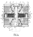
- the vibration damper has a driving element 10 whose ZZ axis is the main axis of the shock absorber and which is intended to be driven by a drive element 100.
- a first set of blades 40 is integral with a close decoupling, of the driving element 10 while a second set of blades 50 nested with the first together is integral, with decoupling near an element rigid 6.
- a decoupling of compression excitations is achieved through a partial overlap of the blades, but this function could be achieved by any other means described in the aforementioned Application FR 2 754 579.
- the structure is symmetrical about a median plane perpendicular to the main axis of the driving element 10.
- the set of blades 40 and 50 is arranged in the middle position and is centered with respect to a flexible device 1 which has a laminated structure consisting of stack of metal washers 4 and washers in elastomer 5 whose plane is perpendicular to the axis of the cylinder 10.
- the laminated structure 1 has an outline internal 11 which delimits the external contour of two cavities 3 located on either side of the assembly of blades 40 and 50 and which are filled with a viscous fluid which also bathes the blades and the space between these so as to provide amortization research.
- the device is closed by covers 80 to which are secured to the damping elements 20 which have a vertex 21 located near the assembly of blades 40 and 50, and a base 23, the top 21 and the base 23 being connected by an outer contour 22 which gradually flares from top 21 to base 23.
- the damping element 20 is hollow and delimits a separate damping cavity in two air 33 and fluid 34 cavities by a membrane 70 housed at its top 71 in the vicinity of an internal face 25 of element 20 and which is pinched at its base 73 between the base 23 of the damping element 20 and the cover 80.
- the membrane 70 has an active region 72 which runs along a flared internal wall 26 which delimits outwardly the cavity 34.
- the fluid cavity 34 communicates with cavity 3 by one or more openings 31 to provide the compensation effect of volume sought.
- the compensation system can be any elastic system, for example a system associating a piston and spring.
- assembly plates 60 located on either side of the blade assemblies 40 and 50 and which have openings 63 (FIG. 1b) of passage of viscous fluid fills the cavities 3. spacers 42 allow the stacking of the cover 80, damping elements 20 and sets 40 and 50 of blades along axis 10 then that on the external part of the complementary flanges 61 and 62 are used for assembly at device level laminated flexible 1 where stacking is also ensured thanks to the cover 80.
- the damping element 20 is preferably produced in the form of a section which has a top 21 having a circular central opening 24 and a substantially elliptical external contour 21 as well as a base 23 having portions of a circle 23 1 connected between them by straight line segments 23 2.
- the external contour 22 has in cross section straight line segments which connect the elliptical contour of the vertex 21 and the contour of the base 23.
- the flared outer contour 22 allows to write element 20 in the contour of the deformations maximum of the laminated device 1 under the conditions of most severe operation, but this with a play which is chosen according to the desired depreciation. Of this fact, it is certain on the one hand that the external contour 22 of damping element 20 will never come in contact with the internal contour 11 of the structures laminated 1 even under the conditions of most severe, and that the element depreciation 20 will bring a damping effect important for large amplitudes.
- the contour 11 which defines the outside of the cavities 3 has an elongated shape limited at the ends by arcs of a circle 11 1 which are connected by straight lines 11 2 .
- XX the major axis of the ellipse 21 and by YY its minor axis and we have plotted these directions in the figure. 3 to indicate the relative position of the part 20 relative to the element 1.
- the section of FIG. 1a is carried out along the plane containing the axis XX and the axis ZZ, while the section of FIG. 1b is carried out along the plane containing the YY axis and the ZZ axis.
- the YY direction corresponds to the largest possible deflections of the damping element.
- the active part 72 of the membrane elastic 70 follows the internal wall 26 of element 20 to a given residual distance and without forming a fold, this which maintains the effectiveness of compensation volume in all operating conditions.
- the membrane 70 occupies the position shown in dotted lines in FIG.
- the viscous fluid contracts, and this contraction produces a decrease of the volume of the cavities 34.
- the membrane 70 does not has no folds, it contracts so uniform and comes along the wall 26 without forming a fold.
- the absence of creases at the minimum temperature of operation prevents the membrane 70 from locally comes into contact with the internal wall 26, this which would decrease the efficiency of volume compensation by isolating part of the fluid cavity 34.
Landscapes
- Engineering & Computer Science (AREA)
- General Engineering & Computer Science (AREA)
- Mechanical Engineering (AREA)
- Architecture (AREA)
- Aviation & Aerospace Engineering (AREA)
- Fluid-Damping Devices (AREA)
- Combined Devices Of Dampers And Springs (AREA)
- Vibration Prevention Devices (AREA)
- Adhesives Or Adhesive Processes (AREA)
Abstract
Description
Claims (10)
- Amortisseur de vibrations, notamment pour rotor d'hélicoptère, comprenant un élément menant (10) ayant un axe dit axe principal et destiné à être entraíné par un élément d'entraínement (100) ainsi qu'un élément rigide (6) destiné à être monté sur une structure, et comportant un ensemble d'amortissement reliant fonctionnellement l'élément menant (10) et l'élément rigide (6) pour amortir les vibrations dans au moins une direction perpendiculaire audit axe principal, l'ensemble d'amortissement comportant d'une part un dispositif hydraulique d'amortissement disposé dans au moins une cavité (3) de fluide visqueux et d'autre part un dispositif flexible (1) présentant une raideur élevée dans une direction parallèle audit axe principal et une faible raideur dans ladite direction perpendiculaire à l'axe principal, le dispositif hydraulique d'amortissement (40, 50) présentant un premier (40) et un deuxième (50) ensembles de lames planes dont chacune a son plan perpendiculaire à l'axe principal, le premier ensemble (40) étant monté sur l'élément menant (10) par l'intermédiaire d'une première liaison mécanique (42) et le deuxième ensemble (50) étant monté sur l'élément rigide (6) par l'intermédiaire d'une deuxième liaison mécanique (60), les lames (40, 50) du premier (40) et du deuxième (50) ensembles étant disposées de manière imbriquée et étant étroitement espacées de manière à présenter des zones d'amortissement visqueux (45) situées chacune entre une lame (40) du premier ensemble et une lame (50) du deuxième ensemble caractérisé en ce que le dispositif hydraulique d'amortissement comporte également au moins un élément d'amortissement (20) qui est disposé dans une dite cavité (3) de fluide visqueux et qui est solidaire de l'élément menant (10), ledit élément d'amortissement (20) présentant un contour externe (22) se rétrécissant depuis une base (23) située du côté d'une extrémité axiale de l'amortisseur jusqu'à un sommet (21) situé du côté des ensembles (40, 50) de lames planes.
- Amortisseur de vibrations selon la revendication 1 caractérisé en ce que le contour extérieur (22) de l'élément d'amortissement (20) s'inscrit dans un contour de déformation maximale de la surface interne (11) du dispositif flexible (1).
- Amortisseur de vibrations selon la revendication 1, caractérisé en ce que le contour extérieur (22) de l'élément d'amortissement est inscrit à une distance prédéterminée dudit contour de déformation maximale.
- Amortisseur de vibrations selon une des revendications précédentes, caractérisé en ce que le contour externe (22) de l'élément d'amortissement présente une section formée par des segments de droite inclinés par rapport audit axe principal (ZZ).
- Amortisseur de vibrations selon une des revendications précédentes, caractérisé en ce que le contour externe d'au moins une cavité (3) de fluide visqueux est allongé selon une première direction (YY) perpendiculaire à l'axe principal (ZZ).
- Amortisseur de vibrations selon la revendication 5, caractérisé en ce qu'au moins la base de l'élément d'amortissement est allongée selon une deuxième direction (XX) perpendiculaire à la première direction(YY)
- Amortisseur de vibrations selon une des revendications 4 à 6, caractérisé en ce que le sommet (21) de l'élément d'amortissement (20)est elliptique et en ce que sa base est un cercle ou un cercle interrompu par des segments de droite.
- Amortisseur de vibrations selon une des revendications précédentes, caractérisé en ce que l'élément d'amortissement (20) est creux et présente une cavité de compensation de volume qui communique avec au moins une dite cavité (3) de fluide visqueux et dans laquelle est disposé un élément de compensation de volume (70).
- Amortisseur de vibrations selon la revendication 8, caractérisé en ce que l'élément de compensation de volume est une membrane élastique (70).
- Amortisseur de vibrations selon la revendication 9, caractérisé en ce que, lorsqu'il est à une température minimale de fonctionnement, la membrane élastique (70) ne présente pas de pli et reste à distance d'une paroi interne (26) de l'élément d'amortissement (20).
Applications Claiming Priority (2)
| Application Number | Priority Date | Filing Date | Title |
|---|---|---|---|
| FR0003525 | 2000-03-20 | ||
| FR0003525A FR2806452B1 (fr) | 2000-03-20 | 2000-03-20 | Amortisseur de vibrations notamment pour rotor d'helicoptere |
Publications (2)
| Publication Number | Publication Date |
|---|---|
| EP1136719A1 true EP1136719A1 (fr) | 2001-09-26 |
| EP1136719B1 EP1136719B1 (fr) | 2003-11-19 |
Family
ID=8848278
Family Applications (1)
| Application Number | Title | Priority Date | Filing Date |
|---|---|---|---|
| EP01400566A Expired - Lifetime EP1136719B1 (fr) | 2000-03-20 | 2001-03-05 | Amortisseur de vibrations notamment pour rotor d'hélicoptère |
Country Status (15)
| Country | Link |
|---|---|
| US (1) | US6938888B2 (fr) |
| EP (1) | EP1136719B1 (fr) |
| JP (1) | JP4540870B2 (fr) |
| KR (1) | KR100797132B1 (fr) |
| CN (1) | CN1288036C (fr) |
| AR (1) | AR027679A1 (fr) |
| AT (1) | ATE254731T1 (fr) |
| CA (1) | CA2341132C (fr) |
| DE (1) | DE60101238T2 (fr) |
| ES (1) | ES2208527T3 (fr) |
| FR (1) | FR2806452B1 (fr) |
| MX (1) | MXPA01002788A (fr) |
| PL (1) | PL201724B1 (fr) |
| RU (1) | RU2256588C2 (fr) |
| TR (1) | TR200400022T4 (fr) |
Cited By (4)
| Publication number | Priority date | Publication date | Assignee | Title |
|---|---|---|---|---|
| KR100797132B1 (ko) * | 2000-03-20 | 2008-01-22 | 허친슨 쏘시에떼 아노님 | 헬리콥터 로터용 진동 댐퍼 |
| CN105650194A (zh) * | 2016-03-07 | 2016-06-08 | 山东大学 | 叶片式耗能调谐减振装置 |
| CN107606052A (zh) * | 2017-09-20 | 2018-01-19 | 株洲时代新材料科技股份有限公司 | 减振支撑装置 |
| EP3462053A1 (fr) * | 2017-09-20 | 2019-04-03 | Zhuzhou Times New Material Technology Co., Ltd | Dispositif de support amortissant les vibrations |
Families Citing this family (17)
| Publication number | Priority date | Publication date | Assignee | Title |
|---|---|---|---|---|
| FR2928344B1 (fr) * | 2008-03-06 | 2011-01-21 | Hutchinson | Dispositif d'amortissement et systeme de rotor d'aerodyne l'incorporant |
| US20110129341A1 (en) * | 2008-07-08 | 2011-06-02 | Prof. Dr.Lars Bertil Carnehammar | Method, apparatus and system for reducing vibration in a rotary system of an aircraft, such as a rotor of a helicopter |
| KR101110608B1 (ko) * | 2009-07-17 | 2012-02-15 | 호남시트주식회사 | 모형 헬리콥터의 로터헤드장치 |
| CN102009745B (zh) * | 2010-11-19 | 2012-12-05 | 中国航空工业集团公司北京航空材料研究院 | 一种直升机旋翼板式阻尼器 |
| US8784057B2 (en) * | 2011-02-28 | 2014-07-22 | The Boeing Company | Disc rotor retraction system |
| US8714226B2 (en) * | 2012-02-27 | 2014-05-06 | The Boeing Company | Automated fiber placement including layup mandrel tool |
| EP2727832B1 (fr) * | 2012-10-31 | 2016-06-22 | AIRBUS HELICOPTERS DEUTSCHLAND GmbH | Tête de rotor d'appareil volante à voilure tournante et son procédé de fabrication et d'assemblage |
| DE102013013092A1 (de) * | 2013-03-25 | 2014-09-25 | Carl Freudenberg Kg | Lager |
| US9951841B2 (en) * | 2013-11-25 | 2018-04-24 | Lord Corporation | Damping fluid devices, systems and methods |
| CN103727173B (zh) * | 2013-11-29 | 2015-10-14 | 辽宁峰阁钛业集团有限公司 | 一种轴端金属减震器 |
| WO2016025491A1 (fr) * | 2014-08-13 | 2016-02-18 | Sikorsky Aircraft Corporation | Dispositif d'amortissement visqueux |
| CN105508488B (zh) * | 2015-12-18 | 2017-12-08 | 南京航空航天大学 | 一种复合型直升机主减周期撑杆 |
| EP3208192B1 (fr) * | 2016-02-22 | 2018-04-11 | LEONARDO S.p.A. | Dispositif d'amortissement de vibrations et méthode d'amortissement pour un rotor d'un aéronef apte à un vol stationnaire |
| CN107630973B (zh) * | 2017-09-20 | 2024-04-09 | 株洲时代新材料科技股份有限公司 | 减振支撑装置 |
| US11339849B2 (en) * | 2017-10-18 | 2022-05-24 | Tongji University | Three-dimensional isolator with adaptive stiffness property |
| US10816035B2 (en) | 2018-12-18 | 2020-10-27 | General Electric Company | Hermetic squeeze film damper having an elliptical damper orifice |
| EP3929078B1 (fr) * | 2020-06-25 | 2022-08-03 | LEONARDO S.p.A. | Hélicoptère |
Citations (2)
| Publication number | Priority date | Publication date | Assignee | Title |
|---|---|---|---|---|
| US5286013A (en) * | 1990-11-13 | 1994-02-15 | General Electric Company | Vibration damper assembly |
| FR2754579A1 (fr) * | 1996-10-15 | 1998-04-17 | Hutchinson | Amortisseur de vibrations, notamment pour rotor d'helicoptere |
Family Cites Families (13)
| Publication number | Priority date | Publication date | Assignee | Title |
|---|---|---|---|---|
| GB1429308A (en) * | 1972-04-17 | 1976-03-24 | Dunlop Ltd | Railway vehicles |
| FR2560322B1 (fr) * | 1984-02-24 | 1986-06-20 | Mte | Dispositif d'appui elastique |
| EP0329788B1 (fr) * | 1987-06-10 | 1993-10-13 | Sugatsune Industrial Co., Ltd. | Amortisseur a plateaux multiples utilisant un fluide visqueux |
| JP2568560B2 (ja) * | 1987-07-02 | 1997-01-08 | 日産自動車株式会社 | 制御型防振装置 |
| US5116201A (en) * | 1991-03-05 | 1992-05-26 | United Technologies Corporation | Adjustment means for helicopter rotor blade viscous damper |
| US5540549A (en) * | 1994-08-05 | 1996-07-30 | Lord Corporation | Fluid damping devices |
| JPH0882333A (ja) * | 1994-09-13 | 1996-03-26 | Unisia Jecs Corp | ロータリダンパ |
| GB2304171A (en) * | 1995-08-08 | 1997-03-12 | Btr Antivibration Syst Inc | Viscous fluid mount |
| US5641153A (en) * | 1995-12-06 | 1997-06-24 | Lord Corporation | Auxiliary damper for rubber suspension mountings |
| JP4038266B2 (ja) * | 1998-02-17 | 2008-01-23 | オイレス工業株式会社 | 粘性せん断型ダンパー |
| US6045328A (en) * | 1998-09-23 | 2000-04-04 | Lord Corporation | Fluid damper including flexible damping plate |
| FR2806452B1 (fr) * | 2000-03-20 | 2002-05-03 | Hutchinson | Amortisseur de vibrations notamment pour rotor d'helicoptere |
| FR2806453B1 (fr) * | 2000-03-20 | 2002-05-03 | Hutchinson | Amortisseur de vibrations notamment pour rotor d'helicoptere |
-
2000
- 2000-03-20 FR FR0003525A patent/FR2806452B1/fr not_active Expired - Fee Related
-
2001
- 2001-03-05 TR TR2004/00022T patent/TR200400022T4/xx unknown
- 2001-03-05 AT AT01400566T patent/ATE254731T1/de not_active IP Right Cessation
- 2001-03-05 EP EP01400566A patent/EP1136719B1/fr not_active Expired - Lifetime
- 2001-03-05 DE DE60101238T patent/DE60101238T2/de not_active Expired - Lifetime
- 2001-03-05 ES ES01400566T patent/ES2208527T3/es not_active Expired - Lifetime
- 2001-03-16 US US09/809,983 patent/US6938888B2/en not_active Expired - Lifetime
- 2001-03-16 PL PL346495A patent/PL201724B1/pl unknown
- 2001-03-16 MX MXPA01002788A patent/MXPA01002788A/es active IP Right Grant
- 2001-03-19 RU RU2001107320/11A patent/RU2256588C2/ru not_active IP Right Cessation
- 2001-03-19 CN CNB011038845A patent/CN1288036C/zh not_active Expired - Fee Related
- 2001-03-19 CA CA002341132A patent/CA2341132C/fr not_active Expired - Fee Related
- 2001-03-19 AR ARP010101266A patent/AR027679A1/es unknown
- 2001-03-19 JP JP2001078421A patent/JP4540870B2/ja not_active Expired - Fee Related
- 2001-03-20 KR KR1020010014315A patent/KR100797132B1/ko not_active Expired - Fee Related
Patent Citations (2)
| Publication number | Priority date | Publication date | Assignee | Title |
|---|---|---|---|---|
| US5286013A (en) * | 1990-11-13 | 1994-02-15 | General Electric Company | Vibration damper assembly |
| FR2754579A1 (fr) * | 1996-10-15 | 1998-04-17 | Hutchinson | Amortisseur de vibrations, notamment pour rotor d'helicoptere |
Cited By (8)
| Publication number | Priority date | Publication date | Assignee | Title |
|---|---|---|---|---|
| KR100797132B1 (ko) * | 2000-03-20 | 2008-01-22 | 허친슨 쏘시에떼 아노님 | 헬리콥터 로터용 진동 댐퍼 |
| CN105650194A (zh) * | 2016-03-07 | 2016-06-08 | 山东大学 | 叶片式耗能调谐减振装置 |
| CN105650194B (zh) * | 2016-03-07 | 2017-11-10 | 山东大学 | 叶片式耗能调谐减振装置 |
| CN107606052A (zh) * | 2017-09-20 | 2018-01-19 | 株洲时代新材料科技股份有限公司 | 减振支撑装置 |
| EP3462053A1 (fr) * | 2017-09-20 | 2019-04-03 | Zhuzhou Times New Material Technology Co., Ltd | Dispositif de support amortissant les vibrations |
| US10677311B2 (en) | 2017-09-20 | 2020-06-09 | Zhuzhou Times New Material Technology Co. Ltd. | Vibration-damping support device |
| EP3770460A1 (fr) | 2017-09-20 | 2021-01-27 | Zhuzhou Times New Material Technology Co., Ltd | Dispositif de support amortissant les vibrations |
| CN107606052B (zh) * | 2017-09-20 | 2024-04-09 | 株洲时代新材料科技股份有限公司 | 减振支撑装置 |
Also Published As
| Publication number | Publication date |
|---|---|
| RU2256588C2 (ru) | 2005-07-20 |
| JP4540870B2 (ja) | 2010-09-08 |
| FR2806452A1 (fr) | 2001-09-21 |
| DE60101238T2 (de) | 2004-09-16 |
| CA2341132C (fr) | 2008-12-30 |
| ATE254731T1 (de) | 2003-12-15 |
| PL346495A1 (en) | 2001-09-24 |
| US20010022418A1 (en) | 2001-09-20 |
| CN1288036C (zh) | 2006-12-06 |
| CN1314287A (zh) | 2001-09-26 |
| ES2208527T3 (es) | 2004-06-16 |
| FR2806452B1 (fr) | 2002-05-03 |
| AR027679A1 (es) | 2003-04-09 |
| PL201724B1 (pl) | 2009-05-29 |
| DE60101238D1 (de) | 2003-12-24 |
| TR200400022T4 (tr) | 2004-03-22 |
| KR100797132B1 (ko) | 2008-01-22 |
| CA2341132A1 (fr) | 2001-09-20 |
| EP1136719B1 (fr) | 2003-11-19 |
| JP2001315697A (ja) | 2001-11-13 |
| KR20010089271A (ko) | 2001-09-29 |
| US6938888B2 (en) | 2005-09-06 |
| MXPA01002788A (es) | 2003-08-20 |
Similar Documents
| Publication | Publication Date | Title |
|---|---|---|
| EP1136719B1 (fr) | Amortisseur de vibrations notamment pour rotor d'hélicoptère | |
| EP2098449B1 (fr) | Dispositif d'amortissement et système de rotor d'aérodyne l'incorporant | |
| EP0205381B1 (fr) | Transducteur électro-fluidique du type buse/palette et servo-valve hydraulique équipée d'un tel transducteur | |
| EP0335786B1 (fr) | Contre-fiche élastique à résonateur hydro-mécanique intégré notamment pour la suspension d'une boîte de transmission sur un giravion, et dispositif de suspension en comportant application | |
| EP2410202B1 (fr) | Dispositif de liaison destiné à relier un premier corps à un second corps, notamment pour ensemble moteur d'aéronef | |
| EP2510236B1 (fr) | Element flexible pour micro-pompe | |
| FR2835506A1 (fr) | Amortisseur de trainee a double piston pour rotor de giravion | |
| FR2915150A1 (fr) | Dispositif d'absorption d'energie pour siege de vehicule automobile,assemblage et ensemble comprenant le dispositif | |
| EP0223712B1 (fr) | Perfectionnements aux amortisseurs hydrauliques | |
| EP2077402B1 (fr) | Amortisseur de vibrations notamment pour structure aerospatiale | |
| WO2011077064A1 (fr) | Vantail pour porte busquee et porte busquee comprenant un tel vantail | |
| EP0837261B1 (fr) | Amortisseur de vibrations, notamment pour rotor d'hélicoptère | |
| FR2743383A1 (fr) | Dispositif d'amortissement pour des elements d'une structure de genie civil | |
| EP0097091B1 (fr) | Amortisseur de vibrations et notamment adaptateur de fréquence pour pale d'hélicoptère | |
| EP1932758B1 (fr) | Revétement absorbant | |
| EP1136354B1 (fr) | Amortisseur de vibrations notamment pour rotor d'hélicoptère | |
| FR2888394A1 (fr) | Dispositif capacitif a volume capacitif optimise | |
| EP0636810B1 (fr) | Perfectionnement aux supports antivibratoires de pales d'hélicoptères et rotor d'hélicoptère comportant de tels supports | |
| WO1997025498A1 (fr) | Dispositif de liaison pour des elements d'une structure de genie civil | |
| EP3207275B1 (fr) | Cale amortissante a systeme hydraulique multi-colonnes | |
| FR2914716A1 (fr) | Butee de compression hydraulique, notamment pour amortisseur hydraulique de suspension de vehicule automobile | |
| EP3985277B1 (fr) | Dispositif d'amortissement amélioré pour engin spatial et procédé de fabrication du dispositif d'amortissement | |
| EP3804117B1 (fr) | Récupérateur d'énergie vibratoire | |
| FR3082072A1 (fr) | Recuperateur d'energie vibratoire | |
| WO2021123543A1 (fr) | Element de decouplage pour un support de moteur comprenant un fluide non newtonien |
Legal Events
| Date | Code | Title | Description |
|---|---|---|---|
| PUAI | Public reference made under article 153(3) epc to a published international application that has entered the european phase |
Free format text: ORIGINAL CODE: 0009012 |
|
| AK | Designated contracting states |
Kind code of ref document: A1 Designated state(s): AT BE CH CY DE DK ES FI FR GB GR IE IT LI LU MC NL PT SE TR |
|
| AX | Request for extension of the european patent |
Free format text: AL;LT;LV;MK;RO;SI |
|
| 17P | Request for examination filed |
Effective date: 20010924 |
|
| AKX | Designation fees paid |
Free format text: AT BE CH CY DE DK ES FI FR GB GR IE IT LI LU MC NL PT SE TR |
|
| GRAH | Despatch of communication of intention to grant a patent |
Free format text: ORIGINAL CODE: EPIDOS IGRA |
|
| GRAS | Grant fee paid |
Free format text: ORIGINAL CODE: EPIDOSNIGR3 |
|
| GRAA | (expected) grant |
Free format text: ORIGINAL CODE: 0009210 |
|
| AK | Designated contracting states |
Kind code of ref document: B1 Designated state(s): AT BE CH CY DE DK ES FI FR GB GR IE IT LI LU MC NL PT SE TR |
|
| PG25 | Lapsed in a contracting state [announced via postgrant information from national office to epo] |
Ref country code: FI Free format text: LAPSE BECAUSE OF FAILURE TO SUBMIT A TRANSLATION OF THE DESCRIPTION OR TO PAY THE FEE WITHIN THE PRESCRIBED TIME-LIMIT Effective date: 20031119 Ref country code: CY Free format text: LAPSE BECAUSE OF FAILURE TO SUBMIT A TRANSLATION OF THE DESCRIPTION OR TO PAY THE FEE WITHIN THE PRESCRIBED TIME-LIMIT Effective date: 20031119 |
|
| REG | Reference to a national code |
Ref country code: GB Ref legal event code: FG4D Free format text: NOT ENGLISH |
|
| REG | Reference to a national code |
Ref country code: CH Ref legal event code: EP |
|
| REF | Corresponds to: |
Ref document number: 60101238 Country of ref document: DE Date of ref document: 20031224 Kind code of ref document: P |
|
| REG | Reference to a national code |
Ref country code: IE Ref legal event code: FG4D Free format text: FRENCH |
|
| PG25 | Lapsed in a contracting state [announced via postgrant information from national office to epo] |
Ref country code: SE Free format text: LAPSE BECAUSE OF FAILURE TO SUBMIT A TRANSLATION OF THE DESCRIPTION OR TO PAY THE FEE WITHIN THE PRESCRIBED TIME-LIMIT Effective date: 20040219 Ref country code: DK Free format text: LAPSE BECAUSE OF FAILURE TO SUBMIT A TRANSLATION OF THE DESCRIPTION OR TO PAY THE FEE WITHIN THE PRESCRIBED TIME-LIMIT Effective date: 20040219 |
|
| REG | Reference to a national code |
Ref country code: GR Ref legal event code: EP Ref document number: 20040400187 Country of ref document: GR |
|
| PG25 | Lapsed in a contracting state [announced via postgrant information from national office to epo] |
Ref country code: LU Free format text: LAPSE BECAUSE OF NON-PAYMENT OF DUE FEES Effective date: 20040305 |
|
| GBT | Gb: translation of ep patent filed (gb section 77(6)(a)/1977) |
Effective date: 20040303 |
|
| PG25 | Lapsed in a contracting state [announced via postgrant information from national office to epo] |
Ref country code: MC Free format text: LAPSE BECAUSE OF NON-PAYMENT OF DUE FEES Effective date: 20040331 Ref country code: BE Free format text: LAPSE BECAUSE OF NON-PAYMENT OF DUE FEES Effective date: 20040331 |
|
| REG | Reference to a national code |
Ref country code: ES Ref legal event code: FG2A Ref document number: 2208527 Country of ref document: ES Kind code of ref document: T3 |
|
| PLBE | No opposition filed within time limit |
Free format text: ORIGINAL CODE: 0009261 |
|
| STAA | Information on the status of an ep patent application or granted ep patent |
Free format text: STATUS: NO OPPOSITION FILED WITHIN TIME LIMIT |
|
| BERE | Be: lapsed |
Owner name: *HUTCHINSON Effective date: 20040331 |
|
| 26N | No opposition filed |
Effective date: 20040820 |
|
| PG25 | Lapsed in a contracting state [announced via postgrant information from national office to epo] |
Ref country code: CH Free format text: LAPSE BECAUSE OF NON-PAYMENT OF DUE FEES Effective date: 20050331 Ref country code: LI Free format text: LAPSE BECAUSE OF NON-PAYMENT OF DUE FEES Effective date: 20050331 |
|
| REG | Reference to a national code |
Ref country code: CH Ref legal event code: PL |
|
| PG25 | Lapsed in a contracting state [announced via postgrant information from national office to epo] |
Ref country code: PT Free format text: LAPSE BECAUSE OF NON-PAYMENT OF DUE FEES Effective date: 20040419 |
|
| PGFP | Annual fee paid to national office [announced via postgrant information from national office to epo] |
Ref country code: IE Payment date: 20080321 Year of fee payment: 8 |
|
| PGFP | Annual fee paid to national office [announced via postgrant information from national office to epo] |
Ref country code: AT Payment date: 20080321 Year of fee payment: 8 |
|
| PGFP | Annual fee paid to national office [announced via postgrant information from national office to epo] |
Ref country code: GR Payment date: 20080326 Year of fee payment: 8 |
|
| PG25 | Lapsed in a contracting state [announced via postgrant information from national office to epo] |
Ref country code: AT Free format text: LAPSE BECAUSE OF NON-PAYMENT OF DUE FEES Effective date: 20090305 |
|
| REG | Reference to a national code |
Ref country code: IE Ref legal event code: MM4A |
|
| PG25 | Lapsed in a contracting state [announced via postgrant information from national office to epo] |
Ref country code: IE Free format text: LAPSE BECAUSE OF NON-PAYMENT OF DUE FEES Effective date: 20090305 |
|
| PG25 | Lapsed in a contracting state [announced via postgrant information from national office to epo] |
Ref country code: GR Free format text: LAPSE BECAUSE OF NON-PAYMENT OF DUE FEES Effective date: 20091002 |
|
| PGFP | Annual fee paid to national office [announced via postgrant information from national office to epo] |
Ref country code: TR Payment date: 20100223 Year of fee payment: 10 |
|
| PGFP | Annual fee paid to national office [announced via postgrant information from national office to epo] |
Ref country code: NL Payment date: 20100401 Year of fee payment: 10 |
|
| REG | Reference to a national code |
Ref country code: NL Ref legal event code: V1 Effective date: 20111001 |
|
| PG25 | Lapsed in a contracting state [announced via postgrant information from national office to epo] |
Ref country code: NL Free format text: LAPSE BECAUSE OF NON-PAYMENT OF DUE FEES Effective date: 20111001 |
|
| PG25 | Lapsed in a contracting state [announced via postgrant information from national office to epo] |
Ref country code: TR Free format text: LAPSE BECAUSE OF NON-PAYMENT OF DUE FEES Effective date: 20110305 |
|
| REG | Reference to a national code |
Ref country code: FR Ref legal event code: PLFP Year of fee payment: 15 |
|
| REG | Reference to a national code |
Ref country code: FR Ref legal event code: PLFP Year of fee payment: 16 |
|
| REG | Reference to a national code |
Ref country code: FR Ref legal event code: PLFP Year of fee payment: 17 |
|
| PGFP | Annual fee paid to national office [announced via postgrant information from national office to epo] |
Ref country code: FR Payment date: 20170227 Year of fee payment: 17 Ref country code: DE Payment date: 20170322 Year of fee payment: 17 |
|
| PGFP | Annual fee paid to national office [announced via postgrant information from national office to epo] |
Ref country code: GB Payment date: 20170322 Year of fee payment: 17 |
|
| PGFP | Annual fee paid to national office [announced via postgrant information from national office to epo] |
Ref country code: ES Payment date: 20170315 Year of fee payment: 17 |
|
| PGFP | Annual fee paid to national office [announced via postgrant information from national office to epo] |
Ref country code: IT Payment date: 20170323 Year of fee payment: 17 |
|
| REG | Reference to a national code |
Ref country code: DE Ref legal event code: R119 Ref document number: 60101238 Country of ref document: DE |
|
| GBPC | Gb: european patent ceased through non-payment of renewal fee |
Effective date: 20180305 |
|
| PG25 | Lapsed in a contracting state [announced via postgrant information from national office to epo] |
Ref country code: DE Free format text: LAPSE BECAUSE OF NON-PAYMENT OF DUE FEES Effective date: 20181002 |
|
| PG25 | Lapsed in a contracting state [announced via postgrant information from national office to epo] |
Ref country code: GB Free format text: LAPSE BECAUSE OF NON-PAYMENT OF DUE FEES Effective date: 20180305 Ref country code: IT Free format text: LAPSE BECAUSE OF NON-PAYMENT OF DUE FEES Effective date: 20180305 |
|
| PG25 | Lapsed in a contracting state [announced via postgrant information from national office to epo] |
Ref country code: FR Free format text: LAPSE BECAUSE OF NON-PAYMENT OF DUE FEES Effective date: 20180331 |
|
| REG | Reference to a national code |
Ref country code: ES Ref legal event code: FD2A Effective date: 20190904 |
|
| PG25 | Lapsed in a contracting state [announced via postgrant information from national office to epo] |
Ref country code: ES Free format text: LAPSE BECAUSE OF NON-PAYMENT OF DUE FEES Effective date: 20180306 |