EP1136725B1 - Mécanisme d'avance par vis à billes - Google Patents
Mécanisme d'avance par vis à billes Download PDFInfo
- Publication number
- EP1136725B1 EP1136725B1 EP01105261A EP01105261A EP1136725B1 EP 1136725 B1 EP1136725 B1 EP 1136725B1 EP 01105261 A EP01105261 A EP 01105261A EP 01105261 A EP01105261 A EP 01105261A EP 1136725 B1 EP1136725 B1 EP 1136725B1
- Authority
- EP
- European Patent Office
- Prior art keywords
- ball screw
- axial direction
- plate
- section
- feed mechanism
- Prior art date
- Legal status (The legal status is an assumption and is not a legal conclusion. Google has not performed a legal analysis and makes no representation as to the accuracy of the status listed.)
- Expired - Lifetime
Links
- 238000006073 displacement reaction Methods 0.000 claims description 12
- 230000002093 peripheral effect Effects 0.000 claims description 7
- 230000006835 compression Effects 0.000 description 12
- 238000007906 compression Methods 0.000 description 12
- 239000000463 material Substances 0.000 description 10
- 238000007599 discharging Methods 0.000 description 8
- 210000000078 claw Anatomy 0.000 description 7
- 230000000694 effects Effects 0.000 description 3
- 238000003780 insertion Methods 0.000 description 3
- 230000037431 insertion Effects 0.000 description 3
- 238000007639 printing Methods 0.000 description 3
- 238000005516 engineering process Methods 0.000 description 2
- 238000007665 sagging Methods 0.000 description 2
- 238000013459 approach Methods 0.000 description 1
- 238000005452 bending Methods 0.000 description 1
- 238000001514 detection method Methods 0.000 description 1
Images





Classifications
-
- F—MECHANICAL ENGINEERING; LIGHTING; HEATING; WEAPONS; BLASTING
- F16—ENGINEERING ELEMENTS AND UNITS; GENERAL MEASURES FOR PRODUCING AND MAINTAINING EFFECTIVE FUNCTIONING OF MACHINES OR INSTALLATIONS; THERMAL INSULATION IN GENERAL
- F16H—GEARING
- F16H25/00—Gearings comprising primarily only cams, cam-followers and screw-and-nut mechanisms
- F16H25/18—Gearings comprising primarily only cams, cam-followers and screw-and-nut mechanisms for conveying or interconverting oscillating or reciprocating motions
- F16H25/20—Screw mechanisms
- F16H25/22—Screw mechanisms with balls, rollers, or similar members between the co-operating parts; Elements essential to the use of such members
- F16H25/2204—Screw mechanisms with balls, rollers, or similar members between the co-operating parts; Elements essential to the use of such members with balls
-
- B—PERFORMING OPERATIONS; TRANSPORTING
- B23—MACHINE TOOLS; METAL-WORKING NOT OTHERWISE PROVIDED FOR
- B23Q—DETAILS, COMPONENTS, OR ACCESSORIES FOR MACHINE TOOLS, e.g. ARRANGEMENTS FOR COPYING OR CONTROLLING; MACHINE TOOLS IN GENERAL CHARACTERISED BY THE CONSTRUCTION OF PARTICULAR DETAILS OR COMPONENTS; COMBINATIONS OR ASSOCIATIONS OF METAL-WORKING MACHINES, NOT DIRECTED TO A PARTICULAR RESULT
- B23Q11/00—Accessories fitted to machine tools for keeping tools or parts of the machine in good working condition or for cooling work; Safety devices specially combined with or arranged in, or specially adapted for use in connection with, machine tools
- B23Q11/0032—Arrangements for preventing or isolating vibrations in parts of the machine
- B23Q11/0039—Arrangements for preventing or isolating vibrations in parts of the machine by changing the natural frequency of the system or by continuously changing the frequency of the force which causes the vibration
-
- F—MECHANICAL ENGINEERING; LIGHTING; HEATING; WEAPONS; BLASTING
- F16—ENGINEERING ELEMENTS AND UNITS; GENERAL MEASURES FOR PRODUCING AND MAINTAINING EFFECTIVE FUNCTIONING OF MACHINES OR INSTALLATIONS; THERMAL INSULATION IN GENERAL
- F16H—GEARING
- F16H57/00—General details of gearing
- F16H57/0006—Vibration-damping or noise reducing means specially adapted for gearings
-
- Y—GENERAL TAGGING OF NEW TECHNOLOGICAL DEVELOPMENTS; GENERAL TAGGING OF CROSS-SECTIONAL TECHNOLOGIES SPANNING OVER SEVERAL SECTIONS OF THE IPC; TECHNICAL SUBJECTS COVERED BY FORMER USPC CROSS-REFERENCE ART COLLECTIONS [XRACs] AND DIGESTS
- Y10—TECHNICAL SUBJECTS COVERED BY FORMER USPC
- Y10T—TECHNICAL SUBJECTS COVERED BY FORMER US CLASSIFICATION
- Y10T74/00—Machine element or mechanism
- Y10T74/18—Mechanical movements
- Y10T74/18568—Reciprocating or oscillating to or from alternating rotary
- Y10T74/18576—Reciprocating or oscillating to or from alternating rotary including screw and nut
- Y10T74/1868—Deflection related
-
- Y—GENERAL TAGGING OF NEW TECHNOLOGICAL DEVELOPMENTS; GENERAL TAGGING OF CROSS-SECTIONAL TECHNOLOGIES SPANNING OVER SEVERAL SECTIONS OF THE IPC; TECHNICAL SUBJECTS COVERED BY FORMER USPC CROSS-REFERENCE ART COLLECTIONS [XRACs] AND DIGESTS
- Y10—TECHNICAL SUBJECTS COVERED BY FORMER USPC
- Y10T—TECHNICAL SUBJECTS COVERED BY FORMER US CLASSIFICATION
- Y10T74/00—Machine element or mechanism
- Y10T74/18—Mechanical movements
- Y10T74/18568—Reciprocating or oscillating to or from alternating rotary
- Y10T74/18576—Reciprocating or oscillating to or from alternating rotary including screw and nut
- Y10T74/18728—Backlash
-
- Y—GENERAL TAGGING OF NEW TECHNOLOGICAL DEVELOPMENTS; GENERAL TAGGING OF CROSS-SECTIONAL TECHNOLOGIES SPANNING OVER SEVERAL SECTIONS OF THE IPC; TECHNICAL SUBJECTS COVERED BY FORMER USPC CROSS-REFERENCE ART COLLECTIONS [XRACs] AND DIGESTS
- Y10—TECHNICAL SUBJECTS COVERED BY FORMER USPC
- Y10T—TECHNICAL SUBJECTS COVERED BY FORMER US CLASSIFICATION
- Y10T74/00—Machine element or mechanism
- Y10T74/19—Gearing
- Y10T74/19642—Directly cooperating gears
- Y10T74/19698—Spiral
- Y10T74/19702—Screw and nut
Definitions
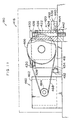
- the urging device urges the ball screw in the direction opposite to this displacement in an attempt to forcibly return the ball screw to its original position. In this way, the resonance point is forcibly shifted. The vibration of the ball screw is thereby mitigated, and accordingly, the vibration of the slider is reduced.
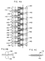
- each conveying section As illustrated in Fig. 5, at the transfer ("hand-over") portion of each conveying section, the respective distal end portions project out alternately in skewer shapes, such that the distal end of one concave portion or one convex portion opposes the distal end of a convex portion or a concave portion. (In other words, a coaxial, common conveying path is formed.)
- the problem of the photopolymer plate 102 or the interleaf sheet 118 becoming wound up by the skewer rollers 138 or the thin belts 140 can be prevented in advance.
- the interleaf sheet accommodating section 132 is provided within the stand 200.
- the interleaf sheet accommodating section 132 accommodates the interleaf sheets 118 which are conveyed by the interleaf sheet conveying section 134 which will be described hereinafter.
- a sheet material forcibly stacking device 141 is provided at the upper end portion of the interleaf sheet accommodating section 132 in the stand 200. The sheet material forcibly stacking device 141 forcibly stacks, in the interleaf sheet accommodating section 132, the interleaf sheets 118 which are conveyed by the interleaf sheet conveying section 134.
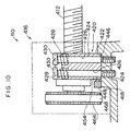
- a supporting section 416 is provided at this other longitudinal direction end portion of the ball screw 412.
- the supporting section 416 includes a supporting stand 418.
- a casing 422 of a ball bearing 420 is disposed on the supporting stand 418.
- a hole, which passes through along the axial direction of the ball screw 412, is formed in the casing 422. This other axial direction end side of the ball screw 412 passes through the hole.
- a plurality of small spheres are aligned along the peripheral direction of the ball screw 412 so as to abut the ball screw 412 at the inner side of the casing 422.
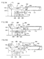
- the roller 180 of the moving stage 178 abutting the convex portion 172 of the temporarily supporting arm 154 and the temporarily supporting arm 154 being set at a horizontal position at the same height as the surface plate 402, sagging of the photopolymer plate 102 on the surface plate 402 can be prevented. Further, due to the roller 180 of the moving stage 178 abutting the convex portion 176 of the temporarily supporting arm 154 and the temporarily supporting arm 154 being set at a pushed up position which is higher than the surface plate 402, the rear end portion of the photopolymer plate 102 on the surface plate 402 can be raised up.
Landscapes
- Engineering & Computer Science (AREA)
- General Engineering & Computer Science (AREA)
- Mechanical Engineering (AREA)
- Exposure And Positioning Against Photoresist Photosensitive Materials (AREA)
- Transmission Devices (AREA)
- Sheets, Magazines, And Separation Thereof (AREA)
- Vibration Prevention Devices (AREA)
Claims (10)
- Mécanisme d'avance par vis à billes, comprenant :caractérisé en ce que ladite partie de support supporte le ladite portion terminale de la vis à billes (412) de telle façon que la vis à billes est déplaçable le long d'une seule direction axiale de la vis à billes dans un sens, etune vis à billes (412) en forme de tige, à la partie périphérique extérieure de celle-ci étant formée une vis mâle, et qui tourne autour d'un arbre de la vis à billes (412) en raison de la force d'entraínement d'un dispositif d'entraínement (460) ;un coolisseau (472) qui est vissé ensemble avec la vis à billes (412) etqui coulisse le long d'une direction axiale de la vis à billes (412) en raison de la rotation de la vis à billes (412) autour de l'axe de la vis à billes (412) ;une partie de support qui supporte la vis à billes (412) au niveau d'une portion terminale en direction axiale de la vis à billes,
en ce qu'un dispositif de sollicitation (450) sollicite la vis à billes dans une direction opposée à une direction de déplacement, par rapport au déplacement de la vis à billes le long de ladite direction axiale de la vis à billes. - Mécanisme d'avance par vis à billes, selon la revendication 1, dans lequel ladite partie de support inclut :un banc de support (418) qui est sensiblement parallèle à la direction axiale de la vis à billes ;une partie de butée (420, 422) contre laquelle la vis à billes vient buter avec faculté de rotation ; etun arbre (424), une extrémité dudit arbre étant fixée au banc de support (418) de telle façon que la partie de butée (420, 422) soit supportée au niveau du banc de support (418).
- Mécanisme d'avance par vis à billes, selon l'une ou l'autre des revendications 1 et 2, dans lequel le dispositif de sollicitation inclut :un bras (448) qui est disposé sensiblement perpendiculairement à la direction axiale de la vis à billes, une extrémité du bras étant montée en pivotement ; etune partie de sollicitation (450), ancrée sur ladite extrémité pivotante du bras, sensiblement parallèle à la direction axiale de la vis à billes.
- Mécanisme d'avance par vis à billes selon la revendication 3, dans lequel la partie de butée (420, 422) inclut :une partie de portée (420) en butée contre la partie périphérique extérieure de la vis à billes ; etun boítier (422) disposé sur le banc de support (418).
- Mécanisme d'avance par vis à billes selon la revendication 2, dans lequel une bride (430) est formée à une autre extrémité de l'arbre (424), et une partie de sollicitation (428) qui sollicite la partie de butée (422) vers le banc de support (418) est montée sur la bride (430).
- Mécanisme d'avance par vis à billes, comprenant :caractérisé en ce que ladite partie de support supporte la portion terminale de la vis à billes (412) de telle manière que la vis à billes est déplaçable le long d'au moins une direction perpendiculaire à la direction axiale de la vis à billes ; etune vis à billes (412) en forme de tige, à la partie périphérique extérieure de celle-ci étant formée une vis mâle, qui tourne autour d'un arbre de la vis à billes (412) en raison de la force d'entraínement d'un dispositif d'entraínement ;un coulisseau (472) qui est vissé ensemble avec la vis à billes (412) etqui coulisse le long d'une direction axiale de la vis à billes (412) en raison de la rotation de la vis à billes (412) autour de l'axe de la vis à billes (412) ;une partie de support (418, 432, 436) qui supporte la vis à billes (412) au niveau d'une portion terminale en direction axiale de la vis à billes,
en ce qu'un dispositif de sollicitation (428, 436) sollicite la vis à billes dans une direction opposée à ladite au moins une direction de déplacement, par rapport au déplacement de la vis à billes le long de ladite au moins une direction perpendiculaire à la direction axiale de la vis à billes. - Mécanisme d'avance par vis à billes, selon la revendication 6, dans lequel la partie de support (418, 432, 436) inclut :un banc de support (418) qui est sensiblement parallèle à la direction axiale de la vis à billes ;une partie de butée (420, 422) contre laquelle vient buter la vis à billes avec faculté de rotation ; etun arbre (424), une extrémité de l'arbre étant fixée sur le banc de support (418) de telle façon que la partie de butée (420, 422) soit supportée sur le banc de support (418).
- Mécanisme d'avance par vis à billes, selon la revendication 7, dans lequel la partie de butée (420, 422) inclut :une partie de portée (420) en butée contre la partie périphérique extérieure de la vis à billes ; etun boítier (422) disposé sur le banc de support (418).
- Mécanisme d'avance par vis à billes, selon la revendication 8, dans lequel le dispositif de sollicitation (436) inclut :une partie de pressage (436) fixée sur le banc de support (418) ;une parue de sollicitation (444) dont une extrémité est montée sur l'intérieur de la partie de pressage (436) et dont l'autre extrémité sollicite le boítier, etune partie de limitation (436) fixée sur le banc de support (418) de telle façon que le boítier (422) est pris en sandwich entre et en butée par la partie de limitation (432) et par la partie de pressage (436).
- Mécanisme d'avance par vis à billes, selon l'une quelconque des revendications 7 à 9, dans lequel le dispositif de sollicitation (428) inclut :une bride (430) formée à une autre extrémité de l'arbre (424) ; etune partie de sollicitation (428) montée sur la bride (430) et sollicitant la partie de butée (422) vers le banc de support (418).
Applications Claiming Priority (2)
| Application Number | Priority Date | Filing Date | Title |
|---|---|---|---|
| JP2000062665A JP2001248704A (ja) | 2000-03-07 | 2000-03-07 | ボールねじ送り機構 |
| JP2000062665 | 2000-03-07 |
Publications (2)
| Publication Number | Publication Date |
|---|---|
| EP1136725A1 EP1136725A1 (fr) | 2001-09-26 |
| EP1136725B1 true EP1136725B1 (fr) | 2003-02-19 |
Family
ID=18582640
Family Applications (1)
| Application Number | Title | Priority Date | Filing Date |
|---|---|---|---|
| EP01105261A Expired - Lifetime EP1136725B1 (fr) | 2000-03-07 | 2001-03-05 | Mécanisme d'avance par vis à billes |
Country Status (4)
| Country | Link |
|---|---|
| US (1) | US6564660B2 (fr) |
| EP (1) | EP1136725B1 (fr) |
| JP (1) | JP2001248704A (fr) |
| DE (1) | DE60100103T2 (fr) |
Cited By (1)
| Publication number | Priority date | Publication date | Assignee | Title |
|---|---|---|---|---|
| TWI465707B (zh) * | 2011-11-07 | 2014-12-21 | Univ Nat Changhua Education | 利用振動訊號、聲紋訊號診斷滾珠導螺桿預壓力失調之量測系統及其方法 |
Families Citing this family (5)
| Publication number | Priority date | Publication date | Assignee | Title |
|---|---|---|---|---|
| US6795483B1 (en) * | 2000-08-28 | 2004-09-21 | Komatsu, Ltd. | Optical component driving device in laser apparatus |
| CN103508031B (zh) * | 2012-06-22 | 2015-11-18 | 日本通运株式会社 | 货物输送用托盘装置 |
| US9182022B2 (en) | 2012-10-17 | 2015-11-10 | Honeywell International Inc. | Ball screw actuator including a stop with an integral guide |
| CN115781382B (zh) * | 2022-10-17 | 2025-10-21 | 北京机械设备研究所 | 一种丝杠传动振动控制系统及其控制方法 |
| CN119733873B (zh) * | 2025-02-08 | 2025-11-11 | 上海舜锋机械制造有限公司 | 一种用于碳钢不锈钢复合板的铣削装置 |
Family Cites Families (17)
| Publication number | Priority date | Publication date | Assignee | Title |
|---|---|---|---|---|
| US331311A (en) * | 1885-12-01 | geoege marquardt | ||
| US1879357A (en) * | 1930-07-30 | 1932-09-27 | See Elevator Company Inc Ab | Bearing |
| CH519125A (de) * | 1970-01-16 | 1972-02-15 | Haller Richard | Vorrichtung zur gegenseitigen axialen Verschiebung einer Welle oder Gewindespindel oder Zahnstange einerseits und eines darauf angeordneten Elementes anderseits |
| US3959898A (en) * | 1971-11-04 | 1976-06-01 | Mcwatters William Andrew | Dredge ladder shock mounting arrangement |
| US3792619A (en) * | 1972-08-31 | 1974-02-19 | R Cannon | Constant tension ball screw feed design |
| DE3125721A1 (de) * | 1981-06-30 | 1983-01-13 | Bosch-Siemens Hausgeräte GmbH, 7000 Stuttgart | Antriebseinrichtung, vorzugsweise elektromotor fuer umluftgeblaese von backoefen |
| JPS6041665U (ja) * | 1983-08-31 | 1985-03-23 | 松下電器産業株式会社 | 駆動装置 |
| US4802558A (en) * | 1987-10-01 | 1989-02-07 | The Olofsson Corporation | Apparatus providing environmental and mechanical protection for ball screw drives |
| JPH03103614A (ja) * | 1989-09-16 | 1991-04-30 | Canon Inc | すべり軸受 |
| JPH0373747U (fr) * | 1989-11-21 | 1991-07-24 | ||
| JPH0386238U (fr) * | 1989-12-25 | 1991-08-30 | ||
| JP3103614B2 (ja) | 1991-06-04 | 2000-10-30 | オリンパス光学工業株式会社 | 超音波手術用ハンドピース |
| EP0601185B1 (fr) * | 1991-09-04 | 1997-03-12 | Smc Kabushiki Kaisha | Actuateur |
| US5613400A (en) * | 1994-01-18 | 1997-03-25 | Nsk Ltd. | Ball screw device with resonance preventing means for a screw shaft and table drive device including the same |
| US5482416A (en) * | 1994-06-30 | 1996-01-09 | Reko International Group Inc. | Metal working machine |
| JPH0871881A (ja) * | 1994-08-31 | 1996-03-19 | Murata Mach Ltd | ボールねじを含む送り機構 |
| FI102206B1 (fi) * | 1995-09-21 | 1998-10-30 | Orion Yhtymae Oy | Siirtolaite |
-
2000
- 2000-03-07 JP JP2000062665A patent/JP2001248704A/ja active Pending
-
2001
- 2001-03-05 EP EP01105261A patent/EP1136725B1/fr not_active Expired - Lifetime
- 2001-03-05 DE DE60100103T patent/DE60100103T2/de not_active Expired - Lifetime
- 2001-03-07 US US09/799,559 patent/US6564660B2/en not_active Expired - Fee Related
Cited By (1)
| Publication number | Priority date | Publication date | Assignee | Title |
|---|---|---|---|---|
| TWI465707B (zh) * | 2011-11-07 | 2014-12-21 | Univ Nat Changhua Education | 利用振動訊號、聲紋訊號診斷滾珠導螺桿預壓力失調之量測系統及其方法 |
Also Published As
| Publication number | Publication date |
|---|---|
| JP2001248704A (ja) | 2001-09-14 |
| DE60100103T2 (de) | 2003-07-31 |
| US6564660B2 (en) | 2003-05-20 |
| DE60100103D1 (de) | 2003-03-27 |
| EP1136725A1 (fr) | 2001-09-26 |
| US20030019314A1 (en) | 2003-01-30 |
Similar Documents
| Publication | Publication Date | Title |
|---|---|---|
| US6619208B2 (en) | Conveying device using suction adherence for printing plates | |
| EP1136725B1 (fr) | Mécanisme d'avance par vis à billes | |
| EP1085382B1 (fr) | Procédé de positionnement et dispositif de positionnement | |
| US6623003B1 (en) | Sheet material stacking device and automatic exposure device for a printing plate | |
| JP2001261196A (ja) | シート材位置決め方法及び装置 | |
| US6935238B2 (en) | Image recording material conveying device and automatic image recording system | |
| US6800868B2 (en) | Device for discriminating among print media | |
| JP3101344B2 (ja) | シート分離機構及びこれを用いたシステム | |
| US6675711B2 (en) | Apparatus for feeding and ejecting a printing plate onto a surface plate | |
| US6457414B1 (en) | Printing plate discharging method and printing plate discharging device | |
| JP2003076032A (ja) | 印刷版の搬送案内装置 | |
| US6624840B1 (en) | Automatic exposure apparatus for printing plates and method for exposing printing plates | |
| JP2001247228A (ja) | シート材の検出装置 | |
| JP2001151360A (ja) | 印刷版の吸着搬送装置 | |
| JP3329427B2 (ja) | フィルム収納シート取扱装置及び取扱方法 | |
| JP2001092145A (ja) | 印刷版の塵除去装置 | |
| JP2808017B2 (ja) | 用紙記録装置の排紙装置 | |
| JP2001261179A (ja) | 搬送装置 | |
| JP2001092141A (ja) | 印刷版自動露光装置、印刷版運搬用台車及び印刷版自動露光装置用台車の受け渡し構造 | |
| JP2001249464A (ja) | 印刷版搬送装置 | |
| JP2001151395A (ja) | シート材強制集積装置及び印刷版用自動露光装置 | |
| JP2002131926A (ja) | 印刷版露光装置 | |
| JP2007238247A (ja) | 平版刷版の自動供給装置 | |
| JPH06199442A (ja) | 給紙装置及び給送用シート材積載装置 | |
| JP2001225975A (ja) | 印刷版の吸着搬送装置 |
Legal Events
| Date | Code | Title | Description |
|---|---|---|---|
| PUAI | Public reference made under article 153(3) epc to a published international application that has entered the european phase |
Free format text: ORIGINAL CODE: 0009012 |
|
| AK | Designated contracting states |
Kind code of ref document: A1 Designated state(s): AT BE CH CY DE DK ES FI FR GB GR IE IT LI LU MC NL PT SE TR Kind code of ref document: A1 Designated state(s): DE FR GB |
|
| AX | Request for extension of the european patent |
Free format text: AL;LT;LV;MK;RO;SI |
|
| 17P | Request for examination filed |
Effective date: 20020108 |
|
| 17Q | First examination report despatched |
Effective date: 20020402 |
|
| AKX | Designation fees paid |
Free format text: DE FR GB |
|
| GRAH | Despatch of communication of intention to grant a patent |
Free format text: ORIGINAL CODE: EPIDOS IGRA |
|
| GRAH | Despatch of communication of intention to grant a patent |
Free format text: ORIGINAL CODE: EPIDOS IGRA |
|
| GRAA | (expected) grant |
Free format text: ORIGINAL CODE: 0009210 |
|
| AK | Designated contracting states |
Designated state(s): DE FR GB |
|
| REG | Reference to a national code |
Ref country code: GB Ref legal event code: FG4D |
|
| REF | Corresponds to: |
Ref document number: 60100103 Country of ref document: DE Date of ref document: 20030327 Kind code of ref document: P |
|
| ET | Fr: translation filed | ||
| PLBE | No opposition filed within time limit |
Free format text: ORIGINAL CODE: 0009261 |
|
| STAA | Information on the status of an ep patent application or granted ep patent |
Free format text: STATUS: NO OPPOSITION FILED WITHIN TIME LIMIT |
|
| 26N | No opposition filed |
Effective date: 20031120 |
|
| REG | Reference to a national code |
Ref country code: GB Ref legal event code: 732E |
|
| REG | Reference to a national code |
Ref country code: FR Ref legal event code: TP Ref country code: FR Ref legal event code: CD |
|
| PGFP | Annual fee paid to national office [announced via postgrant information from national office to epo] |
Ref country code: FR Payment date: 20100324 Year of fee payment: 10 |
|
| PGFP | Annual fee paid to national office [announced via postgrant information from national office to epo] |
Ref country code: GB Payment date: 20100303 Year of fee payment: 10 |
|
| PGFP | Annual fee paid to national office [announced via postgrant information from national office to epo] |
Ref country code: DE Payment date: 20100211 Year of fee payment: 10 |
|
| GBPC | Gb: european patent ceased through non-payment of renewal fee |
Effective date: 20110305 |
|
| REG | Reference to a national code |
Ref country code: FR Ref legal event code: ST Effective date: 20111130 |
|
| PG25 | Lapsed in a contracting state [announced via postgrant information from national office to epo] |
Ref country code: DE Free format text: LAPSE BECAUSE OF NON-PAYMENT OF DUE FEES Effective date: 20111001 Ref country code: FR Free format text: LAPSE BECAUSE OF NON-PAYMENT OF DUE FEES Effective date: 20110331 |
|
| REG | Reference to a national code |
Ref country code: DE Ref legal event code: R119 Ref document number: 60100103 Country of ref document: DE Effective date: 20111001 |
|
| PG25 | Lapsed in a contracting state [announced via postgrant information from national office to epo] |
Ref country code: GB Free format text: LAPSE BECAUSE OF NON-PAYMENT OF DUE FEES Effective date: 20110305 |