EP1136738A2 - Joint d'étanchéité pour tige de vanne - Google Patents
Joint d'étanchéité pour tige de vanne Download PDFInfo
- Publication number
- EP1136738A2 EP1136738A2 EP01105425A EP01105425A EP1136738A2 EP 1136738 A2 EP1136738 A2 EP 1136738A2 EP 01105425 A EP01105425 A EP 01105425A EP 01105425 A EP01105425 A EP 01105425A EP 1136738 A2 EP1136738 A2 EP 1136738A2
- Authority
- EP
- European Patent Office
- Prior art keywords
- wedge
- sealing system
- shaft
- packing
- wedge ring
- Prior art date
- Legal status (The legal status is an assumption and is not a legal conclusion. Google has not performed a legal analysis and makes no representation as to the accuracy of the status listed.)
- Granted
Links
- 238000007789 sealing Methods 0.000 title claims abstract description 33
- 239000000463 material Substances 0.000 claims abstract description 36
- 238000012856 packing Methods 0.000 claims abstract description 13
- 239000004810 polytetrafluoroethylene Substances 0.000 claims description 10
- 229920001343 polytetrafluoroethylene Polymers 0.000 claims description 10
- 230000009969 flowable effect Effects 0.000 claims description 8
- 150000001875 compounds Chemical class 0.000 claims description 5
- 230000000694 effects Effects 0.000 description 4
- 210000004907 gland Anatomy 0.000 description 4
- 230000003068 static effect Effects 0.000 description 4
- 239000004519 grease Substances 0.000 description 3
- 230000008901 benefit Effects 0.000 description 2
- 230000006835 compression Effects 0.000 description 2
- 238000007906 compression Methods 0.000 description 2
- 238000001311 chemical methods and process Methods 0.000 description 1
- 239000013013 elastic material Substances 0.000 description 1
- 229920001971 elastomer Polymers 0.000 description 1
- 239000000806 elastomer Substances 0.000 description 1
- 230000007613 environmental effect Effects 0.000 description 1
- 239000004744 fabric Substances 0.000 description 1
- 239000003566 sealing material Substances 0.000 description 1
Images

Classifications
-
- F—MECHANICAL ENGINEERING; LIGHTING; HEATING; WEAPONS; BLASTING
- F16—ENGINEERING ELEMENTS AND UNITS; GENERAL MEASURES FOR PRODUCING AND MAINTAINING EFFECTIVE FUNCTIONING OF MACHINES OR INSTALLATIONS; THERMAL INSULATION IN GENERAL
- F16K—VALVES; TAPS; COCKS; ACTUATING-FLOATS; DEVICES FOR VENTING OR AERATING
- F16K5/00—Plug valves; Taps or cocks comprising only cut-off apparatus having at least one of the sealing faces shaped as a more or less complete surface of a solid of revolution, the opening and closing movement being predominantly rotary
- F16K5/06—Plug valves; Taps or cocks comprising only cut-off apparatus having at least one of the sealing faces shaped as a more or less complete surface of a solid of revolution, the opening and closing movement being predominantly rotary with plugs having spherical surfaces; Packings therefor
- F16K5/0663—Packings
- F16K5/0694—Spindle sealings
-
- F—MECHANICAL ENGINEERING; LIGHTING; HEATING; WEAPONS; BLASTING
- F16—ENGINEERING ELEMENTS AND UNITS; GENERAL MEASURES FOR PRODUCING AND MAINTAINING EFFECTIVE FUNCTIONING OF MACHINES OR INSTALLATIONS; THERMAL INSULATION IN GENERAL
- F16K—VALVES; TAPS; COCKS; ACTUATING-FLOATS; DEVICES FOR VENTING OR AERATING
- F16K41/00—Spindle sealings
- F16K41/02—Spindle sealings with stuffing-box ; Sealing rings
- F16K41/023—Spindle sealings with stuffing-box ; Sealing rings for spindles which only rotate, i.e. non-rising spindles
- F16K41/026—Spindle sealings with stuffing-box ; Sealing rings for spindles which only rotate, i.e. non-rising spindles for rotating valves
Definitions
- the invention relates to a sealing system for the control shaft of a valve, in particular a ball valve, with a between the control shaft and a wall concentric with this, opposite the selector shaft arranged pack, which is adjustable by means of a coaxial to the control shaft Gland screw to create the seal between Switch shaft and wall is deformable in the radial direction.
- the invention further relates to a ball valve with such a sealing system as well as a pack for a sealing system for the selector shaft a valve, in particular a ball valve.
- the control shaft on ball valves is used to transmit motion sealing ball from the outside in, depending on the type of ball valve the shaft and the ball are rotated between 90 ° and 180 °. It is operated by hand or, if necessary, automatically controlled Drives. In chemical process engineering, the preferred area of application of the present invention, most fittings motorized, i.e. automatically operated.
- sealing systems for the control shafts are known.
- the sealing systems can e.g. made of O-rings made of elastomer compounds exist, depending on the temperature load and medium a broad Offer is available, or from other compressible elastic Materials mainly based on PTFE.
- packings are pressed or consist of sintered ones PTFE turned parts (various PTFE compounds) in the ball valve housing using a combination of disc springs and adjuster screws sealing of the selector shaft to the outside through its press deformation guarantee.
- the stem seal (also called gland packing) is ring-shaped as a pre-formed PTFE fabric cord or as a profiled Rotating part mounted between the ball valve housing and the control shaft, i.e. pulled over the control shaft.
- the shape deforms during pressing Pack against the housing and the control shaft, making the desired Sealing effect is achieved.
- the degree of compression in connection with the elasticity of the sealing material affects the sealing effect on the selector shaft.
- the selection the material of the seal, the geometry and the shift shaft surface determine the service life of the pack.
- valve actuators In practice, the design of the valve actuators is based on the individual valve torque, i.e. at high torque a large, expensive drive is required. For this reason, the manufacturers of fittings always strives to constructively increase the torque of the fitting reduce, which then often at the expense of tightness and Service life can go.
- degree of tightness of fittings externally determined by various environmental protection regulations (e.g. TA-Luft), especially in the preferred area of application of the present invention, namely in ball valves that mainly in the areas of chemistry and related industries are used where very high demands are made on fittings in relation be specified for tightness to the outside.
- environmental protection regulations e.g. TA-Luft
- the invention is therefore essentially based on the object Generic sealing system to develop so that even at high Switching frequency over long periods of time a good tightness on the packing is achieved, and with a comparatively low torque the valve.
- the package comprises a first area which is essentially on the Switch shaft is applied and consists of a first material that the pack comprises a second region which is essentially at that of the Selector shaft opposite wall and from a second, material different from the first material is that the first Material is more slippery than the second material, and that the second material is more flowable than the first material.
- the first material is a lubricious PTFE compound and the second material pure flowable PTFE is.
- the package could in principle be made in one piece, is provided according to a further advantageous feature of the invention, that the pack consists of several pieces as a wedge ring seal with at least two Wedge rings is formed, the at least one, essentially on the first shaft made of the first material and the at least one, essentially on the opposite wall adjacent second wedge ring consists of the second material.
- the pack can each have a first and a second wedge ring.
- a particularly reliable seal is achieved, however, when in preferred development of the invention, the sealing system two first Wedge rings and a second wedge ring, the second wedge ring has two wedge surfaces inclined in the opposite direction, which one wedge surface of the two first wedge rings is opposite each other.
- the Deflection surface extends to the selector shaft.
- the first wedge ring has one at its narrow end end surface corresponding to the inclination of the deflecting surface. To this A so-called emergency seal is created. If by mission-related Wear the first wedge ring at the end of the second wedge ring rests and runs with its end surface on the deflection surface, so caused an adjustment of the packing screw that the front end of the first Wedge ring is pressed against the shift shaft and deformed and so one additional sealing function.
- the first area of the pack that is in contact with the button and / or the second area lying on the opposite side the pack has depressions, which are expediently as grooves can be formed, the respective contact surfaces expediently can be substantially lamellar. Because of the tooth-like support of the pack on the selector shaft or a labyrinth effect is achieved on the housing wall. It also follows a higher surface pressure at the support points. At the static On the side, the material flows better. On the dynamic Side has the advantage that due to the lower Contact area the friction is reduced, i.e. the torque of the valve is reduced.
- the depressions or Grooves serve as fat stores, especially in the area of the selector shaft. According to the degree of deformation or wear of the seal grease can thus be continuously delivered to the selector shaft.
- the reference numeral 10 is a ball valve housing, with the reference number 12 the ball of the ball valve and with the reference number 14 the Control shaft of the ball valve referred to, which has a control shaft bearing 16th and a guide bushing 18 is mounted in the housing 10.
- the guide bush 18 is in turn received in a stuffing box screw 20, via a fine thread 22 coaxial to the selector shaft in the housing 10 can be screwed in and with its lower end face to the total the reference numeral 24 designated wedge ring pack acts on her opposite end at an inward to close to Switch shaft extending housing flange 26 supports.
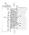
- the wedge ring pack 24 comprises two first, mirror-symmetrical Wedge rings 28 and a second wedge ring 30.
- the first two wedge rings 28 lie with their inner sides sealingly against the control shaft 14, while the second wedge ring 30 with its outside sealing against the cylindrical Housing wall 32 is present.
- the first two wedge rings 28 exist in the case of the described Embodiment from a suitable lubricious PTFE compound , that is to say of a material which is easy to slide, while the second wedge ring 30 consists of pure flowable PTFE, i.e. of a good flowable material.
- the inside of the second wedge ring 3o is roof-shaped with two inclined Wedge surfaces 34 formed, each wedge surface 34 with one on each Interacts outside of each wedge ring formed wedge surface 36.
- the two stand in the unsealed condition of the seal first wedge rings 28 in the axial direction via the second wedge ring 30 before, the wear occurring during operation by tightening the gland screw 20 can be compensated.
- the two wedge surfaces 34 of the second Wedge rings 30 are each followed by a deflection surface 38 which extends up to extends towards the button and is much more inclined than that Wedge surface 34.
- the two first wedge rings 28 have on their deflection surfaces facing ends on end surfaces 40, the inclination of the Inclination of the deflection surfaces corresponds. If by mission-related Wear, the two wedge rings 28 rest on the end of the wedge ring 30, so there is a so-called emergency seal. Adjusting the gland screw 20 causes the facing ends of the first Wedge rings 28 on the deflection surfaces 38 pressed against the selector shaft become and deform and thus cause an additional sealing function. At the same time, the static seal 30 is pressed in the opposite direction.
- the sealing reserve is in geometry of the two wedge rings 28 integrated and in Figure 3 by the dimension a illustrated.
- the first wedge rings 28 are on the side facing the selector shaft Grooves or grooves 42 are provided, likewise the one facing the housing wall
- the side of the second wedge ring 30 is provided with grooves or grooves 44.
- the remaining slats 46 and 48 result in those described above Benefits.
- the assembly grease used during assembly can accumulate in the grooves between the fins, creating a fat store is created, the continuous grease especially on the selector shaft delivers.
Landscapes
- Engineering & Computer Science (AREA)
- General Engineering & Computer Science (AREA)
- Mechanical Engineering (AREA)
- Taps Or Cocks (AREA)
- Sealing Devices (AREA)
- Lift Valve (AREA)
- Glass Compositions (AREA)
- Details Of Valves (AREA)
Applications Claiming Priority (2)
| Application Number | Priority Date | Filing Date | Title |
|---|---|---|---|
| DE20005319U | 2000-03-22 | ||
| DE20005319U DE20005319U1 (de) | 2000-03-22 | 2000-03-22 | Abdichtsystem für die Schaltwelle einer Armatur |
Publications (3)
| Publication Number | Publication Date |
|---|---|
| EP1136738A2 true EP1136738A2 (fr) | 2001-09-26 |
| EP1136738A3 EP1136738A3 (fr) | 2002-09-18 |
| EP1136738B1 EP1136738B1 (fr) | 2004-05-19 |
Family
ID=7939180
Family Applications (1)
| Application Number | Title | Priority Date | Filing Date |
|---|---|---|---|
| EP01105425A Expired - Lifetime EP1136738B1 (fr) | 2000-03-22 | 2001-03-13 | Joint d'étanchéité pour tige de vanne |
Country Status (3)
| Country | Link |
|---|---|
| EP (1) | EP1136738B1 (fr) |
| AT (1) | ATE267356T1 (fr) |
| DE (2) | DE20005319U1 (fr) |
Families Citing this family (2)
| Publication number | Priority date | Publication date | Assignee | Title |
|---|---|---|---|---|
| DE102007029620A1 (de) * | 2007-06-26 | 2009-01-08 | Richter Chemie- Technik Gmbh | Stopfbuchspackung |
| GB201116858D0 (en) * | 2011-09-30 | 2011-11-09 | Gt Group Ltd | Improved butterfly valve |
Family Cites Families (12)
| Publication number | Priority date | Publication date | Assignee | Title |
|---|---|---|---|---|
| DE1159233B (de) * | 1959-12-08 | 1963-12-12 | Linde S Eismaschinen Ag Zweign | Stopfbuechsenpackung in Ventilen fuer aggressive Gase, insbesondere Sauerstoff |
| FR1344415A (fr) * | 1962-10-16 | 1963-11-29 | Dispositif d'étanchéité notamment pour tige de commande de robinet | |
| US3608912A (en) * | 1969-11-04 | 1971-09-28 | Xomox Corp | Sealing means for valve stems |
| US4169604A (en) * | 1978-04-19 | 1979-10-02 | Heathcott Joe W | Rod seal |
| GB2103310B (en) * | 1981-07-31 | 1985-07-24 | Smith International | Seal |
| US4489916A (en) * | 1982-04-07 | 1984-12-25 | Cameron Iron Works, Inc. | Valve and stem seal therefor |
| DE3907103A1 (de) * | 1989-03-04 | 1990-09-13 | Argus Gmbh | Abgedichtete durchfuehrung einer welle durch eine lagerausnehmung |
| DE4110080C2 (de) * | 1991-03-27 | 1995-10-05 | Draxler Ernst Dipl Ing Fh | Titel: Kugelhahn I |
| US5205317A (en) * | 1991-09-12 | 1993-04-27 | Delta Industrial Valves, Inc. | Valve assembly |
| DE19627326C2 (de) * | 1996-06-26 | 2000-09-21 | Rautenkranz Int Hermann | Doppelte metallische Dichtungsanordnung für rotierende Wellen |
| EP0937925A1 (fr) * | 1998-02-19 | 1999-08-25 | James Wang | Joint d'étanchéité d'un robinet |
| US6273431B1 (en) * | 1999-11-15 | 2001-08-14 | Garlock Inc | Forged valve stem packing set |
-
2000
- 2000-03-22 DE DE20005319U patent/DE20005319U1/de not_active Expired - Lifetime
-
2001
- 2001-03-13 AT AT01105425T patent/ATE267356T1/de not_active IP Right Cessation
- 2001-03-13 EP EP01105425A patent/EP1136738B1/fr not_active Expired - Lifetime
- 2001-03-13 DE DE50102305T patent/DE50102305D1/de not_active Expired - Fee Related
Non-Patent Citations (1)
| Title |
|---|
| None |
Also Published As
| Publication number | Publication date |
|---|---|
| DE50102305D1 (de) | 2004-06-24 |
| EP1136738B1 (fr) | 2004-05-19 |
| EP1136738A3 (fr) | 2002-09-18 |
| ATE267356T1 (de) | 2004-06-15 |
| DE20005319U1 (de) | 2001-06-07 |
Similar Documents
| Publication | Publication Date | Title |
|---|---|---|
| AT392139B (de) | Dichtungsanordnung fuer einen rohrleitungsschalter | |
| DE69925631T2 (de) | Doppelte dichtungsanordnung | |
| DE69114454T2 (de) | Dichtung mit Druckfeder. | |
| EP2027403B1 (fr) | Structure d'étanchéite pour décompression | |
| DE3788433T2 (de) | Ventil. | |
| DE69117655T2 (de) | Spielfreie Stützringe für die Beschränkung von PTFE-Packungen | |
| DE3320515C1 (de) | Hochdruckdichtung fuer laengsverschieblich gegeneinander bewegbare Teile von Tiefbohrwerkzeugen | |
| DE2840323A1 (de) | Hochdruckventil und dichtung hierfuer | |
| DE2556900C2 (de) | Vorrichtung zum Dichten beweglicher Teile | |
| DE3228583C2 (fr) | ||
| DE3322582A1 (de) | Schieber | |
| DE3526699A1 (de) | Hochdruckfluiddichtung | |
| EP0724693B1 (fr) | Dispositif d'étanchéité | |
| EP4118365A1 (fr) | Ensemble segment de piston, compresseur à piston et procédé permettant de sceller une chambre de compression | |
| EP1136738B1 (fr) | Joint d'étanchéité pour tige de vanne | |
| WO2012022565A1 (fr) | Soupape à vide et élément de fermeture servant à fermer de manière étanche au gaz un trajet d'écoulement au moyen d'un mouvement linéaire | |
| DE1525427B1 (de) | Wellendichtung mit zwei Gleichringdichtungen | |
| DE60021750T2 (de) | Schraubenrotormaschine mit einer einrichtung, um zumindest auf einem rotor einen axialschub auszuüben | |
| DE3727173A1 (de) | Durch ein kompressibles fluid, insbesondere pneumatisch schaltbare kupplungs- und bremsvorrichtung | |
| EP1769176A1 (fr) | Ensemble d'etancheite | |
| EP2673471B1 (fr) | Élément d'étanchéité pour machine à piston rotatif | |
| DE19545172C2 (de) | Kompaktdichtung | |
| DE19734497C2 (de) | Dichtungsanordnung zur Abdichtung einer Kolbenstange | |
| CH704934A2 (de) | Vakuumventil-Balg. | |
| DE3437247C2 (de) | Dichtung, insbesondere für Laufwerksketten |
Legal Events
| Date | Code | Title | Description |
|---|---|---|---|
| PUAI | Public reference made under article 153(3) epc to a published international application that has entered the european phase |
Free format text: ORIGINAL CODE: 0009012 |
|
| AK | Designated contracting states |
Kind code of ref document: A2 Designated state(s): AT BE CH CY DE DK ES FI FR GB GR IE IT LI LU MC NL PT SE TR |
|
| AX | Request for extension of the european patent |
Free format text: AL;LT;LV;MK;RO;SI |
|
| PUAL | Search report despatched |
Free format text: ORIGINAL CODE: 0009013 |
|
| AK | Designated contracting states |
Kind code of ref document: A3 Designated state(s): AT BE CH CY DE DK ES FI FR GB GR IE IT LI LU MC NL PT SE TR |
|
| AX | Request for extension of the european patent |
Free format text: AL;LT;LV;MK;RO;SI |
|
| RIC1 | Information provided on ipc code assigned before grant |
Free format text: 7F 16K 41/02 A, 7F 16K 5/06 B, 7F 16K 41/04 B |
|
| 17P | Request for examination filed |
Effective date: 20030228 |
|
| AKX | Designation fees paid |
Designated state(s): AT BE CH CY DE DK ES FI FR GB GR IE IT LI LU MC NL PT SE TR |
|
| 17Q | First examination report despatched |
Effective date: 20030514 |
|
| GRAP | Despatch of communication of intention to grant a patent |
Free format text: ORIGINAL CODE: EPIDOSNIGR1 |
|
| GRAS | Grant fee paid |
Free format text: ORIGINAL CODE: EPIDOSNIGR3 |
|
| GRAA | (expected) grant |
Free format text: ORIGINAL CODE: 0009210 |
|
| AK | Designated contracting states |
Kind code of ref document: B1 Designated state(s): AT BE CH CY DE DK ES FI FR GB GR IE IT LI LU MC NL PT SE TR |
|
| PG25 | Lapsed in a contracting state [announced via postgrant information from national office to epo] |
Ref country code: TR Free format text: LAPSE BECAUSE OF FAILURE TO SUBMIT A TRANSLATION OF THE DESCRIPTION OR TO PAY THE FEE WITHIN THE PRESCRIBED TIME-LIMIT Effective date: 20040519 Ref country code: NL Free format text: LAPSE BECAUSE OF FAILURE TO SUBMIT A TRANSLATION OF THE DESCRIPTION OR TO PAY THE FEE WITHIN THE PRESCRIBED TIME-LIMIT Effective date: 20040519 Ref country code: IT Free format text: LAPSE BECAUSE OF FAILURE TO SUBMIT A TRANSLATION OF THE DESCRIPTION OR TO PAY THE FEE WITHIN THE PRESCRIBED TIME-LIMIT;WARNING: LAPSES OF ITALIAN PATENTS WITH EFFECTIVE DATE BEFORE 2007 MAY HAVE OCCURRED AT ANY TIME BEFORE 2007. THE CORRECT EFFECTIVE DATE MAY BE DIFFERENT FROM THE ONE RECORDED. Effective date: 20040519 Ref country code: GB Free format text: LAPSE BECAUSE OF FAILURE TO SUBMIT A TRANSLATION OF THE DESCRIPTION OR TO PAY THE FEE WITHIN THE PRESCRIBED TIME-LIMIT Effective date: 20040519 Ref country code: FR Free format text: LAPSE BECAUSE OF FAILURE TO SUBMIT A TRANSLATION OF THE DESCRIPTION OR TO PAY THE FEE WITHIN THE PRESCRIBED TIME-LIMIT Effective date: 20040519 Ref country code: FI Free format text: LAPSE BECAUSE OF FAILURE TO SUBMIT A TRANSLATION OF THE DESCRIPTION OR TO PAY THE FEE WITHIN THE PRESCRIBED TIME-LIMIT Effective date: 20040519 Ref country code: IE Free format text: LAPSE BECAUSE OF FAILURE TO SUBMIT A TRANSLATION OF THE DESCRIPTION OR TO PAY THE FEE WITHIN THE PRESCRIBED TIME-LIMIT Effective date: 20040519 |
|
| REG | Reference to a national code |
Ref country code: GB Ref legal event code: FG4D Free format text: NOT ENGLISH |
|
| REG | Reference to a national code |
Ref country code: CH Ref legal event code: EP |
|
| REG | Reference to a national code |
Ref country code: IE Ref legal event code: FG4D Free format text: GERMAN |
|
| REF | Corresponds to: |
Ref document number: 50102305 Country of ref document: DE Date of ref document: 20040624 Kind code of ref document: P |
|
| PG25 | Lapsed in a contracting state [announced via postgrant information from national office to epo] |
Ref country code: DK Free format text: LAPSE BECAUSE OF FAILURE TO SUBMIT A TRANSLATION OF THE DESCRIPTION OR TO PAY THE FEE WITHIN THE PRESCRIBED TIME-LIMIT Effective date: 20040819 Ref country code: GR Free format text: LAPSE BECAUSE OF FAILURE TO SUBMIT A TRANSLATION OF THE DESCRIPTION OR TO PAY THE FEE WITHIN THE PRESCRIBED TIME-LIMIT Effective date: 20040819 Ref country code: SE Free format text: LAPSE BECAUSE OF FAILURE TO SUBMIT A TRANSLATION OF THE DESCRIPTION OR TO PAY THE FEE WITHIN THE PRESCRIBED TIME-LIMIT Effective date: 20040819 |
|
| PG25 | Lapsed in a contracting state [announced via postgrant information from national office to epo] |
Ref country code: ES Free format text: LAPSE BECAUSE OF FAILURE TO SUBMIT A TRANSLATION OF THE DESCRIPTION OR TO PAY THE FEE WITHIN THE PRESCRIBED TIME-LIMIT Effective date: 20040830 |
|
| NLV1 | Nl: lapsed or annulled due to failure to fulfill the requirements of art. 29p and 29m of the patents act | ||
| GBV | Gb: ep patent (uk) treated as always having been void in accordance with gb section 77(7)/1977 [no translation filed] |
Effective date: 20040519 |
|
| REG | Reference to a national code |
Ref country code: IE Ref legal event code: FD4D |
|
| PG25 | Lapsed in a contracting state [announced via postgrant information from national office to epo] |
Ref country code: LU Free format text: LAPSE BECAUSE OF NON-PAYMENT OF DUE FEES Effective date: 20050313 Ref country code: CY Free format text: LAPSE BECAUSE OF FAILURE TO SUBMIT A TRANSLATION OF THE DESCRIPTION OR TO PAY THE FEE WITHIN THE PRESCRIBED TIME-LIMIT Effective date: 20050313 Ref country code: AT Free format text: LAPSE BECAUSE OF NON-PAYMENT OF DUE FEES Effective date: 20050313 |
|
| PLBE | No opposition filed within time limit |
Free format text: ORIGINAL CODE: 0009261 |
|
| STAA | Information on the status of an ep patent application or granted ep patent |
Free format text: STATUS: NO OPPOSITION FILED WITHIN TIME LIMIT |
|
| PG25 | Lapsed in a contracting state [announced via postgrant information from national office to epo] |
Ref country code: MC Free format text: LAPSE BECAUSE OF NON-PAYMENT OF DUE FEES Effective date: 20050331 Ref country code: LI Free format text: LAPSE BECAUSE OF NON-PAYMENT OF DUE FEES Effective date: 20050331 Ref country code: CH Free format text: LAPSE BECAUSE OF NON-PAYMENT OF DUE FEES Effective date: 20050331 Ref country code: BE Free format text: LAPSE BECAUSE OF NON-PAYMENT OF DUE FEES Effective date: 20050331 |
|
| 26N | No opposition filed |
Effective date: 20050222 |
|
| EN | Fr: translation not filed | ||
| BERE | Be: lapsed |
Owner name: S.A. *JC FABRICA DE VALVULAS Effective date: 20050331 |
|
| PG25 | Lapsed in a contracting state [announced via postgrant information from national office to epo] |
Ref country code: DE Free format text: LAPSE BECAUSE OF NON-PAYMENT OF DUE FEES Effective date: 20051001 |
|
| REG | Reference to a national code |
Ref country code: CH Ref legal event code: PL |
|
| BERE | Be: lapsed |
Owner name: S.A. *JC FABRICA DE VALVULAS Effective date: 20050331 |
|
| PG25 | Lapsed in a contracting state [announced via postgrant information from national office to epo] |
Ref country code: PT Free format text: LAPSE BECAUSE OF NON-PAYMENT OF DUE FEES Effective date: 20041019 |