EP1136744A1 - Elément d'amortissement - Google Patents
Elément d'amortissement Download PDFInfo
- Publication number
- EP1136744A1 EP1136744A1 EP00106423A EP00106423A EP1136744A1 EP 1136744 A1 EP1136744 A1 EP 1136744A1 EP 00106423 A EP00106423 A EP 00106423A EP 00106423 A EP00106423 A EP 00106423A EP 1136744 A1 EP1136744 A1 EP 1136744A1
- Authority
- EP
- European Patent Office
- Prior art keywords
- damping element
- fastening element
- opening
- damping
- elevations
- Prior art date
- Legal status (The legal status is an assumption and is not a legal conclusion. Google has not performed a legal analysis and makes no representation as to the accuracy of the status listed.)
- Withdrawn
Links
- 238000013016 damping Methods 0.000 title claims abstract description 95
- 230000010349 pulsation Effects 0.000 claims abstract description 9
- 239000007788 liquid Substances 0.000 claims abstract description 8
- 210000002445 nipple Anatomy 0.000 claims description 11
- 238000010276 construction Methods 0.000 claims description 3
- 239000000463 material Substances 0.000 description 3
- 239000011324 bead Substances 0.000 description 2
- 238000000034 method Methods 0.000 description 2
- 239000004033 plastic Substances 0.000 description 2
- 229920001343 polytetrafluoroethylene Polymers 0.000 description 2
- 239000004810 polytetrafluoroethylene Substances 0.000 description 2
- 238000005086 pumping Methods 0.000 description 2
- 230000003068 static effect Effects 0.000 description 2
- 238000005266 casting Methods 0.000 description 1
- 230000006735 deficit Effects 0.000 description 1
- 230000000694 effects Effects 0.000 description 1
- 239000013013 elastic material Substances 0.000 description 1
- 230000002708 enhancing effect Effects 0.000 description 1
- 230000005284 excitation Effects 0.000 description 1
- 239000000446 fuel Substances 0.000 description 1
- 238000002347 injection Methods 0.000 description 1
- 239000007924 injection Substances 0.000 description 1
- 238000003754 machining Methods 0.000 description 1
- 239000002184 metal Substances 0.000 description 1
- 238000012986 modification Methods 0.000 description 1
- 230000004048 modification Effects 0.000 description 1
- 230000010363 phase shift Effects 0.000 description 1
- -1 polytetrafluoroethylene Polymers 0.000 description 1
- 230000001902 propagating effect Effects 0.000 description 1
- 238000007493 shaping process Methods 0.000 description 1
- 230000007704 transition Effects 0.000 description 1
Images


Classifications
-
- F—MECHANICAL ENGINEERING; LIGHTING; HEATING; WEAPONS; BLASTING
- F16—ENGINEERING ELEMENTS AND UNITS; GENERAL MEASURES FOR PRODUCING AND MAINTAINING EFFECTIVE FUNCTIONING OF MACHINES OR INSTALLATIONS; THERMAL INSULATION IN GENERAL
- F16L—PIPES; JOINTS OR FITTINGS FOR PIPES; SUPPORTS FOR PIPES, CABLES OR PROTECTIVE TUBING; MEANS FOR THERMAL INSULATION IN GENERAL
- F16L55/00—Devices or appurtenances for use in, or in connection with, pipes or pipe systems
- F16L55/04—Devices damping pulsations or vibrations in fluids
Definitions
- the invention relates to a damping element for a conduit conducting a gaseous or liquid working medium through which pressure pulsations are applied.
- Damping elements also called tuners, of the type addressed here are known. They serve, inter alia, in hydraulic hoses for damping pulsations. These pulsations in hydraulic or pneumatic systems arise from the fact that the working medium is conveyed by pumps or pumping systems which introduce periodically recurring pressure fluctuations into the system. Examples of such pumps or pumping systems are vane pumps or radial piston pumps, but also diaphragm pumps, such as are used in the automobile industry in steering servo systems and brake systems, and as fuel injection pumps.
- the pulsations of the working medium cause the conduits, mostly hoses or pipes, conveying the medium to execute vibrations which, for their part, can incite the surrounding air to execute vibrations and lead to an undesired generation of noise in the system.
- damping elements are constructed as small hollow bodies through which flow can occur, for example, as tubular elements which are arranged inside the conduit conducting the working medium.
- these damping elements are held with the aid of fastening elements which have fastening nipples onto which the damping elements are fitted.
- this means that the full cross-section of the damping element is not available for the working medium to flow through, and this is associated with a pressure loss in the conduit and an increase in the temperature of the working medium. Both lead to a poor energy balance of the entire system. It is therefore an object of the invention to create a damping element of the type mentioned at the beginning which eliminates the disadvantages named here.
- a damping element having the features of the present invention can achieve the foregoing. It is distinguished in that it can be plugged into the fastening element which will anchor the damping element. Consequently, the full cross-sectional surface is available to be flowed through by the working medium flowing through the fastening element and through the damping element. Pressure losses and temperature increases are therefore virtually excluded.
- the inner surface of the opening of the fastening element has no contour, so that the connection between the fastening element and damping element comes about solely from the static friction between the two. It is particularly economical to realize this variant.
- the inner side of the opening of the fastening element, into which the damping element is plugged is provided with elevations and/or depressions which enhance the frictional grip between the fastening element and damping element. This ensures a very high functional reliability.
- an exemplary embodiment is preferred in which the elevations and/or depressions are arranged on the inner surface of the opening of the fastening element in an annular or spiral shape. This refinement ensures a stronger frictional grip between the fastening element and the damping element, thus enhancing the grip between the two elements.
- a further exemplary embodiment of the damping element is distinguished in that the push-in contour on the inner surface of the opening of the fastening element is provided with teeth (similar to the surface of a file or rasp) by means of which the damping element is securely held.
- Fig. 1 shows a known damping element in partial section.
- Fig. 2 shows a damping element according to the invention attached to a fastening element, in partial section.
- Fig. 3 shows a fastening element with elevations, formed in an annular fashion on the inner side of the opening for holding the damping element, in longitudinal section.
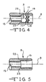
- Fig. 4 shows a fastening element with a push-in contour located on the inner side of the opening and comprising teeth, in longitudinal section.
- Fig. 5 shows a fastening element without a special push-in contour on the inner side of the opening, in longitudinal section.
- Fig. 6 is an elevational view, partly in section, of a preferred form of fastening element suitable for use with the damping element.
- Fig. 7 is an elevational view, partly in section, showing the damping element in combination with the fastening element of Fig. 6.
- Fig. 1 shows a damping element 1 which is attached in a conventional way to a fastening element 3.
- the fastening element 3 is provided with a fastening nipple 7 which proceeds from the basic body 5 of said element fastening element 3 and onto which the damping element 1 is pushed.
- Fig. 2 reproduces a damping element 1 and a fastening element 3. Identical parts are provided with identical reference numerals, to which extent reference is therefore made to the description based on Fig. 1.
- the damping element 1 is pushed into the fastening element 3 in the refinement reproduced in Fig. 2. This becomes plain, in particular, from the sectional representation below the center line 9.
- the interior of the damping element 1 remains completely free. Impairment of the flow behavior of the gaseous or liquid working medium in the region of the transition from the damping element 1 to the fastening element 3 does not occur here.
- the above described disadvantages of pressure reduction and increase in temperature in the region of the damping element 1 as attached to the fastening element 3 are avoided here virtually completely.
- the fastening element 3 reproduced in Fig. 2 is of hollow construction, for example, essentially tubular. Enlargement of the inside diameter is provided in the fastening region, thus producing an opening 13 for holding the damping element 1. Said opening 13 is distinguished by a larger inside diameter than that in the remaining region of the fastening element 3. It is realized, for example, by virtue of the fact that the fastening element 3 is bored in the holding region of the damping element 1. The widening of the diameter can also be achieved by any desired material-removing machining method, for example, by turning or the like. Finally, it is also conceivable when producing the fastening element 3 not only to provide the through channel 15, but also to produce the opening 13.
- the through channel 15 and the opening 13 can be produced using a shaping method. It is also conceivable to produce the fastening element from a sintered material and in so doing, to produce the through channel 15 and opening 13. Finally, this is also conceivable in the case of a casting operation of a fastening element 3 consisting of metal.
- the fastening element is provided with two elevations or annular beads 17 and 19 projecting above the inner surface of the opening 13 in the direction of the center line 9 which engage in the outer surface of the damping element 1, in the wall 11 thereof.
- the wall 11 is pressed in by the elevations 17 and 19 because of its inherent elasticity, with the result that the damping element 1 is held securely in the fastening element 3. If the wall 11 consists of a material which does not have such an elasticity, with the result that the elevations 17 and 19 cannot press in there, it is possible to provide depressions in the other surface of the wall 11 so that the elevations 17 and 19 are securely held there and retain the damping element 1.
- the inner surface in the region of the opening 13 can also be provided with depressions into which the wall 11 of the damping element 1 projects.
- the wall 11 from an elastic material which is compressed in the region of the opening 13 and which expands in the region of the depressions of the inner surface of the opening 13 and is virtually interlocking there. It is possible to provide defined elevations on the outer surface of the damping element 1 at least in the plug-in region of the opening 13, which then project into depressions on the inner surface of the opening 13.
- the damping element 1 is produced from a flexible material, preferably plastic, in particular polytetrafluoroethylene (PTFE). Because the damping element 1 is flexible, it can adapt to the shape to which it is constrained to adopt by the annular beads 17 and 19 of fastening element 3 to which it is attached and the hose for conducting the liquid or gaseous medium.
- PTFE polytetrafluoroethylene
- the wall 11 of the damping element 1 is provided with a series of apertures 24.
- the elevations 17 and 19 and the depressions in the damping element 1 in which the elevations engage can form rings arranged at a spacing from one another. Seen in the circumferential direction, the elevations 17 and 19 are then constructed continuously and, as previously discussed, form depressions on the outer side in the wall 11 of the damping element 1. Instead of a plurality of parallel rings comprising elevations 17 and 19, a single elevation is also conceivable which extends around on the inner surface of the opening 13 of the fastening element 3 in the shape of a spiral.
- step 23 runs essentially perpendicular to the center line 9 in order to ensure a defined stop.
- elevations 17 and 19 such that, seen in the circumferential direction, they comprise a plurality of groups of individual elevations which are arranged on an imaginary helix or on imaginary circular lines which possibly also run parallel to one another, as is also indicated in Fig. 4.
- the inner surface of the opening 13 then resembles the surface of a file or rasp.
- Such individual elevations can sink in particularly effectively into the outer surface of the damping element 1 and anchor the latter reliably on the fastening element 3.
- the opening 13 can be provided in the plug-in region of the damping element 1 with a smooth inner surface whose inside diameter is matched to the outside diameter of the damping element 1 such that the latter is held firmly in the opening 13 and, by virtue of static friction, cannot inadvertently slip out of the fastening element 3.
- the wall 11 of the damping element 1 has juxtaposed spirals which lie closely next to one another. However, it is possible for the medium flowing through the damping element 1 to emerge through the interspace between neighboring spirals in the event of pulsations by flowing through apertures 24 in the wall 11.
- the pressure wave running through the hydraulic medium is damped by the damping element 1 in two different ways: in the ideal case (of interest only given constant excitation), the pressure wave propagating in the liquid or gaseous medium has a wavelength ⁇ . If the damping element 1 has a length which corresponds precisely to a quarter of this wavelength ⁇ , a pressure wave which runs back on the outside of the damping element 1 against the direction of flow and is reflected at the end has a phase shift of half a wavelength upon encountering the next pressure wave at the outlet end of the damping element 1. The pressure wave is thus completely damped after running through the damping element, that is to say nothing more is left of the pressure wave in this ideal case. In practice, this ideal case can be realized only given a constant pump speed.
- the pressure wave mostly contains various wavelengths components, for which reason only a part of the pressure wave is damped by the damping element 1.
- the openings 24 introduced into the wall 11 of the damping elements 1. Specifically, if the hydraulic medium passes through these openings 24, eddies are produced which partially reflect and additionally damp the pressure wave running through the fastening element 3 and the damping element 1. In the case of the damping elements constructed as spirals, this type of damping can be realized by virtue of the fact that the medium emerges between the spirals.
- a nipple or fastening element 30 having an opening 33 and a through channel 35.
- the nipple or fastening element 30 is provided with a plurality of circumferentially extending teeth 36 for engaging and retaining the internal surface of a hose connected thereto.
- the interior surface defining the opening 33 is provided with circumferentially extending teeth 38 for engaging the outer wall 41 of the damping element 40.
- the teeth 38 are defined by wall sections 32 which taper inwardly toward the center line 9 at an angle of approximately 5° relative to the center line 9 in a direction extending away from the receiving end 37 of the nipple or fastening element 30.
- Each tapering wall segment 32 terminates in a shoulder 34 having a sharp edge which deforms the outer wall 41 of the damping element 40 thereby retaining the damping element 40 on the nipple or fastening element 33.
- the damping element 40 could also be provided with apertures extending outwardly therethrough to the outer wall 41 similar to the apertures 24 of the embodiment of Fig. 2.
- the description of the present invention has shown that it is possible to provide on the fastening element and on the damping element means such as elevations and/or depressions which enhance the frictional grip and/or self-closure between the fastening element and damping element.
- the advantage described results in both cases, specifically reliable holding between the fastening element and damping element.
Landscapes
- Engineering & Computer Science (AREA)
- General Engineering & Computer Science (AREA)
- Mechanical Engineering (AREA)
- Pipe Accessories (AREA)
- Vibration Prevention Devices (AREA)
- Mutual Connection Of Rods And Tubes (AREA)
Priority Applications (2)
| Application Number | Priority Date | Filing Date | Title |
|---|---|---|---|
| CA002302566A CA2302566C (fr) | 2000-03-22 | 2000-03-22 | Element amortisseur |
| EP00106423A EP1136744A1 (fr) | 2000-03-22 | 2000-03-24 | Elément d'amortissement |
Applications Claiming Priority (2)
| Application Number | Priority Date | Filing Date | Title |
|---|---|---|---|
| CA002302566A CA2302566C (fr) | 2000-03-22 | 2000-03-22 | Element amortisseur |
| EP00106423A EP1136744A1 (fr) | 2000-03-22 | 2000-03-24 | Elément d'amortissement |
Publications (1)
| Publication Number | Publication Date |
|---|---|
| EP1136744A1 true EP1136744A1 (fr) | 2001-09-26 |
Family
ID=25681668
Family Applications (1)
| Application Number | Title | Priority Date | Filing Date |
|---|---|---|---|
| EP00106423A Withdrawn EP1136744A1 (fr) | 2000-03-22 | 2000-03-24 | Elément d'amortissement |
Country Status (2)
| Country | Link |
|---|---|
| EP (1) | EP1136744A1 (fr) |
| CA (1) | CA2302566C (fr) |
Cited By (2)
| Publication number | Priority date | Publication date | Assignee | Title |
|---|---|---|---|---|
| WO2005095875A1 (fr) * | 2004-03-30 | 2005-10-13 | Mitsubishi Denki Kabushiki Kaisha | Dispositif de circuit d’ecoulement, dispositif de cycle de congelation, dispositif de reduction de pulsation de pression, et procede de reduction de pulsation de pression |
| FR2999990A1 (fr) * | 2012-12-20 | 2014-06-27 | Peugeot Citroen Automobiles Sa | Moteur hybride pneumatique-thermique |
Citations (5)
| Publication number | Priority date | Publication date | Assignee | Title |
|---|---|---|---|---|
| DE3510267A1 (de) * | 1984-03-23 | 1985-10-03 | Toyota Jidosha K.K., Toyota, Aichi | Zuleitungsschlauchsatz zur daempfung von fluiddruckpulsationen |
| US5094271A (en) * | 1989-07-05 | 1992-03-10 | Aeroquip Gmbh | Expandable hose that reduces the hammering produced in hydraulic system by pumps |
| EP0565183A1 (fr) * | 1992-04-06 | 1993-10-13 | Johan Gerrit Wormmeester | Amortisseur de coup de belier |
| US5728981A (en) * | 1994-12-12 | 1998-03-17 | Dayco Products, Inc. | Power steering attenuation hose construction and method of making the same |
| DE29823962U1 (de) * | 1998-11-13 | 2000-01-13 | Aeroquip-Vickers International GmbH, 76532 Baden-Baden | Dämpfungselement |
-
2000
- 2000-03-22 CA CA002302566A patent/CA2302566C/fr not_active Expired - Fee Related
- 2000-03-24 EP EP00106423A patent/EP1136744A1/fr not_active Withdrawn
Patent Citations (5)
| Publication number | Priority date | Publication date | Assignee | Title |
|---|---|---|---|---|
| DE3510267A1 (de) * | 1984-03-23 | 1985-10-03 | Toyota Jidosha K.K., Toyota, Aichi | Zuleitungsschlauchsatz zur daempfung von fluiddruckpulsationen |
| US5094271A (en) * | 1989-07-05 | 1992-03-10 | Aeroquip Gmbh | Expandable hose that reduces the hammering produced in hydraulic system by pumps |
| EP0565183A1 (fr) * | 1992-04-06 | 1993-10-13 | Johan Gerrit Wormmeester | Amortisseur de coup de belier |
| US5728981A (en) * | 1994-12-12 | 1998-03-17 | Dayco Products, Inc. | Power steering attenuation hose construction and method of making the same |
| DE29823962U1 (de) * | 1998-11-13 | 2000-01-13 | Aeroquip-Vickers International GmbH, 76532 Baden-Baden | Dämpfungselement |
Cited By (2)
| Publication number | Priority date | Publication date | Assignee | Title |
|---|---|---|---|---|
| WO2005095875A1 (fr) * | 2004-03-30 | 2005-10-13 | Mitsubishi Denki Kabushiki Kaisha | Dispositif de circuit d’ecoulement, dispositif de cycle de congelation, dispositif de reduction de pulsation de pression, et procede de reduction de pulsation de pression |
| FR2999990A1 (fr) * | 2012-12-20 | 2014-06-27 | Peugeot Citroen Automobiles Sa | Moteur hybride pneumatique-thermique |
Also Published As
| Publication number | Publication date |
|---|---|
| CA2302566A1 (fr) | 2001-09-22 |
| CA2302566C (fr) | 2005-08-16 |
Similar Documents
| Publication | Publication Date | Title |
|---|---|---|
| KR0180505B1 (ko) | 압력 맥동을 감소시키기 위한 팽창호스 | |
| US9476529B2 (en) | Hose nipple and hose arrangement | |
| US5470113A (en) | Connector for plastic tubes | |
| US4611633A (en) | Expansion hose for reduction of pressure pulsations | |
| EP0368850B1 (fr) | Raccord souple pour tuyaux | |
| FI110448B (fi) | Laite putkien pysyväksi yhteenliittämiseksi | |
| US7025390B2 (en) | Method and apparatus for connecting coupler fittings to conduit sections | |
| CN101371096A (zh) | 设有连接件的热交换器 | |
| US7434847B2 (en) | Quick connect tube coupling | |
| US6158472A (en) | Apparatus for damping a pulsation of a fluid conveyed through a conveying device | |
| US6244299B1 (en) | Damping element | |
| US20030057699A1 (en) | Coupling assembly with rotation lock | |
| CA2302566C (fr) | Element amortisseur | |
| AU777897B2 (en) | Damping element | |
| US7717135B2 (en) | Energy attenuation device | |
| US20040250865A1 (en) | Tuning cable | |
| US20080036207A1 (en) | Connector of Flexible Pipe | |
| US3908788A (en) | Silencer and flow regulator particularly for water conduits | |
| KR101942610B1 (ko) | 특히 유체 라인, 피팅 또는 어셈블리를 위한 플러그인 연결 장치 | |
| JPS616494A (ja) | 脈動吸収ホ−ス | |
| US7373824B2 (en) | Automotive automatic transmission noise attenuators | |
| EP0940617A3 (fr) | Système d'accouplement rapide | |
| US7347222B2 (en) | Energy attenuation device | |
| KR100546755B1 (ko) | 감쇠 요소 | |
| JPH10306889A (ja) | 配管継手 |
Legal Events
| Date | Code | Title | Description |
|---|---|---|---|
| PUAI | Public reference made under article 153(3) epc to a published international application that has entered the european phase |
Free format text: ORIGINAL CODE: 0009012 |
|
| AK | Designated contracting states |
Kind code of ref document: A1 Designated state(s): AT BE CH CY DE DK ES FI FR GB GR IE IT LI LU MC NL PT SE Kind code of ref document: A1 Designated state(s): DE ES FR GB IT |
|
| AX | Request for extension of the european patent |
Free format text: AL;LT;LV;MK;RO;SI |
|
| 17P | Request for examination filed |
Effective date: 20020321 |
|
| AKX | Designation fees paid |
Free format text: DE ES FR GB IT |
|
| 17Q | First examination report despatched |
Effective date: 20030514 |
|
| STAA | Information on the status of an ep patent application or granted ep patent |
Free format text: STATUS: THE APPLICATION IS DEEMED TO BE WITHDRAWN |
|
| 18D | Application deemed to be withdrawn |
Effective date: 20030925 |