EP1136764A2 - Heat exchanger for gas fired condensing boiler - Google Patents
Heat exchanger for gas fired condensing boiler Download PDFInfo
- Publication number
- EP1136764A2 EP1136764A2 EP01104013A EP01104013A EP1136764A2 EP 1136764 A2 EP1136764 A2 EP 1136764A2 EP 01104013 A EP01104013 A EP 01104013A EP 01104013 A EP01104013 A EP 01104013A EP 1136764 A2 EP1136764 A2 EP 1136764A2
- Authority
- EP
- European Patent Office
- Prior art keywords
- heat exchanger
- knobs
- flue gas
- flow direction
- section
- Prior art date
- Legal status (The legal status is an assumption and is not a legal conclusion. Google has not performed a legal analysis and makes no representation as to the accuracy of the status listed.)
- Granted
Links
- UGFAIRIUMAVXCW-UHFFFAOYSA-N Carbon monoxide Chemical compound [O+]#[C-] UGFAIRIUMAVXCW-UHFFFAOYSA-N 0.000 claims abstract description 39
- 239000003546 flue gas Substances 0.000 claims abstract description 39
- 238000004140 cleaning Methods 0.000 claims abstract description 11
- 238000007689 inspection Methods 0.000 claims abstract description 10
- 239000007789 gas Substances 0.000 claims abstract description 5
- 229910052782 aluminium Inorganic materials 0.000 claims description 4
- XAGFODPZIPBFFR-UHFFFAOYSA-N aluminium Chemical compound [Al] XAGFODPZIPBFFR-UHFFFAOYSA-N 0.000 claims description 4
- 238000005058 metal casting Methods 0.000 claims description 3
- 238000005266 casting Methods 0.000 claims description 2
- 230000015572 biosynthetic process Effects 0.000 abstract description 4
- 238000002485 combustion reaction Methods 0.000 description 3
- 238000005260 corrosion Methods 0.000 description 3
- 230000007797 corrosion Effects 0.000 description 3
- XLYOFNOQVPJJNP-UHFFFAOYSA-N water Substances O XLYOFNOQVPJJNP-UHFFFAOYSA-N 0.000 description 3
- 238000000034 method Methods 0.000 description 2
- 239000002245 particle Substances 0.000 description 2
- 230000002378 acidificating effect Effects 0.000 description 1
- 229910045601 alloy Inorganic materials 0.000 description 1
- 239000000956 alloy Substances 0.000 description 1
- CSDREXVUYHZDNP-UHFFFAOYSA-N alumanylidynesilicon Chemical compound [Al].[Si] CSDREXVUYHZDNP-UHFFFAOYSA-N 0.000 description 1
- 238000004519 manufacturing process Methods 0.000 description 1
- 239000000463 material Substances 0.000 description 1
- 229910052751 metal Inorganic materials 0.000 description 1
- 239000002184 metal Substances 0.000 description 1
- 239000000843 powder Substances 0.000 description 1
- 238000007528 sand casting Methods 0.000 description 1
- 239000000779 smoke Substances 0.000 description 1
- 239000007858 starting material Substances 0.000 description 1
Images


Classifications
-
- F—MECHANICAL ENGINEERING; LIGHTING; HEATING; WEAPONS; BLASTING
- F24—HEATING; RANGES; VENTILATING
- F24H—FLUID HEATERS, e.g. WATER OR AIR HEATERS, HAVING HEAT-GENERATING MEANS, e.g. HEAT PUMPS, IN GENERAL
- F24H9/00—Details
- F24H9/0005—Details for water heaters
- F24H9/001—Guiding means
- F24H9/0026—Guiding means in combustion gas channels
-
- F—MECHANICAL ENGINEERING; LIGHTING; HEATING; WEAPONS; BLASTING
- F24—HEATING; RANGES; VENTILATING
- F24H—FLUID HEATERS, e.g. WATER OR AIR HEATERS, HAVING HEAT-GENERATING MEANS, e.g. HEAT PUMPS, IN GENERAL
- F24H1/00—Water heaters, e.g. boilers, continuous-flow heaters or water-storage heaters
- F24H1/22—Water heaters other than continuous-flow or water-storage heaters, e.g. water heaters for central heating
- F24H1/24—Water heaters other than continuous-flow or water-storage heaters, e.g. water heaters for central heating with water mantle surrounding the combustion chamber or chambers
-
- F—MECHANICAL ENGINEERING; LIGHTING; HEATING; WEAPONS; BLASTING
- F24—HEATING; RANGES; VENTILATING
- F24H—FLUID HEATERS, e.g. WATER OR AIR HEATERS, HAVING HEAT-GENERATING MEANS, e.g. HEAT PUMPS, IN GENERAL
- F24H8/00—Fluid heaters characterised by means for extracting latent heat from flue gases by means of condensation
-
- F—MECHANICAL ENGINEERING; LIGHTING; HEATING; WEAPONS; BLASTING
- F24—HEATING; RANGES; VENTILATING
- F24H—FLUID HEATERS, e.g. WATER OR AIR HEATERS, HAVING HEAT-GENERATING MEANS, e.g. HEAT PUMPS, IN GENERAL
- F24H9/00—Details
- F24H9/0005—Details for water heaters
- F24H9/0042—Cleaning arrangements
-
- F—MECHANICAL ENGINEERING; LIGHTING; HEATING; WEAPONS; BLASTING
- F28—HEAT EXCHANGE IN GENERAL
- F28F—DETAILS OF HEAT-EXCHANGE AND HEAT-TRANSFER APPARATUS, OF GENERAL APPLICATION
- F28F3/00—Plate-like or laminated elements; Assemblies of plate-like or laminated elements
- F28F3/02—Elements or assemblies thereof with means for increasing heat-transfer area, e.g. with fins, with recesses, with corrugations
- F28F3/022—Elements or assemblies thereof with means for increasing heat-transfer area, e.g. with fins, with recesses, with corrugations the means being wires or pins
-
- Y—GENERAL TAGGING OF NEW TECHNOLOGICAL DEVELOPMENTS; GENERAL TAGGING OF CROSS-SECTIONAL TECHNOLOGIES SPANNING OVER SEVERAL SECTIONS OF THE IPC; TECHNICAL SUBJECTS COVERED BY FORMER USPC CROSS-REFERENCE ART COLLECTIONS [XRACs] AND DIGESTS
- Y02—TECHNOLOGIES OR APPLICATIONS FOR MITIGATION OR ADAPTATION AGAINST CLIMATE CHANGE
- Y02B—CLIMATE CHANGE MITIGATION TECHNOLOGIES RELATED TO BUILDINGS, e.g. HOUSING, HOUSE APPLIANCES OR RELATED END-USER APPLICATIONS
- Y02B30/00—Energy efficient heating, ventilation or air conditioning [HVAC]
Definitions
- the invention relates to a heat exchanger for a gas condensing boiler at least one flue gas duct, that of water-cooled heat exchanger walls surrounded with surface structure and for cleaning via an inspection opening is accessible.
- Such heat exchangers are often manufactured using the metal casting process, where aluminum castings are used, the sand casting process are manufactured. So in the smallest of spaces and with the least amount of material an effective heat transfer between the flue gas and the heat exchanger flowing water is obtained, they are the flue gas duct enclosing heat exchanger walls with a surface enlarging Provided surface structure of ribs, knobs and the like. So that will achieved that the residual heat of the flue gas is largely used. This leads to the formation of condensate on the heat exchanger walls, however become acidic due to the flue gas components and cause corrosion attack Heat exchanger walls can lead.
- One embodiment provides for the formation of cleaning channels of sufficient width before that the rows of knobs in the flow direction of the flue gas have a distance which is approximately the dimension of the knobs in the flow direction corresponds.
- a further embodiment provides that the knobs each other opposite heat exchanger walls are aligned and approximately in the mill between the heat exchanger walls at a distance from each other ends, and that the distance of the knobs in the flow direction is adjacent Rows alternating between the middle between the heat exchanger walls is offset. This makes the entire flue gas duct optimal for exploited the surface enlargement and turbulence.
- a further training is advantageous, which is characterized in that the knobs facing the inflow side of the flue gas duct in cross section run out in a circular arc or roof shape, and that the knobs on the outflow side of the flue gas duct turned almost perpendicular to the cross section Flow direction end. This brings an improved flow and a good condensate drain.
- the knobs in the rows can also have different cross sections. The same applies to the knobs of different rows. It recommends However, there is a configuration that is characterized in that at least the aligned pairs of the knobs facing each other Heat exchanger walls have the same cross section.
- the heat exchanger 20 according to FIGS. 1 to 3 is produced as a cast metal block, aluminum being used as the starting material.
- the top Area form part of the combustion chamber 17 or with a separate one Combustion chamber part to be connected.
- the flue gas flows in from the combustion chamber a flue gas duct as the flue gas 15 flowing into the heat exchanger 20.
- the flue gas duct is surrounded by heat exchanger walls 11 and 12 are cooled by water channels.
- the heat of the flue gas is above that Transfer heat exchanger 20 to the water.
- the cooled flue gas appears as outflowing flue gas 16 at the flue gas outlet 18 from the heat exchanger 20 out.
- FIG. 3 To enlarge the surface of the heat exchanger walls surrounding the flue gas duct 11 and 12 rows 13 of knobs 14 are formed, as Fig. 3 clearly shows.
- the rows 13 run transversely to the flow direction 25 of the Flue gas.
- the rows 13 are each offset with their knobs 14, as Fig. 3 shows.
- the knobs 14 are spaced apart and stick out in the form of a rod molded onto the heat exchanger walls 11 and 12. The smoke gases will diverted from row to row 13, so that there is turbulence throughout the flue gas duct form the heat exchange from flue gas to water in the heat exchanger 20 improve.
- the same There is also a distance between the knobs 14 in the rows.
- the knobs 14 have on the side facing the inflow side of the flue gas Initial section 14.1 with a continuously increasing cross section and can be circular or roof-shaped, like the 5 shows various cross sections of the knobs 14.
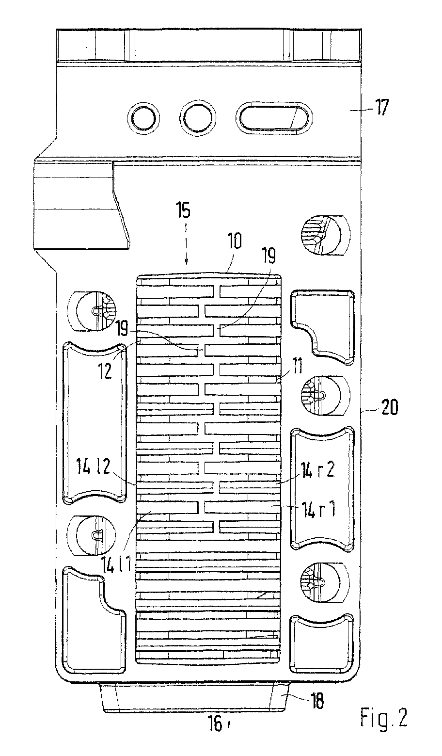
- FIG. 1 and 2 show are on the opposing heat exchanger walls 11 and 12 the knobs as right knobs 14r1 and 14r2 and left knobs 1411 and 1412 are aligned and extend approximately to the middle of the Flue gas duct, as Fig. 2 shows. However, they end at a distance 19 from one another. This distance 19 is from row to row of the knobs in relation to the Middle level offset on alternating sides.
- Rows of knobs 14 are preferably the cross sections of the pair of knobs equal. However, over the entire heat exchanger walls 11 and 12 Rows of pairs of knobs have different cross sections.
- the resulting condensate runs off the knobs 14 well and passes through the Flue gas outlet 18 to a condensate trap of the gas condensing boiler. The same also applies to that of the knobs 14 when cleaning the heat exchanger 20 removed particles.
Landscapes
- Engineering & Computer Science (AREA)
- Physics & Mathematics (AREA)
- Thermal Sciences (AREA)
- Mechanical Engineering (AREA)
- General Engineering & Computer Science (AREA)
- Chemical & Material Sciences (AREA)
- Combustion & Propulsion (AREA)
- Heat-Exchange Devices With Radiators And Conduit Assemblies (AREA)
Abstract
Die Erfindung betrifft einen Wärmetauscher für ein Gasbrennwertgerät mit
mindestens einem Rauchgaskanal, der von wassergekühlten Wärmetauscherwänden
mit Oberflächenstruktur umgeben und zur Reingigung über eine Inspektionsöffnung
zugänglich ist. Zur Vergrößerung der Oberflächenstruktur und
zur einfachen Inspektion und Reinigung des Wärmeübertrages ist nach der
Erfindung vorgesehen, dass die Oberflächenstruktur aus quer zur Strömungsrichtung
des Rauchgases gerichteten Reihen von stabförmigen, an den Wärmetauscherwänden
abstehenden angeformten Noppen besteht, und dass die Noppen
in Strömungsrichtung benachbarte Reihen jeweils auf Lücke angeordnet sind
und in dieser Strömungsrichtung zumindest einen Anfangsabschnitt mit kontinuierlich
zunehmendem Querschnitt aufweisen. Mit dieser Anordnung und Form
der Noppen wird gleichzeitig der Ablauf des Kondensates und die Turbulenzbildung
im Rauchgaskanal verbessert.
Description
Die Erfindung betrifft einen Wärmetauscher für ein Gasbrennwertgerät mit mindestens einem Rauchgaskanal, der von wassergekühlten Wärmetauscherwänden mit Oberflächenstruktur umgeben und zur Reinigung über eine Inspektionsöffnung zugänglich ist.The invention relates to a heat exchanger for a gas condensing boiler at least one flue gas duct, that of water-cooled heat exchanger walls surrounded with surface structure and for cleaning via an inspection opening is accessible.
Derartige Wärmetauscher werden heute vielfach im Metallgußverfahren hergestellt, wobei Aluminium-Gußteile verwendet sind, die im Sandgußverfahren hergestellt sind. Damit auf kleinstem Raum und mit geringstem Materialaufwand eine effektive Wärmeübertragung zwischen dem Rauchgas und dem, den Wärmetauscher durchfließenden Wasser erhalten wird, sind die den Rauchgaskanal umschließenden Wärmetauscherwände mit einer die Oberfläche vergrößernden Oberflächenstruktur aus Rippen, Noppen und dergleichen versehen. Damit wird erreicht, dass die Restwärme des Rauchgases weitgehend genutzt wird. Dies führt allerdings zur Bildung von Kondensat an den Wärmetauscherwänden, das aufgrund der Rauchgasbestandteile sauer werden und zum Korrosionsangriff der Wärmetauscherwände führen kann. Werden relativ korrosionsfeste Aluminium-Silizium-Gußlegierungen bei der Herstellung des Wärmetauschers verwendet, dann kann es dennoch innerhalb der Lebensdauer des Wärmetauschers zum Ausfall desselben kommen. Ursache dafür kann das Zusetzen der Spalte der Oberflächenstruktur durch die stark ausblühenden Korrosionsprodukte des Aluminiums sein.Such heat exchangers are often manufactured using the metal casting process, where aluminum castings are used, the sand casting process are manufactured. So in the smallest of spaces and with the least amount of material an effective heat transfer between the flue gas and the heat exchanger flowing water is obtained, they are the flue gas duct enclosing heat exchanger walls with a surface enlarging Provided surface structure of ribs, knobs and the like. So that will achieved that the residual heat of the flue gas is largely used. This leads to the formation of condensate on the heat exchanger walls, however become acidic due to the flue gas components and cause corrosion attack Heat exchanger walls can lead. Are relatively corrosion-resistant aluminum-silicon cast alloys used in the manufacture of the heat exchanger, then it can still within the life of the heat exchanger Failure of the same come. The reason for this can be the clogging of the column Surface structure due to the strongly blooming corrosion products of the Aluminum.
Es ist Aufgabe der Erfindung, einen Wärmetauscher der eingangs erwähnten Art mit einer Oberflächenstruktur auf den Wärmetauscherwänden im Bereich des Rauchgaskanals zu versehen, die eine optimale Wärmeübertragung auf kleinstem Raum ermöglicht, aber eine einfache Reinigung und einen guten Ablauf des entstehenden Kondensats ermöglicht.It is an object of the invention to provide a heat exchanger of the type mentioned with a surface structure on the heat exchanger walls in the area of the To provide flue gas duct, which optimal heat transfer on the smallest Allows space, but easy cleaning and good drainage of the condensate.
Diese Aufgabe wird nach der Erfindung dadurch gelöst, dass die Oberflächenstruktur aus quer zur Strömungsrichtung des Rauchgases gerichteten Reihen von stabförmigen, an den Wärmetauscherwänden abstehend angeformten Noppen besteht, und dass die Noppen in Strömungsrichtung benachbarter Reihen jeweils auf Lücke angeordnet sind und in dieser Strömungsrichtung zumindest einen Anfangsabschnitt mit kontinuierlich zunehmendem Querschnitt aufweisen.This object is achieved according to the invention in that the surface structure from rows directed transversely to the direction of flow of the flue gas Rod-shaped knobs protruding from the heat exchanger walls exists, and that the knobs in the flow direction of adjacent rows each are arranged on gap and at least one in this flow direction Have initial section with continuously increasing cross-section.
Bei dieser Ausgestaltung der Oberflächenstruktur entstehen zwischen den Reihen von Noppen Reinigungskanäle, die mit mechanischen Mitteln, z.B. einer speziellen Bürste oder geeigneten Werkzeugen gereinigt werden können, da sie nach dem Öffnen der Inspektionsöffnung zugänglich sind. Durch den abwechselnden Versatz der Noppen in aufeinander folgenden Reihen und ihrer Kontur werden Turbulenzen in der Rauchgasströmung erzeugt, die den Wärmeübergang verbessern. Der Querschnitt der Noppen begünstigt den Ablauf entstehenden Kondensats und den Wärmeübergang innerhalb der Noppen. Das Kondensat fließt in eine Kondensatauffangeinrichtung, die bei der Reinigung des Wärmetauschers auch die pulverförmigen Partikel aufnimmt, die von den Noppen und den Wärmetauscherwänden entfernt werden.With this configuration of the surface structure arise between the Rows of studs cleaning channels that are mechanically, e.g. one special brush or suitable tools can be cleaned as they accessible after opening the inspection opening. Due to the alternating Offset of the knobs in successive rows and their contours turbulence is generated in the flue gas flow, which affects the heat transfer improve. The cross-section of the knobs favors the run-off Condensate and heat transfer within the knobs. The condensate flows into a condensate trap, which is used to clean the Heat exchanger also picks up the powder particles from the nubs and the heat exchanger walls are removed.
Zur Bildung von Reinigungskanälen ausreichender Breite sieht eine Ausgestaltung vor, dass die Reihen von Noppen in Strömungsrichtung des Rauchgases einen Abstand aufweisen, der etwa der Abmessung der Noppen in Strömungsrichtung entspricht.One embodiment provides for the formation of cleaning channels of sufficient width before that the rows of knobs in the flow direction of the flue gas have a distance which is approximately the dimension of the knobs in the flow direction corresponds.
Um die Wärmeübertraung und die Bildung von Turbulenzen im Rauchgaskanal zu verbessern, sieht eine weitere Ausgestaltung vor, dass die Noppen einander gegenüberliegender Wärmetauscherwände aufeinander ausgerichtet sind und etwa in der Mltte zwischen den Wärmetauscherwänden in einem Abstand zueinander enden, sowie dass der Abstand der Noppen in Strömungrichtung benachbarter Reihen abwechselnd gegeüber der Mitte zwischen den Wärmetauscherwänden versetzt ist. Damit wird der gesamte Rauchgaskanal optimal für die Oberflächenvergrößerung und Turbulenzbildung ausgenützt.To the heat transfer and the formation of turbulence in the flue gas duct too improve, a further embodiment provides that the knobs each other opposite heat exchanger walls are aligned and approximately in the mill between the heat exchanger walls at a distance from each other ends, and that the distance of the knobs in the flow direction is adjacent Rows alternating between the middle between the heat exchanger walls is offset. This makes the entire flue gas duct optimal for exploited the surface enlargement and turbulence.
Dabei ist eine Weiterbildung von Vorteil, die dadurch gekennzeichnet ist, dass die Noppen der Einströmseite des Rauchgaskanals zugekehrt im Querschnitt kreisbogenförmig oder dachförmig auslaufen, sowie dass die Noppen der Ausströmseite des Rauchgaskanals zugekehrt im Querschnitt nahezu senkrecht zur Strömungsrichtung enden. Dies bringt einen verbesserten Strömungsverlauf und einen guten Kondensatablauf.A further training is advantageous, which is characterized in that the knobs facing the inflow side of the flue gas duct in cross section run out in a circular arc or roof shape, and that the knobs on the outflow side of the flue gas duct turned almost perpendicular to the cross section Flow direction end. This brings an improved flow and a good condensate drain.
Es können die Noppen in den Reihen auch unterschiedliche Querschnitte aufweisen. Dasselbe gilt auch für die Noppen verschiedener Reihen. Es empfiehlt sich jedoch eine Ausgestaltung, die dadurch gekennzeichnet ist, dass zumindest die aufeinander ausgerichteten Paare der Noppen einander gegenüberliegender Wärmetauscherwände gleichen Querschnitt aufweisen.The knobs in the rows can also have different cross sections. The same applies to the knobs of different rows. It recommends However, there is a configuration that is characterized in that at least the aligned pairs of the knobs facing each other Heat exchanger walls have the same cross section.
Die Erfindung wird anhand eines in den Zeichnungen dargestellten Ausführungsbeispieles näher erläutert. Es zeigen:
- Fig. 1
- in perspektivischer Ansicht einen Wärmetauscher nach der Erfindung mit geöffneter Inspektionsöffnung,
- Fig. 2
- eine Ansicht auf die Frontseite des Wärmetauschers mit der Inspektionsöffnung,
- Fig. 3
- einen Längsschnitt durch den Wärmetauscher parallel zur Inspektionsöffnung,
- Fig. 4
- eine Teilansicht auf eine Wärmetauscherwand mit abstehend angeformten, stabförmigen Noppen, und
- Fig. 5
- verschiedene Querschnittsformen für die Noppen.
- Fig. 1
- a perspective view of a heat exchanger according to the invention with an open inspection opening,
- Fig. 2
- a view of the front of the heat exchanger with the inspection opening,
- Fig. 3
- a longitudinal section through the heat exchanger parallel to the inspection opening,
- Fig. 4
- a partial view of a heat exchanger wall with protruding, rod-shaped knobs, and
- Fig. 5
- different cross-sectional shapes for the knobs.
Der Wärmetauscher 20 nach Fig. 1 bis 3 ist als Metallgußblock hergestellt,
wobei Aluminium als Ausgangsmaterial verwendet ist. Dabei kann der obere
Bereich einen Teil der Brennkammer 17 bilden oder mit einem getrennten
Brennkammerteil verbunden sein. Aus der Brennkammer strömt das Rauchgas in
einen Rauchgaskanal als einströmendes Rauchgas 15 in den Wärmetauscher 20.
Der Rauchgaskanal wird von Wärmetauscherwänden 11 und 12 umgeben, die
von Wasserkanälen gekühlt sind. Die Wärme des Rauchgases wird über dem
Wärmetauscher 20 an das Wasser übertragen. Das abgekühlte Rauchgas tritt als
ausströmendes Rauchgas 16 am Rauchgasauslass 18 aus dem Wärmetauscher
20 aus.The
Zur Vergrößerung der Oberfläche der den Rauchgaskanal umgebenden Wärmetauscherwänden
11 und 12 sind Reihen 13 von Noppen 14 angeformt, wie Fig.
3 deutlich zeigt. Die Reihen 13 verlaufen quer zur Strömungsrichtung 25 des
Rauchgases. Die Reihen 13 sind mit ihren Noppen 14 jeweils auf Lücke versetzt,
wie die Fig. 3 zeigt. Die Noppen 14 sind beabstandet und stabförmig abstehend
an den Wärmetauscherwänden 11 und 12 angeformt. Die Rauchgase werden
von Reihe zu Reihe 13 umgelenkt, so dass sich im gesamten Rauchgaskanal Turbulenzen
bilden, die den Wärmeaustausch vom Rauchgas zum Wasser im Wärmetauscher
20 verbessern.To enlarge the surface of the heat exchanger walls surrounding the
Wie die vergrößerte Teilansicht nach Fig. 4 zeigt, sind die Reihen 13 von
Noppen 14 in Strömungsrichtung 25 beabstandet, wobei der Abstand in etwa
der Abmessung der Noppen 14 in Strömungsrichtung 25 entspricht. Derselbe
Abstand besteht auch zwischen den Noppen 14 in den Reihen. Die Noppen 14
weisen auf der der Einströmseite des Rauchgases zugekehrten Seite einen
Anfangsabschnitt 14.1 mit sich kontinuierlich vergrößerndem Querschnitt auf
und können dabei kreisbogenförmig oder dachförmig ausgebildet sein, wie die
Fig. 5 an verschiedenen Querschnitten der Noppen 14 zeigt. Auf der der
Ausströmseite des Rauchgases zugekehrten Seite enden die Noppen 14 mit
einem Querschnitt 14.2, der annähernd senkrecht zur Strömungsrichtung 25
verläuft.As the enlarged partial view according to FIG. 4 shows, the
In der Frontseite des Wärmetauschers 20 ist eine Inspektionsöffnung 10 eingebracht,
die mittels eines (nicht dargestellten) Deckels normalerweise verschlossen
ist. Nach dem Abnehmen des Deckels ist der Rauchgaskanal zugänglich,
so dass die zwischen den Noppen 14 gebildeten Gassen gereinigt werden
können. Dazu sind spezielle Bürsten oder Werkzeuge vorgesehen. Wie die Fig. 1
und 2 zeigen, sind an den einander gegenüberliegenden Wärmetauscherwänden
11 und 12 die Noppen als rechte Noppen 14r1 und 14r2 und linke Noppen 1411
und 1412 aufeinander ausgerichtet und erstrecken sich etwa bis zur Mitte des
Rauchgaskanals, wie Fig. 2 zeigt. Sie enden jedoch in einem Abstand 19 voneinander.
Dieser Abstand 19 ist von Reihe zu Reihe der Noppen im Bezug auf die
Mittelebene auf abwechselnde Seiten versetzt. In aufeinander ausgerichteten
Reihen von Noppen 14 sind die Querschnitte der Noppenpaare vorzugsweise
gleich. Über die gesamten Wärmetauscherwände 11 und 12 können jedoch auch
Reihen von Noppenpaaren verschiedene Querschnitte aufweisen.An
Das anfallende Kondensat läuft an den Noppen 14 gut ab und gelangt über den
Rauchgasauslass 18 zu einer Kondensatauffangeinrichtung des Gasbrennwertgerätes.
Dasselbe gilt auch für die von den Noppen 14 beim Reinigen des Wärmetauschers
20 entfernten Partikel.The resulting condensate runs off the
Claims (10)
dadurch gekennzeichnet,
characterized by
dadurch gekennzeichnet, dass zwischen den Reihen (13.1, 13.2, 13.3) quer zur Strömungsrichtung (25) durchgehende, gerade gassen frei gehalten werden, wodurch die Noppen (14) ober- und unterseitig über den gesamten Wärmetauscherquerschnitt mit einem geeigneten Reinigungswerkzeug oder Reinigungsmedium zur Inspektion und Reinigung zugänglich werden.Heat exchanger according to claim 1,
characterized in that straight lanes are kept clear between the rows (13.1, 13.2, 13.3) transversely to the flow direction (25), as a result of which the knobs (14) on the upper and lower sides over the entire heat exchanger cross section with a suitable cleaning tool or cleaning medium for inspection and cleaning become accessible.
dadurch gekennzeichent,
dass er als Metallgußteil ausgebildet oder aus Metallgußteilen modulartig zusammengesetzt ist, wobei vorzugsweise Aluminium-Gußteile verwendet sind.Heat exchanger according to claim 1 or 2,
characterized by
that it is designed as a metal casting or is composed of metal castings in a modular manner, preferably aluminum castings being used.
dadurch gekennzeichnet, dass die Reihen (13.1, 13.2, 13.3) von Noppen (14) in Strömungsrichtung (25) des Rauchgases einen Abstand aufweisen, der etwa der Abmessung der Noppen (14) in Strömungsrichtung (25) entspricht.Heat exchanger according to one of claims 1 to 3,
characterized in that the rows (13.1, 13.2, 13.3) of knobs (14) in the flow direction (25) of the flue gas are at a distance which corresponds approximately to the dimension of the knobs (14) in the flow direction (25).
dadurch gekennzeichnet, dass die Noppen (14) einander gegenüberliegender Wärmetauscherwände (11, 12) aufeinander ausgerichtet sind und etwa in der Mitte zwischen den Wärmetauscherwänden (11, 12) in einem Abstand (19) zueinander enden.Heat exchanger according to one of claims 1 to 4,
characterized in that the knobs (14) of opposing heat exchanger walls (11, 12) are aligned with one another and end approximately in the middle between the heat exchanger walls (11, 12) at a distance (19) from one another.
dadurch gekennzeichnet, dass der Abstand (19) der Noppen (14) in Strömungrichtung (25) benachbarter Reihen (13.1, 13.2, 13.3) abwechselnd gegenüber der Mitte zwischen den Wärmetauscherwänden (11, 12) versetzt ist.Heat exchanger according to claim 5,
characterized in that the distance (19) of the knobs (14) in the flow direction (25) of adjacent rows (13.1, 13.2, 13.3) is alternately offset from the center between the heat exchanger walls (11, 12).
dadurch gekennzeichnet, dass die Noppen (14) der Einströmseite (15) des Rauchgaskanals zugekehrt im Querschnitt kreisbogenförmig oder dachförmig auslaufen.Heat exchanger according to one of claims 1 to 6,
characterized in that the knobs (14) on the inflow side (15) of the flue gas duct end in a circular arc or roof shape in cross section.
dadurch gekennzeichnet, dass die Noppen (14) der Ausströmseite (16) des Rauchgaskanals zugekehrt im Querschnitt nahezu senkrecht zur Strömungsrichtung (25) enden.Heat exchanger according to one of claims 1 to 7,
characterized in that the knobs (14) facing the outflow side (16) of the flue gas duct end in cross section almost perpendicular to the direction of flow (25).
dadurch gekennzeichnet, dass zumindest die aufeinander ausgerichteten Paare der Noppen (14) einander gegenüberliegender Wärmetauscherwände (11, 12) gleichen Querschnitt aufweisen.Heat exchanger according to one of claims 1 to 8,
characterized in that at least the aligned pairs of the knobs (14) of mutually opposite heat exchanger walls (11, 12) have the same cross section.
dadurch gekennzeichnet, dass die Strömungsrichtung (25) des Rauchgaskanals vertikal von oben nach unten gerichtet ist.Heat exchanger according to one of claims 1 to 9,
characterized in that the flow direction (25) of the flue gas duct is directed vertically from top to bottom.
Applications Claiming Priority (2)
| Application Number | Priority Date | Filing Date | Title |
|---|---|---|---|
| DE10013608 | 2000-03-18 | ||
| DE10013608A DE10013608C2 (en) | 2000-03-18 | 2000-03-18 | Heat exchanger for a gas condensing boiler |
Publications (3)
| Publication Number | Publication Date |
|---|---|
| EP1136764A2 true EP1136764A2 (en) | 2001-09-26 |
| EP1136764A3 EP1136764A3 (en) | 2003-01-29 |
| EP1136764B1 EP1136764B1 (en) | 2006-04-26 |
Family
ID=7635513
Family Applications (1)
| Application Number | Title | Priority Date | Filing Date |
|---|---|---|---|
| EP01104013A Expired - Lifetime EP1136764B1 (en) | 2000-03-18 | 2001-02-20 | Heat exchanger for gas fired condensing boiler |
Country Status (2)
| Country | Link |
|---|---|
| EP (1) | EP1136764B1 (en) |
| DE (2) | DE10013608C2 (en) |
Cited By (12)
| Publication number | Priority date | Publication date | Assignee | Title |
|---|---|---|---|---|
| DE3500427A1 (en) * | 1985-01-09 | 1986-07-10 | Wolfgang Uwe 4444 Bad Bentheim Friedrich | Collapsible transport box |
| EP1389719A3 (en) * | 2002-08-16 | 2004-08-18 | Robert Bosch Gmbh | Heat exchanger for high efficiency heaters |
| EP1703226A1 (en) * | 2005-02-02 | 2006-09-20 | Robert Bosch Gmbh | Heat exchanger with optimized heat transfer elements |
| EP1431697A3 (en) * | 2002-12-20 | 2006-11-08 | Robert Bosch Gmbh | Heat exchange unit |
| CN100365352C (en) * | 2005-07-05 | 2008-01-30 | 胡连军 | Scaleless high efficiency energy saving environmental protection heating bathing water boiler equipped with high efficiency heat absorber |
| EP1707895A3 (en) * | 2005-03-07 | 2009-06-03 | ROTEX Heating Systems GmbH | Primary heat exchanger for a heating device |
| ITVI20090158A1 (en) * | 2009-06-30 | 2011-01-01 | Stefano Zanforlin | HEAT EXCHANGER PARTICULARLY SUITABLE FOR CONDENSING BOILERS |
| EP1933101A3 (en) * | 2006-12-08 | 2012-09-05 | Vaillant GmbH | Heat exchanger with combustion chamber |
| WO2009077373A3 (en) * | 2007-12-15 | 2012-12-06 | Robert Bosch Gmbh | Heat exchanger for a heating appliance |
| WO2013092601A3 (en) * | 2011-12-20 | 2013-09-19 | Robert Bosch Gmbh | Modular heat exchanger |
| EP2851628A2 (en) | 2013-08-26 | 2015-03-25 | Robert Bosch Gmbh | Heat exchanger module with cyclone fins and heat exchanger cell formed from this module |
| US11029040B2 (en) | 2011-11-18 | 2021-06-08 | Carrier Corporation | Heating system including a refrigerant boiler |
Families Citing this family (1)
| Publication number | Priority date | Publication date | Assignee | Title |
|---|---|---|---|---|
| DE10201753A1 (en) * | 2002-01-18 | 2003-08-07 | Bosch Gmbh Robert | Useful output heating has cross section of heat exchanger's closed chamber reducing in upwards direction and changing into gas outlet, with protruding cooling ribs formed on inner wall of heat exchanger |
Family Cites Families (11)
| Publication number | Priority date | Publication date | Assignee | Title |
|---|---|---|---|---|
| FR957533A (en) * | 1950-02-23 | |||
| DE538742C (en) * | 1927-06-04 | 1931-11-21 | American Radiator Company | Sectional boiler with heating elements between the lined up sections |
| DE1082724B (en) * | 1954-08-16 | 1960-06-02 | Gerhard Goebel Dipl Ing | Boiler for collective heating systems |
| DE2141785A1 (en) * | 1971-08-20 | 1973-02-22 | Rheinstahl Ag | CAST-IRON GAS BOILER |
| FR2553503B1 (en) * | 1983-10-17 | 1988-08-05 | Dietrich Sa | HEAD BODY ELEMENT |
| IT206653Z2 (en) * | 1985-12-23 | 1987-10-01 | Ferroli Paolo | BOILER ELEMENT WITH FLAT EXCHANGERS WITH OVAL CROSS SECTION OR AIRPLANE WING. |
| DE3624708A1 (en) * | 1986-07-22 | 1988-01-28 | Kloeckner & Co | Heating boiler |
| FR2672671A1 (en) * | 1991-02-07 | 1992-08-14 | Fdietrich Thermique De | HEAT EXCHANGER ELEMENT FOR CAST IRON SECTIONABLE BOILER. |
| IT222734Z2 (en) * | 1991-09-19 | 1995-04-24 | Pensotti | HEAT EXCHANGER GROUP FOR BOILER |
| BE1006365A5 (en) * | 1992-11-23 | 1994-08-02 | Saint Roch Couvin Sa Nv | Atmospheric gas boiler for central heating. |
| DE29900317U1 (en) * | 1998-01-08 | 1999-04-15 | Joh. Vaillant Gmbh U. Co, 42859 Remscheid | boiler |
-
2000
- 2000-03-18 DE DE10013608A patent/DE10013608C2/en not_active Expired - Fee Related
-
2001
- 2001-02-20 EP EP01104013A patent/EP1136764B1/en not_active Expired - Lifetime
- 2001-02-20 DE DE50109584T patent/DE50109584D1/en not_active Expired - Lifetime
Cited By (13)
| Publication number | Priority date | Publication date | Assignee | Title |
|---|---|---|---|---|
| DE3500427A1 (en) * | 1985-01-09 | 1986-07-10 | Wolfgang Uwe 4444 Bad Bentheim Friedrich | Collapsible transport box |
| EP1389719A3 (en) * | 2002-08-16 | 2004-08-18 | Robert Bosch Gmbh | Heat exchanger for high efficiency heaters |
| EP1431697A3 (en) * | 2002-12-20 | 2006-11-08 | Robert Bosch Gmbh | Heat exchange unit |
| EP1703226A1 (en) * | 2005-02-02 | 2006-09-20 | Robert Bosch Gmbh | Heat exchanger with optimized heat transfer elements |
| EP1707895A3 (en) * | 2005-03-07 | 2009-06-03 | ROTEX Heating Systems GmbH | Primary heat exchanger for a heating device |
| CN100365352C (en) * | 2005-07-05 | 2008-01-30 | 胡连军 | Scaleless high efficiency energy saving environmental protection heating bathing water boiler equipped with high efficiency heat absorber |
| EP1933101A3 (en) * | 2006-12-08 | 2012-09-05 | Vaillant GmbH | Heat exchanger with combustion chamber |
| WO2009077373A3 (en) * | 2007-12-15 | 2012-12-06 | Robert Bosch Gmbh | Heat exchanger for a heating appliance |
| EP2278234A1 (en) * | 2009-06-30 | 2011-01-26 | Stefano Zanforlin | Heat exchanger particularly suitable for condensation boilers |
| ITVI20090158A1 (en) * | 2009-06-30 | 2011-01-01 | Stefano Zanforlin | HEAT EXCHANGER PARTICULARLY SUITABLE FOR CONDENSING BOILERS |
| US11029040B2 (en) | 2011-11-18 | 2021-06-08 | Carrier Corporation | Heating system including a refrigerant boiler |
| WO2013092601A3 (en) * | 2011-12-20 | 2013-09-19 | Robert Bosch Gmbh | Modular heat exchanger |
| EP2851628A2 (en) | 2013-08-26 | 2015-03-25 | Robert Bosch Gmbh | Heat exchanger module with cyclone fins and heat exchanger cell formed from this module |
Also Published As
| Publication number | Publication date |
|---|---|
| EP1136764A3 (en) | 2003-01-29 |
| DE10013608C2 (en) | 2002-01-31 |
| DE50109584D1 (en) | 2006-06-01 |
| EP1136764B1 (en) | 2006-04-26 |
| DE10013608A1 (en) | 2001-10-04 |
Similar Documents
| Publication | Publication Date | Title |
|---|---|---|
| DE60022847T2 (en) | Combined endless rib for heat exchangers | |
| DE10013608C2 (en) | Heat exchanger for a gas condensing boiler | |
| DE60202162T2 (en) | Heat exchanger for a condensing boiler | |
| CH616499A5 (en) | Central heating system with a boiler and an additional heat exchanger for preheating the medium flowing back to the boiler | |
| DE2951352C2 (en) | Flat tube heat exchanger | |
| CH314251A (en) | Device for influencing the temperature of rooms | |
| DE69813917T2 (en) | Use of a heat exchanger | |
| DE2503933A1 (en) | CENTRAL HEATING BOILER WITH SEVERAL SAME HEAT EXCHANGE ELEMENTS | |
| EP0177904B1 (en) | Device for exchange of heat between two gases conducted in cross-flow to each other | |
| EP0321667B1 (en) | Heater | |
| DE60309210T2 (en) | POLYGONAL PIPE WALL WITH A REJUVENZONE ZONE | |
| DE69801631T2 (en) | Heat exchanger element with high efficiency for a radiator in a sectional boiler | |
| DE538742C (en) | Sectional boiler with heating elements between the lined up sections | |
| DE2446077A1 (en) | METHOD AND DEVICE FOR ACHIEVING A LARGE HEAT TRANSFER NUMBER ON THE FLUE SIDE OF BOILER PLANTS | |
| DE102016113137A1 (en) | Gas-fluid counterflow heat exchanger | |
| AT396981B (en) | FLAT HEAT EXCHANGER | |
| EP0534061B1 (en) | Heat exchanger | |
| DE2825704A1 (en) | Hollow plate for gas fired boiler shell - incorporates pattern of raised ribs with bosses throttling flue gases | |
| DE184899C (en) | ||
| DE3823040C2 (en) | ||
| DE1943979C3 (en) | Boiler section for a cast iron section boiler | |
| CH621860A5 (en) | Heat-exchange unit | |
| DE3734008C2 (en) | ||
| DE4111232C2 (en) | ||
| DE2802353C2 (en) | Heat exchangers for heating by flue gases containing solid particles, in particular the economiser of a waste incineration boiler, consisting of several rectangular pipe panels hanging next to one another |
Legal Events
| Date | Code | Title | Description |
|---|---|---|---|
| PUAI | Public reference made under article 153(3) epc to a published international application that has entered the european phase |
Free format text: ORIGINAL CODE: 0009012 |
|
| AK | Designated contracting states |
Kind code of ref document: A2 Designated state(s): AT BE CH CY DE DK ES FI FR GB GR IE IT LI LU MC NL PT SE TR |
|
| AX | Request for extension of the european patent |
Free format text: AL;LT;LV;MK;RO;SI |
|
| PUAL | Search report despatched |
Free format text: ORIGINAL CODE: 0009013 |
|
| AK | Designated contracting states |
Designated state(s): AT BE CH CY DE DK ES FI FR GB GR IE IT LI LU MC NL PT SE TR |
|
| AX | Request for extension of the european patent |
Extension state: AL LT LV MK RO SI |
|
| 17P | Request for examination filed |
Effective date: 20030729 |
|
| AKX | Designation fees paid |
Designated state(s): DE GB IT NL |
|
| 17Q | First examination report despatched |
Effective date: 20041111 |
|
| GRAP | Despatch of communication of intention to grant a patent |
Free format text: ORIGINAL CODE: EPIDOSNIGR1 |
|
| GRAS | Grant fee paid |
Free format text: ORIGINAL CODE: EPIDOSNIGR3 |
|
| GRAA | (expected) grant |
Free format text: ORIGINAL CODE: 0009210 |
|
| AK | Designated contracting states |
Kind code of ref document: B1 Designated state(s): DE GB IT NL |
|
| PG25 | Lapsed in a contracting state [announced via postgrant information from national office to epo] |
Ref country code: IT Free format text: LAPSE BECAUSE OF FAILURE TO SUBMIT A TRANSLATION OF THE DESCRIPTION OR TO PAY THE FEE WITHIN THE PRESCRIBED TIME-LIMIT;WARNING: LAPSES OF ITALIAN PATENTS WITH EFFECTIVE DATE BEFORE 2007 MAY HAVE OCCURRED AT ANY TIME BEFORE 2007. THE CORRECT EFFECTIVE DATE MAY BE DIFFERENT FROM THE ONE RECORDED. Effective date: 20060426 |
|
| REG | Reference to a national code |
Ref country code: GB Ref legal event code: FG4D Free format text: NOT ENGLISH |
|
| REF | Corresponds to: |
Ref document number: 50109584 Country of ref document: DE Date of ref document: 20060601 Kind code of ref document: P |
|
| GBT | Gb: translation of ep patent filed (gb section 77(6)(a)/1977) |
Effective date: 20060912 |
|
| PLBE | No opposition filed within time limit |
Free format text: ORIGINAL CODE: 0009261 |
|
| STAA | Information on the status of an ep patent application or granted ep patent |
Free format text: STATUS: NO OPPOSITION FILED WITHIN TIME LIMIT |
|
| 26N | No opposition filed |
Effective date: 20070129 |
|
| PGFP | Annual fee paid to national office [announced via postgrant information from national office to epo] |
Ref country code: NL Payment date: 20190219 Year of fee payment: 19 |
|
| PGFP | Annual fee paid to national office [announced via postgrant information from national office to epo] |
Ref country code: IT Payment date: 20190222 Year of fee payment: 19 |
|
| PGFP | Annual fee paid to national office [announced via postgrant information from national office to epo] |
Ref country code: DE Payment date: 20190423 Year of fee payment: 19 |
|
| REG | Reference to a national code |
Ref country code: DE Ref legal event code: R119 Ref document number: 50109584 Country of ref document: DE |
|
| REG | Reference to a national code |
Ref country code: NL Ref legal event code: MM Effective date: 20200301 |
|
| PGFP | Annual fee paid to national office [announced via postgrant information from national office to epo] |
Ref country code: GB Payment date: 20200825 Year of fee payment: 20 |
|
| PG25 | Lapsed in a contracting state [announced via postgrant information from national office to epo] |
Ref country code: NL Free format text: LAPSE BECAUSE OF NON-PAYMENT OF DUE FEES Effective date: 20200301 |
|
| PG25 | Lapsed in a contracting state [announced via postgrant information from national office to epo] |
Ref country code: DE Free format text: LAPSE BECAUSE OF NON-PAYMENT OF DUE FEES Effective date: 20200901 |
|
| REG | Reference to a national code |
Ref country code: GB Ref legal event code: PE20 Expiry date: 20210219 |
|
| PG25 | Lapsed in a contracting state [announced via postgrant information from national office to epo] |
Ref country code: GB Free format text: LAPSE BECAUSE OF EXPIRATION OF PROTECTION Effective date: 20210219 |
|
| PG25 | Lapsed in a contracting state [announced via postgrant information from national office to epo] |
Ref country code: IT Free format text: LAPSE BECAUSE OF NON-PAYMENT OF DUE FEES Effective date: 20200220 |