EP1136765B1 - Dispositif de raccordement pour un radiateur - Google Patents
Dispositif de raccordement pour un radiateur Download PDFInfo
- Publication number
- EP1136765B1 EP1136765B1 EP00127246A EP00127246A EP1136765B1 EP 1136765 B1 EP1136765 B1 EP 1136765B1 EP 00127246 A EP00127246 A EP 00127246A EP 00127246 A EP00127246 A EP 00127246A EP 1136765 B1 EP1136765 B1 EP 1136765B1
- Authority
- EP
- European Patent Office
- Prior art keywords
- connection
- section
- line
- sections
- connecting section
- Prior art date
- Legal status (The legal status is an assumption and is not a legal conclusion. Google has not performed a legal analysis and makes no representation as to the accuracy of the status listed.)
- Expired - Lifetime
Links
Images

Classifications
-
- F—MECHANICAL ENGINEERING; LIGHTING; HEATING; WEAPONS; BLASTING
- F24—HEATING; RANGES; VENTILATING
- F24D—DOMESTIC- OR SPACE-HEATING SYSTEMS, e.g. CENTRAL HEATING SYSTEMS; DOMESTIC HOT-WATER SUPPLY SYSTEMS; ELEMENTS OR COMPONENTS THEREFOR
- F24D19/00—Details
- F24D19/0002—Means for connecting central heating radiators to circulation pipes
-
- F—MECHANICAL ENGINEERING; LIGHTING; HEATING; WEAPONS; BLASTING
- F24—HEATING; RANGES; VENTILATING
- F24D—DOMESTIC- OR SPACE-HEATING SYSTEMS, e.g. CENTRAL HEATING SYSTEMS; DOMESTIC HOT-WATER SUPPLY SYSTEMS; ELEMENTS OR COMPONENTS THEREFOR
- F24D19/00—Details
- F24D19/0002—Means for connecting central heating radiators to circulation pipes
- F24D19/0017—Connections between supply and inlet or outlet of central heating radiators
- F24D19/0019—Means for adapting connections
-
- F—MECHANICAL ENGINEERING; LIGHTING; HEATING; WEAPONS; BLASTING
- F24—HEATING; RANGES; VENTILATING
- F24D—DOMESTIC- OR SPACE-HEATING SYSTEMS, e.g. CENTRAL HEATING SYSTEMS; DOMESTIC HOT-WATER SUPPLY SYSTEMS; ELEMENTS OR COMPONENTS THEREFOR
- F24D19/00—Details
- F24D19/0002—Means for connecting central heating radiators to circulation pipes
- F24D19/0026—Places of the inlet on the radiator
- F24D19/0029—Places of the inlet on the radiator on a top corner
-
- F—MECHANICAL ENGINEERING; LIGHTING; HEATING; WEAPONS; BLASTING
- F24—HEATING; RANGES; VENTILATING
- F24D—DOMESTIC- OR SPACE-HEATING SYSTEMS, e.g. CENTRAL HEATING SYSTEMS; DOMESTIC HOT-WATER SUPPLY SYSTEMS; ELEMENTS OR COMPONENTS THEREFOR
- F24D19/00—Details
- F24D19/0002—Means for connecting central heating radiators to circulation pipes
- F24D19/0039—Places of the outlet on the radiator
- F24D19/0053—Places of the outlet on the radiator on the bottom on the same side
Definitions
- the invention relates to a connection device for a radiator in particular spaced apart parallel collecting tubes and extending between them heating tubes or a plate heater according to the preamble of claim 1.
- radiators of the type mentioned which are also referred to as Porterradiatoren, are often used, on the one hand to be used as a heater and on the other also visually enrich the environment. In such a case, such radiators are also marketed as visually different demanding products in the trade. Usually, such radiators are once provided with flow and return connections that connect directly to the headers and introduced into the wall. More sophisticated radiators are often designed as radiators with center connection, in which case a panel is used, which conceals the connection area of the radiator together with all components, such as a Schustabelektrik, an infrared remote control receiver unit and the like, behind. For such a radiator, a completely different construction in the lower part of the radiator, usually a tubular radiator, be sought in order to meet the mounting requirements for a center connection.
- EP 1 039 249 A2 a central connection for a radiator, which has mutually parallel spaced collecting tubes and extending therebetween heating tubes, but it lacks in the valve assembly according to this seniority older, but post-published Writing on the possibility of tolerances in terms of to equalize the distance between the original supply and return connections of the radiator.
- connection for connection components of a heating or cooling body with a movable connection piece and a fixed connection piece wherein one of the connection pieces has a receptacle into which an insertion portion of the other connection piece can be inserted.
- connection between the original supply and return connections of the radiator and the respective connection of the flow or return fitting by means of flexible pipes, such as corrugated pipes.
- connection system for radiators with connection in two-strand method wherein instead of two parallel pipes of the flow and return is performed as a pipe-in-tube. In this case, however, the connection on the heating side to the pipe-in-pipe connection is already provided. The conversion of a normal, lateral connection for the flow and return of a radiator to a central connection is not possible with this system.
- connection device and a corresponding radiator with this, which are suitable to reduce the manufacturing costs as well as the storage costs.
- a single type of radiator is to be used variably by a connection device according to the invention, ie, preferably a series of types of radiator simultaneously a further series of radiator types should be realized.
- connection device with the features listed in claim 1.
- connection device which has connecting sections which can be assigned to the headers or headers of a heating element of a panel heater, which connection sections can be attached to the headers, wherein a connection section extends between the connection sections and is fixed to the connection sections , In this case, extending from the connecting portion connecting lines that can be connected to the flow and return of the heating system.
- connection device it is possible to convert a normal radiator, so that there is a radiator with center connection.
- connection device can have both angle connection sections, but the radiator in question may also simply have an extension of the headers, so that the connection sections can be used directly in openings of the headers or it can in principle also sawn off a lower heating tube or be removed, provided with corresponding connection piece, threaded connector or the like, and the connecting portion of the connection device according to the invention can be brought here equally used according to the invention.
- connection portions for connecting the connection portion to the manifolds may have a variety of configurations, if they allow only the connection of the connection portion of the connection device according to the invention. That is, although the terminal portions are quite important for achieving the object of the present invention, they can be implemented in a variety of ways. The same applies to the connection lines of the connecting section. These too can be diversified. This is also dependent on whether a panel radiator or a tube radiator should be connected.
- the connecting portion has at least one tolerance compensating portion provided between an adapting line portion and an adjacent end portion of the connecting portion. That is, the tolerance compensating portion may be formed as a conduit portion which can be extended or shortened in the axial direction of the connecting portion, which may therefore be telescopically formed, or which is in the axial direction extendable or shortenable attachable in connection with a holding arrangement on the connecting portion.
- Such tolerance compensation sections can also be arranged on both sides of the connecting section.
- the connecting portion according to the invention has a receptacle for a valve. That is, simultaneously with the assembly of the connection device according to the invention can also be a valve or a thermostatic valve or the like. To control the connected radiator with mounted. Of course, this may also be a remotely controllable valve or the like. Act. Also any emptying plug or the like. Can be provided here via corresponding receiving devices simultaneously with the Anschuss worn invention on a radiator, which is to be converted from a standard radiator to a high-quality radiator.
- the valve receptacle may be provided in the course of the connecting portion, that it is connected to a line section which runs out of the axial main extension direction of the connecting portion.
- the valve receptacle may extend transversely to the main direction of extension, so that the valve receptacle fluidly connects the line section with the connecting section at its end that is opposite the end of the line section.
- a valve receptacle, which together with the valve may have a considerable length, with respect to the radiator surface which extends between the headers, to the rear, that are usually set back towards the wall of a building.
- the valve in question, or its adjusting knob will not protrude particularly far from the radiator under these circumstances or protrude only so far from a later-to-install cover that they can be comfortably taken, but in any way unsightly or obstructive protrudes.
- connection device when the connecting portion is divided in the region of the junction of the connecting lines to the heating system in the axial direction.
- the connecting portion is equipped by means of an injection molding production method immediately with corresponding lines.
- the subdivision ends on the side associated with the receptacle in front of the latter, beyond the junctions of the connecting lines in the connecting section.
- the valve needs only a single line to be supplied, since the flow or the flow through the radiator can already be optimally controlled in this way.
- the purpose and purpose of the subdivision is to provide a connection possibility to the lines of the connecting section on both connection lines to the heating system.
- only one manifold on each side is to be connected, of course, only one line, i. either the supply or the return line are led to one of the terminal ends of the connecting portion.
- connection device according to the invention may, for example, have two further connection lines, wherein a heating medium regulated via these additional connection lines a floor heating circuit via the additional valve receiving or the valve located therein, can be supplied and can be disposed of on the additional additional connection line again from this.
- a heating medium regulated via these additional connection lines a floor heating circuit via the additional valve receiving or the valve located therein, can be supplied and can be disposed of on the additional additional connection line again from this.
- the connecting portion ends on the side facing away from the receptacle before the tolerance compensation section but beyond the junctions.
- the one line for example by means of a plug or the like. Be closed. It is also possible to solder, weld, glue or the like an end piece in one of the lines.
- each of the junctions are assigned, starting from the connecting portion, two openings, wherein each of the openings is designed to be closable.
- each of the connecting lines can be connected to each of the two overlapping provided lines within the connecting portion, so that the flow and return from the heating system can be almost arbitrary and the radiator to be connected can be adapted later to the circumstances that in the Installation of the relevant radiator can be found.
- one of the openings for example, with a bolt, a plug, a screw or the like. Be added.
- the flow will be regulated, ie the valve seat will be assigned to the flow of the heating system, so that the openings provided accordingly be left open or closed.
- the connecting section is merely a continuous open tube
- a corresponding guide body can be pushed into the tube near the connecting lines into the heating system.
- This baffle may be about a plastic injection molded part, a sheet metal or the like, which provides the desired ducts available.
- connections for underfloor heating are to be provided.
- These can also be inserted via an insertable cartridge with appropriate cable guides in a suitably shaped guide section or produce in this about as a plastic injection technology.
- adaptation sections are fastened on both sides of the connection section. These can for example be welded, soldered, glued, screwed or nippled.
- the adaptation line sections are provided in order to adapt a connecting section designed uniformly for different radiator sizes to radiators of different sizes. That is, a connecting portion is designed for a minimum radiator width of 40 cm, for example, and can be adapted by correspondingly long adaptation sections also to radiators that are slightly or substantially wider.
- the tolerance compensation section can also be designed as an adaptation line section. This may mean that the adaptation line section assigned to the tolerance compensation section can then be screwed sealingly with the connection section, but as a rule is not weldable or the like.
- the invention also extends to a radiator having two manifolds spaced apart from each other, with heating tubes extending between the manifolds, this radiator being provided with a connector portion according to the invention and one of the subclaims, respectively.
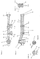
- Fig. 1 an advantageous embodiment of a connection device with features according to the invention is shown.
- a connecting section 10 is provided here between two connecting sections 12, connecting lines 14a, 14b extending from the connecting section 10 and intended for connecting the connecting device according to the invention to the line network of a heating system.
- the connecting portions 12 are intended to be screwed to a manifold of a radiator, in particular a ladder-shaped Röhrenradiators (not shown) with a threaded portion 12 b.
- a seal is made via a sealing ring 12 e, which is supported on the body of the connection portion 12.
- a sealing plug 12c With a lid 12d formed as a nut, which can be connected to the body of the terminal portion 12 via a gasket 12f.
- a connecting piece 12 a extends from the body 12 and serves to connect the connecting portion 10.
- connection section can be realized in different ways. It is thus possible to saw off the bottom heating tube in the case of a conductor radiator and to insert the remaining tube stumps extending from the collecting tube as connections for the connecting section 10.
- the headers may also be laterally formed with screw connections, for example, to screw a nozzle such as the nozzle 12a directly to a manifold of a Leitradiators can.
- connection portion 10 and the connecting portions 12 extend adaptation line sections 16, 18, which adapt the connecting portion 10 to different width radiator.
- the one adaptation line section 18 in a line section 24 of the connecting section 10 for example, welded, soldered.
- any mechanically stable, temperature-resistant and liquid-tight connection technology can be used to fix the adaptation line section 18 to the connection section 10.
- On the opposite side of the adaptation line section 16 is realized by means of a union nut 16a and a screw thread portion 16b to the connecting portion 10 at the same time as a tolerance compensation section.
- connection piece 12a While the adaptation line section 16 is brought into a press-sealing installation on the side of the connection piece 12a, on the opposite side there is a free space between the end of the connection piece 10 facing the connection section 10 Adaption line section 16 and the connecting portion 10 is provided, which is variable without the terminal would be leaking. That is, manufacturing tolerances of the radiator to be connected can be compensated in the axial direction of the connecting portion 10 by the free spaces provided here.
- the connecting section 10 has two line sections 32, 34 which overlap in the region of the connecting lines 14a, 14b. While the one line section 34, which is assigned here to the return of the radiator, the return line 14 b is assigned to the heating system, the connection line 14 a, which is assigned to the flow of the heating system, connected to the line 32.
- connection openings 28a, b as well as 30a, b of the connection lines 14a, 14b can each be closed by, for example, grub screws 26, which are closed in the openings 28b and 30a to be closed in each case. The resulting flow guidance can be seen from the black arrows.
- the heating medium is introduced via the connecting line 14a in the connecting line 32 and introduced via a line section 20 which runs out of the axial direction of the connecting portion 10 in a valve seat 22 into which a valve of conventional type 40 is screwed sealingly. From there, the heating medium is introduced via the connection section 24 into the adaptation line section 18 and introduced via the connection section 12 into one of the manifolds of the radiator to be connected.
- the heating medium flows through the heating tubes (not shown) in the opposite manifold and from there via the connection portion 12 and the adaptation line section 16 shown here right, the tolerance compensation section 16a, 16b in the line 34 of the connecting portion 10 and from there through the Opening 30b in the connecting line 14b from which the cooled heating medium is introduced into the piping of the heating system.
- a closure plug 37 is screwed, soldered, glued or the like at one end of this line section and opposite and is between the Outer wall of the connecting portion 10 and a partition wall 33 between the lines 32, 34 also arranged a closure member 36 liquid-tight.
- the closure parts 36, 37 are to be arranged due to production in order to be able to set up the necessary flow guidance.
- the connecting lines 14a, 14b are assigned to the heating system with respect to the illustration according to FIG. Accordingly, here the opening 30 b is sealed by a closure 26 and the used heating medium flows through the opening 28 b in the return to the heating system. Conversely, as shown in FIG. 2, the opening 30a is continuous and heating medium from the flow of the heating system flows via the connecting line 14b in the line 32 and from there into the radiator.
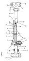
- a connecting portion 10 is shown partly in a sectional view and partly in a front view.
- the connecting lines 14a, 14b are formed so that they can be attached, for example by means of union nuts on the flow and the return of the heating system.
- the connecting line 20 a which runs out of the axial direction of the connecting portion 10, provides the connection between the line 32 according to FIGS. 1 and 2 and the valve seat 22.
- the connecting portion is easily recognizable as an oval tube formed, which is surrounded by a pipe sleeve 42.
- the connection lines 32, 34 are formed, which are connected to the connection line 14b via the openings 30a, 30b.
- the openings 30a, 30b may be partially formed with threads in order to screw a closure in one of the openings 30a, b can.
- the section BB according to FIG. 3b shows a cross section of the connection line 14b and can be seen that this is also formed with respect to the openings 30a, b as an oval tube.
- the cross-section C-C of FIG. 3c shows the cross-sectional shape of the connecting portion 10 in the region of the outgoing from the axial main extension direction of the connecting portion line 20 and 20a.
- the connecting portion 10 it is thus possible to turn into a correspondingly formed radiator formed as tees fittings 12 to which the connecting portion 10 can be applied according to the invention.
- the T-pieces or connection sections 12 are to be placed with inwardly pointing connecting pieces in order to be able to start the connecting section 10.
- the adaptation line sections are to be selected and arranged according to the size or width of the radiator.
- connection device 10 The illustrated in Fig. 5 embodiment of a connection device 10 'with features according to the invention largely corresponds to the embodiments described above.
- a significant change is that between the connecting pieces 12 and the connecting portion 10 is a modification with respect to the adaptation line sections 16 ', 18' and the tolerance compensation sections 16a 'associated therewith, which also take the form of union nuts, which form a soft-sealing screw for tolerance compensation make available, can be recognized. So are here at both ends of the connecting portion 10 'receiving portions 16c, 24 provided in the adaptation line sections 16', 18 'welded, brazed, glued or otherwise how liquid-tight are used. At the respective ends of the adaptation line sections 16 ', 18' tolerance compensation sections 16a 'are attached, which are attached by means of threaded connection 12a' to the connection sections liquid-tight.
- the tolerance compensation sections 16a ' are designed as union nuts in order to enable a soft-sealing screw connection which comes about a compression of the sealing region 16b' to conditions.
- a tolerance range 17 in the threaded connection of the connection section 12 on the left-hand side according to FIG. 5 is shown purely schematically.
- the embodiment shown here according to FIG. 5 can also be designed such that again only one adaptation line section in the form of the section 16 'is provided in order to adapt the device according to the invention to different radiator dimensions or radiator types, while the other adaptation line section 18' only as in the embodiment according to FIGS. 1 and 2, for connecting the radiator to the device 10 'according to the invention.
- inventive device according to FIGS. 1 to 5 or any device according to the invention, which falls under the appended claims, can of course also be applied to panel radiators, for example to those which are installed vertically.
- the manifolds of Walker effetsregisters can be connected as well as the manifolds of a corresponding tubular heater on the inventive device to a heating network.
Landscapes
- Engineering & Computer Science (AREA)
- Physics & Mathematics (AREA)
- Thermal Sciences (AREA)
- Chemical & Material Sciences (AREA)
- Combustion & Propulsion (AREA)
- Mechanical Engineering (AREA)
- General Engineering & Computer Science (AREA)
- Steam Or Hot-Water Central Heating Systems (AREA)
- Flanged Joints, Insulating Joints, And Other Joints (AREA)
- Lock And Its Accessories (AREA)
- Pipe Accessories (AREA)
- Details Of Heat-Exchange And Heat-Transfer (AREA)
Claims (7)
- Dispositif de raccordement pour un corps chauffant ou radiateur, en particulier avec des tubes collecteurs, s'étendant parallèlement les uns aux autres à une certaine distance mutuelle et des tubes chauffants ou des corps chauffants plats s'étendant en position intermédiaire, pour le raccordement à un départ et à un retour, ou à une installation de chauffage,
où le dispositif de raccordement présente un tronçon de liaison (10, 10') disposé entre deux tronçons de raccordement (12), avec des conduites de raccordement (14a, 14b) susceptibles d'être raccordées au départ et au retour de l'installation de chauffage,
caractérisé en ce que
les tronçons de raccordement (12) présentent chacun des tubulures de raccordement (12a) et des tronçons filetés (12b) à l'aide desquels les tronçons de raccordement (12) sont susceptibles d'être reliés, en pouvant être fixés, au corps chauffant, et où les tubulures de raccordement (12a) sont fixées au tronçon de liaison (10, 10'), par l'intermédiaire de tronçons de conduite d'adaptation (16, 18),
en ce qu'une soupape (40) est disposée dans le tronçon de liaison (10, 10'), et
en ce que le tronçon de liaison (10, 10') présente au moins un tronçon de compensation de tolérance (16a, 16b, 16a', 16b'), disposé entre l'un des tronçons de conduite d'adaptation (16, 18) et une zone d'extrémité voisine du tronçon de liaison (10, 10'). - Dispositif de raccordement selon la revendication 1, caractérisé en ce que le tronçon de liaison définit, d'une extrémité à l'autre extrémité, une direction d'étendue principale sensiblement axiale, en ce qu'un premier tronçon de conduite (32, 34) s'étend dans la direction d'étendue principale, en ce qu'un autre tronçon de conduite (20), relié au premier tronçon de conduite (32, 34), s'écarte de la direction d'étendue principale, en ce que l'autre tronçon de conduite (20) est relié à un logement à soupape (22) situé transversalement par rapport à la direction d'étendue principale, afin de recevoir la soupape (40), et en ce qu'un tronçon de raccordement (24) se raccorde au logement à soupape (22), dans la direction d'étendue principale.
- Dispositif de raccordement selon la revendication 1 ou 2, caractérisé en ce que, dans la zone des embouchures des conduites de raccordement (14a, 14b) à l'installation de chauffage, le tronçon de liaison (10) est subdivisé en direction axiale, au moyen d'une subdivision (33), pour définir dans le tronçon de liaison (10) les conduites (32, 34) nécessaires pour un départ et un retour au corps chauffant.
- Dispositif de raccordement selon l'une des revendications 1 à 3, caractérisé en ce que, entre les embouchures des conduites de raccordement (14a, 14b), peut-être inséré un tronçon de séparation, devant aménager un guidage forcé de l'écoulement.
- Dispositif de raccordement selon l'une des revendications 1 à 4, caractérisé en ce qu'à chacune des embouchures des conduites de raccordement (14a, 14b), en partant du tronçon de liaison (10), sont associées respectivement deux ouvertures (28a, 28b, 30a, 30b), une des chaque fois deux ouvertures (28a, 28b, 30a, 30b) étant reliée à la conduite (32), prévue pour le départ, et l'autre des chaque fois deux ouvertures (28a, 28b, 30a, 30b) étant reliée à la conduite (34), prévue pour le retour.
- Dispositif de raccordement selon la revendication 5, caractérisé en ce que chacune des ouvertures des embouchures des conduites de raccordement (14a, 14b) est obturable, individuellement ou au moyen du tronçon de séparation.
- Dispositif de raccordement selon l'une ou plusieurs des revendications précédentes, caractérisé en ce que chaque fois un dispositif de compensation de tolérance (16a) est prévu sur les deux côtés du tronçon de liaison (10').
Applications Claiming Priority (2)
| Application Number | Priority Date | Filing Date | Title |
|---|---|---|---|
| DE10014454A DE10014454B4 (de) | 2000-03-23 | 2000-03-23 | Anschlusseinrichtung für einen Heizkörper |
| DE10014454 | 2000-03-23 |
Publications (3)
| Publication Number | Publication Date |
|---|---|
| EP1136765A2 EP1136765A2 (fr) | 2001-09-26 |
| EP1136765A3 EP1136765A3 (fr) | 2003-08-06 |
| EP1136765B1 true EP1136765B1 (fr) | 2006-03-01 |
Family
ID=7636065
Family Applications (1)
| Application Number | Title | Priority Date | Filing Date |
|---|---|---|---|
| EP00127246A Expired - Lifetime EP1136765B1 (fr) | 2000-03-23 | 2000-12-15 | Dispositif de raccordement pour un radiateur |
Country Status (5)
| Country | Link |
|---|---|
| EP (1) | EP1136765B1 (fr) |
| AT (1) | ATE319056T1 (fr) |
| CZ (1) | CZ20011054A3 (fr) |
| DE (3) | DE10014454B4 (fr) |
| PL (1) | PL346384A1 (fr) |
Families Citing this family (6)
| Publication number | Priority date | Publication date | Assignee | Title |
|---|---|---|---|---|
| DE20204523U1 (de) | 2001-03-23 | 2002-07-04 | Kermi Gmbh, 94447 Plattling | Winkelstück für eine Anschlusseinrichtung eines Heizkörpers |
| ATE373805T1 (de) * | 2002-11-13 | 2007-10-15 | T M S Tuerker Makina Sanayi Ve | Platten-heizkörper mit modular aufgebauten, in der länge anpassbaren verbindungsleitungen zwischen dem mittigem anschluss des heizkörpers und seinem seitlich oben liegendem ventilgehäuse |
| DE102004019207B3 (de) * | 2004-04-16 | 2005-08-04 | Kermi Gmbh | Anschlussarmatur für einen Heizkörper |
| DE202009003179U1 (de) | 2009-03-10 | 2010-07-22 | Hans Berg Gmbh & Co. Kg | Verschlusskappe |
| DE102011050475A1 (de) * | 2011-05-19 | 2012-11-22 | Caradon Stelrad B.V. | Ventileinsatzelement |
| EP2525121B1 (fr) | 2011-05-19 | 2017-06-14 | Caradon Stelrad B.V. | Élément de garniture de soupape |
Family Cites Families (16)
| Publication number | Priority date | Publication date | Assignee | Title |
|---|---|---|---|---|
| GB1518797A (en) * | 1974-10-03 | 1978-07-26 | Fellingsbro Verkstaeder | Valves |
| GB2067735A (en) * | 1980-01-19 | 1981-07-30 | Vervoort J W R | Heating installation |
| EP0045477B1 (fr) * | 1980-08-04 | 1984-10-10 | Hans-Rudolf Guggisberg | Dispositif pour monter une soupape nouvelle à un radiateur d'une installation de chauffage central |
| DE3508932A1 (de) * | 1985-03-13 | 1986-09-18 | Gerhard Christian 7129 Brackenheim Rambacher | Anschlusssystem fuer heizkoerper |
| GB8705536D0 (en) * | 1987-03-10 | 1987-04-15 | Mackrell R W | Moving radiator from places |
| GB2220717A (en) * | 1988-07-12 | 1990-01-17 | Peter Arkley | Flexible couplings for radiators |
| DE19512364C2 (de) * | 1995-04-01 | 1997-02-06 | Berg Hans Gmbh & Co Kg | Anschlußanordnung für einen Röhrenheizkörper |
| DE29618611U1 (de) * | 1995-10-30 | 1997-07-24 | Vogel & Noot Wärmetechnik AG, Wartberg | Heizkörper, insbesondere Rohrheizkörper, Zu- und Ablaufrohr für denselben |
| IT1290557B1 (it) * | 1997-02-27 | 1998-12-10 | Stefano Fracchia | Raccordo per valvole d'intercettazione di fluidi con elemento deviatore interno ruotabile per il mantenimento della direzione del |
| DE19747274A1 (de) * | 1997-10-25 | 1999-04-29 | Vasco Nv | Röhrenheizkörper mit unterem Anschluß |
| IT242897Y1 (it) * | 1997-12-19 | 2002-02-04 | Agis Spa | Radiatore per impianto di riscaldamento centralizzato |
| DE19800487A1 (de) * | 1998-01-09 | 1999-07-15 | Vasco Nv | Röhrenheizkörper mit innerem Rohr |
| DE19813514A1 (de) * | 1998-03-26 | 1999-09-30 | Kermi Gmbh | Steckverbindung |
| DE19813946C1 (de) * | 1998-03-28 | 1999-05-12 | Oventrop Sohn Kg F W | Röhrenheizkörper |
| DE29807226U1 (de) * | 1998-04-21 | 1998-07-16 | Kermi Gmbh, 94447 Plattling | HS-Heizkörper |
| DE19912821C2 (de) * | 1999-03-22 | 2002-09-26 | Kermi Gmbh | Ventilanordnung |
-
2000
- 2000-03-23 DE DE10014454A patent/DE10014454B4/de not_active Expired - Fee Related
- 2000-12-15 AT AT00127246T patent/ATE319056T1/de not_active IP Right Cessation
- 2000-12-15 DE DE50012299T patent/DE50012299D1/de not_active Expired - Lifetime
- 2000-12-15 EP EP00127246A patent/EP1136765B1/fr not_active Expired - Lifetime
-
2001
- 2001-03-11 PL PL01346384A patent/PL346384A1/xx not_active IP Right Cessation
- 2001-03-22 CZ CZ20011054A patent/CZ20011054A3/cs unknown
- 2001-03-23 DE DE20105092U patent/DE20105092U1/de not_active Expired - Lifetime
Also Published As
| Publication number | Publication date |
|---|---|
| PL346384A1 (en) | 2001-09-24 |
| EP1136765A3 (fr) | 2003-08-06 |
| ATE319056T1 (de) | 2006-03-15 |
| CZ20011054A3 (cs) | 2002-02-13 |
| DE50012299D1 (de) | 2006-04-27 |
| EP1136765A2 (fr) | 2001-09-26 |
| DE10014454B4 (de) | 2007-08-16 |
| DE10014454A1 (de) | 2001-10-11 |
| DE20105092U1 (de) | 2001-06-28 |
Similar Documents
| Publication | Publication Date | Title |
|---|---|---|
| DE19603398B4 (de) | Heizungsanschlussvorrichtung, Verteiler und Bauelement für Heizungen | |
| EP1130342B1 (fr) | Module pour installation de chauffage compacte | |
| DE29704807U1 (de) | Anschlußkasten | |
| EP2093517B1 (fr) | Composant pour installation de chauffage compacte | |
| DE10014454B4 (de) | Anschlusseinrichtung für einen Heizkörper | |
| EP1161645B1 (fr) | Radiateur | |
| DE29511076U1 (de) | Heizkörperanordnung | |
| DE4345037C2 (de) | Vorrichtung zum Anschließen eines Heizkörpers, sowie mittenangeschlossener Heizkörper | |
| EP0763181B1 (fr) | Dispositif de chauffage | |
| EP3591268A1 (fr) | Connecteur de conduite de fluide pourvu de pièce d'insertion fixe destinée à l'étranglement | |
| EP1884723B1 (fr) | Module | |
| DE3736107C2 (fr) | ||
| DE19744482C1 (de) | Anschlußsystem für Heizkörper | |
| DE29715784U1 (de) | Ventilgruppe für Fußbodenheizungen | |
| DE19906906C2 (de) | Installationssystem für Heizungsanlagen | |
| AT404068B (de) | Heizungsventil, insbesondere für eine einrohrheizungsanlage | |
| DE3713625C1 (de) | Kondensatabscheider | |
| DE3821372A1 (de) | Leitungsanordnung fuer frischwasser | |
| DE19860781B4 (de) | Variabel anschließbarer Plattenheizkörper | |
| DE3815992A1 (de) | Einrichtung zur fuehrung eines stroemungsmediums | |
| EP2093516B1 (fr) | Composant pour installation de chauffage compacte | |
| DE19802912C2 (de) | Mittel zur Anpassung des Normabstandes eines bauseits vorhandenen Heizkörperanschlusses für Radiatoren und dgl. an einen anderen Heizkörpernabenabstand, insbesondere von Heizplatten | |
| DE10005668B4 (de) | Röhrenheizkörper mit umlaufenden Heizröhren | |
| DE102006043801B4 (de) | Bauteil zum Kreuzen von mit einem Medium durchströmbaren Rohrleitungen | |
| DE4029512A1 (de) | Medienerhitzer, insbesondere dampferzeuger |
Legal Events
| Date | Code | Title | Description |
|---|---|---|---|
| PUAI | Public reference made under article 153(3) epc to a published international application that has entered the european phase |
Free format text: ORIGINAL CODE: 0009012 |
|
| AK | Designated contracting states |
Kind code of ref document: A2 Designated state(s): AT BE CH CY DE DK ES FI FR GB GR IE IT LI LU MC NL PT SE TR |
|
| AX | Request for extension of the european patent |
Free format text: AL;LT;LV;MK;RO;SI |
|
| PUAL | Search report despatched |
Free format text: ORIGINAL CODE: 0009013 |
|
| AK | Designated contracting states |
Designated state(s): AT BE CH CY DE DK ES FI FR GB GR IE IT LI LU MC NL PT SE TR |
|
| AX | Request for extension of the european patent |
Extension state: AL LT LV MK RO SI |
|
| 17P | Request for examination filed |
Effective date: 20031014 |
|
| AKX | Designation fees paid |
Designated state(s): AT CH DE FR GB LI |
|
| 17Q | First examination report despatched |
Effective date: 20050223 |
|
| GRAP | Despatch of communication of intention to grant a patent |
Free format text: ORIGINAL CODE: EPIDOSNIGR1 |
|
| GRAS | Grant fee paid |
Free format text: ORIGINAL CODE: EPIDOSNIGR3 |
|
| GRAA | (expected) grant |
Free format text: ORIGINAL CODE: 0009210 |
|
| AK | Designated contracting states |
Kind code of ref document: B1 Designated state(s): AT CH DE FR GB LI |
|
| REG | Reference to a national code |
Ref country code: GB Ref legal event code: FG4D Free format text: NOT ENGLISH |
|
| REG | Reference to a national code |
Ref country code: CH Ref legal event code: EP |
|
| REF | Corresponds to: |
Ref document number: 50012299 Country of ref document: DE Date of ref document: 20060427 Kind code of ref document: P |
|
| REG | Reference to a national code |
Ref country code: CH Ref legal event code: NV Representative=s name: TROESCH SCHEIDEGGER WERNER AG |
|
| GBT | Gb: translation of ep patent filed (gb section 77(6)(a)/1977) |
Effective date: 20060621 |
|
| ET | Fr: translation filed | ||
| PG25 | Lapsed in a contracting state [announced via postgrant information from national office to epo] |
Ref country code: CH Free format text: LAPSE BECAUSE OF NON-PAYMENT OF DUE FEES Effective date: 20061231 Ref country code: LI Free format text: LAPSE BECAUSE OF NON-PAYMENT OF DUE FEES Effective date: 20061231 |
|
| PLBE | No opposition filed within time limit |
Free format text: ORIGINAL CODE: 0009261 |
|
| STAA | Information on the status of an ep patent application or granted ep patent |
Free format text: STATUS: NO OPPOSITION FILED WITHIN TIME LIMIT |
|
| 26N | No opposition filed |
Effective date: 20061204 |
|
| REG | Reference to a national code |
Ref country code: CH Ref legal event code: PL |
|
| GBPC | Gb: european patent ceased through non-payment of renewal fee |
Effective date: 20061215 |
|
| REG | Reference to a national code |
Ref country code: FR Ref legal event code: ST Effective date: 20070831 |
|
| PG25 | Lapsed in a contracting state [announced via postgrant information from national office to epo] |
Ref country code: GB Free format text: LAPSE BECAUSE OF NON-PAYMENT OF DUE FEES Effective date: 20061215 |
|
| PG25 | Lapsed in a contracting state [announced via postgrant information from national office to epo] |
Ref country code: AT Free format text: LAPSE BECAUSE OF NON-PAYMENT OF DUE FEES Effective date: 20061215 |
|
| PG25 | Lapsed in a contracting state [announced via postgrant information from national office to epo] |
Ref country code: FR Free format text: LAPSE BECAUSE OF NON-PAYMENT OF DUE FEES Effective date: 20070102 |
|
| REG | Reference to a national code |
Ref country code: GB Ref legal event code: S117 Free format text: REQUEST FILED; REQUEST FOR CORRECTION TO THE TRANSLATION UNDER SECTION 117 FILED ON 24 JULY 2006 Ref country code: GB Ref legal event code: S117 Free format text: CORRECTIONS ALLOWED; REQUEST FOR CORRECTION TO THE TRANSLATION UNDER SECTION 117 FILED ON 24 JULY 2006 ALLOWED ON 3 MARCH 2009 |
|
| PGFP | Annual fee paid to national office [announced via postgrant information from national office to epo] |
Ref country code: DE Payment date: 20151208 Year of fee payment: 16 |
|
| REG | Reference to a national code |
Ref country code: DE Ref legal event code: R119 Ref document number: 50012299 Country of ref document: DE |
|
| PG25 | Lapsed in a contracting state [announced via postgrant information from national office to epo] |
Ref country code: DE Free format text: LAPSE BECAUSE OF NON-PAYMENT OF DUE FEES Effective date: 20170701 |