EP1136894B1 - Dispositif de retour à zéro d'un chronographe - Google Patents
Dispositif de retour à zéro d'un chronographe Download PDFInfo
- Publication number
- EP1136894B1 EP1136894B1 EP00810240A EP00810240A EP1136894B1 EP 1136894 B1 EP1136894 B1 EP 1136894B1 EP 00810240 A EP00810240 A EP 00810240A EP 00810240 A EP00810240 A EP 00810240A EP 1136894 B1 EP1136894 B1 EP 1136894B1
- Authority
- EP
- European Patent Office
- Prior art keywords
- shuttle
- return
- fork
- hammer
- zero
- Prior art date
- Legal status (The legal status is an assumption and is not a legal conclusion. Google has not performed a legal analysis and makes no representation as to the accuracy of the status listed.)
- Expired - Lifetime
Links
Images


Classifications
-
- G—PHYSICS
- G04—HOROLOGY
- G04F—TIME-INTERVAL MEASURING
- G04F7/00—Apparatus for measuring unknown time intervals by non-electric means
- G04F7/04—Apparatus for measuring unknown time intervals by non-electric means using a mechanical oscillator
- G04F7/08—Watches or clocks with stop devices, e.g. chronograph
- G04F7/0842—Watches or clocks with stop devices, e.g. chronograph with start-stop control mechanisms
- G04F7/0852—Watches or clocks with stop devices, e.g. chronograph with start-stop control mechanisms with member having a rotational two-way movement, e.g. navette
Definitions
- the present invention relates to a timepiece, in particular a return device to zero of a chronograph.
- the chronographs usually used have two pushers, one for the START / STOP function and the other for the RESET function, see for example GB 1 412 340. There is nevertheless another family of chronographs that use the reset in flight.
- the principle is based on the support of a single pusher which causes the return of the needle at noon and, when the pusher is released, the needle is released. This function was introduced for pilots who must stay on course for a certain time and change to another heading based on information received.
- Such a system can not guarantee long-term reliability, because of the different directions of rotation generated by the position of the mobiles having the cores.
- the friction can cause a wear of the clutch of the wheel and moreover, the hearts being arranged on indirect wheels, the precision during the return to zero relates to the sets of gears.
- a maintenance of the pressure on the hammer, by the opposing pairs of cogs, causes a stop of the watch.
- the object of the present invention is to have a friction clutch system that does not have the disadvantages mentioned above.
- a flight reset device comprising a friction clutch actuated by main disengaging means, a control pushbutton and a reset heart mechanism.
- This device is characterized in that it comprises secondary disengaging means acting when the control pusher actuates the mechanism of the hearts.
- friction clutch is meant a clutch with two discs, held under pressure by an elastic member. During the flight return function, the clutch is disengaged leaving free a hammer actuated by the pressure on the stop button, and which acts on the counters mounted on a friction, said hammer being raised by a spring.
- FIG. 1 describes the system in the engaged state, a figure on which a clutch 1 with two disks 2, 3 held in pressure under the action of a spring 12 can be distinguished, ensuring a greater accuracy of starting the measurement of a short time.
- the clutch 1 is in constant engagement with the wheel of the watch in known manner by one of the wheels 11 of said train meshing with the wheel 3 .
- the separation of the disks 2 , 3 of the clutch 1 is obtained by a known mechanism of a chronograph function by means of a movable fork 7 actuated by a cam 10 , said fork 7 being maintained by pressure under the effect of a spring 8 .
- the flight return function is operated by a hammer 4 actuated by the pressure of the STOP pusher and acting on the counters 5 , 6 mounted on a friction, said hammer being raised by a spring 15 .
- the clutch 1 when returning to zero on the fly, the clutch 1 is then disengaged as illustrated in Figures 2 and 3 .
- This is achieved by a shuttle A having an inclined plane B , said shuttle A being actuated by a pin C integral with the hammer 4 .
- the connection between the hammer 4 and the shuttle A is effected by an opening D placed on the shuttle A.
- the pressure on the pusher of the watch causes, by means of an intermediate lever 9 , the hammer 4 which will actuate the two cores 5, 6 integral with the wheels carrying the display hands.
- the hearts are positioned instantly on the planes 20, 30 resting on the hammer 4 .
- the disengagement timer is synchronized by the pin C which simultaneously drives the shuttle A which, by its inclined plane B , will raise the fork 7 , thus disengaging the clutch 1 .
- the time delay is obtained by the position of the pin C which is slightly ahead of the action of the hearts 5, 6.
- the shuttle A is not integral with the hammer 4 .
- the shuttle A is pushed by the hammer 4 , and the return to the clutch position is provided by a spring Z.
- the shuttle acts on the fork 7 tangentially by means of different inclined planes.
- the inclined plane described above on the shuttle A is located on the fork 7 .
- the shuttle as well as the fork has inclined planes.
Landscapes
- Physics & Mathematics (AREA)
- General Physics & Mathematics (AREA)
- Measurement Of Unknown Time Intervals (AREA)
Description
- La présente invention a pour objet une pièce d'horlogerie, en particulier un dispositif de retour à zéro d'un chronographe.
- Les chronographes usuellement utilisés possèdent deux poussoirs, l'un pour la fonction START/STOP et l'autre pour la fonction RESET (remise a zéro), voir par exemple GB 1 412 340. Il existe néanmoins une autre famille de chronographe qui utilisent la remise à zéro en vol.
- Le principe est basé sur l'appui d'un seul poussoir qui provoque le retour de l'aiguille à midi et, lorsque le poussoir est relâché, l'aiguille est libérée. Cette fonction a été introduite pour les pilotes qui doivent garder un cap pendant un certain temps et changer pour un autre cap selon une information reçue.
- On connaît de tels systèmes appliqués à des chronographes dont l'enclenchement s'obtient par un engrenage en champ, au moyen d'une roue sur champ montée sur la roue de moyenne du rouage de finissage, laquelle par l'intermédiaire d'un renvoi, s'engrène avec la roue du chronographe. Ce système a une précision relative du fait de la pénétration des dentures d'un pas angulaire différent entre elles.
- De plus, lors d'une fonction de retour en vol, le fait de relever obligatoirement la bascule d'embrayage, comportant la roue sur champ et le renvoi, est complexe.
- Pour réaliser l'entraînement du mécanisme, un autre système est connu utilisant un embrayage par friction. Ce système a l'avantage d'être très précis car indépendant de la pénétration des dentures.
- Un tel système ne peut garantir une fiabilité à long terme, du fait des différents sens de rotation engendrés par la position des mobiles comportant les coeurs. Les frictions peuvent provoquer une usure de l'embrayage de la roue et de plus, les coeurs étant disposés sur des roues indirectes, la précision lors du retour à zéro est relative aux jeux d'engrenages. De surcroît, un maintien de la pression sur le marteau, de par les couples antagonistes des rouages, provoque un arrêt de la montre.
- C'est pourquoi le but de la présente invention est de disposer d'un système d'embrayage à friction qui n'a pas les inconvénients cités ci-dessus.
- Ce but est atteint par un dispositif de remise à zéro en vol comprenant un embrayage à friction, actionné par des moyens de débrayage principaux, un poussoir de commande et un mécanisme de coeurs de remise à zéro. Ce dispositif est caractérisé en ce qu'il comprend des moyens de débrayage secondaires agissant lorsque le poussoir de commande actionne le mécanisme des coeurs.
- Par embrayage à friction, on entend un embrayage à deux disques, maintenus sous pression par un élément élastique. Lors de la fonction de retour en vol, l'embrayage est débrayé laissant alors libre un marteau actionné par la pression sur le poussoir stop, et qui agit sur les coeurs de compteurs montés sur une friction, ledit marteau étant relevé par un ressort.
- La présente invention sera comprise plus en détail grâce aux dessins suivants, pris à titre non limitatifs, dans lesquels:
- la figure 1 représente le mécanisme à l'état embrayé,
- la figure 2 représente le mécanisme à l'état débrayé,
- la figure 3 représente une vue de dessus du mécanisme de débrayage,
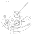
- la figure 4 représente une vue de dessus d'une variante de l'invention.
- La figure 1 décrit le système à l'état embrayé, figure sur laquelle on distingue un embrayage 1 à deux disques 2, 3 maintenus en pression sous l'action d'un ressort 12 assurant une plus grande précision de départ de la mesure d'un temps court. L'embrayage 1 est en prise constante avec le rouage de la montre de manière connue par une des roues 11 dudit rouage s'engrenant avec le mobile 3. La séparation des disques 2, 3 de l'embrayage 1 s'obtient par un mécanisme connu d'une fonction chronographe au moyen d'une fourchette mobile 7 actionnée par une came 10, ladite fourchette 7 étant maintenue par pression sous l'effet d'un ressort 8. La fonction retour en vol s'opère par un marteau 4 actionné par la pression du poussoir STOP et agissant sur les coeurs de compteurs 5, 6 montés sur une friction, ledit marteau étant relevé par un ressort 15.
- Selon l'invention, au moment du retour à zéro à la volée, l'embrayage 1 est alors débrayé tel qu'illustré sur les figures 2 et 3. Ceci s'obtient par une navette A comportant un plan incliné B, ladite navette A étant actionnée par une goupille C solidaire du marteau 4. La liaison entre le marteau 4 et la navette A s'effectuant par une ouverture D placée sur la navette A.
- Lors de la fonction de retour en vol, la pression sur le poussoir de la montre entraîne, au moyen d'une bascule intermédiaire 9, le marteau 4 qui va actionner les deux coeurs 5, 6 solidaires des roues portant les aiguilles d'affichage. Les coeurs se positionnent instantanément sur les plans 20, 30 en appui sur le marteau 4. La temporisation de débrayage est synchronisée par la goupille C qui entraîne simultanément la navette A qui, par son plan incliné B, va lever la fourchette 7, débrayant ainsi l'embrayage 1. La temporisation est obtenue par la position de la goupille C qui se trouve légèrement en avance sur l'action des coeurs 5, 6. Dès cette fonction terminée, un maintien de la pression, par le fait du débrayage, ne provoque pas l'arrêt de la montre.
- En relâchant cette pression, le système est ramené en arrière sous l'effet d'un ressort 15 en liaison avec la goupille C. Le système est ainsi parfaitement synchronisé et le comptage recommence depuis la position initiale.
- Selon une variante de l'invention, la navette A n'est pas solidaire avec le marteau 4. Sur la figure 4, la navette A est poussée par le marteau 4, et le retour à la position d'embrayage est assurée par un ressort Z. La navette agit sur la fourchette 7 de manière tangentielle au moyen de différents plans inclinés.
- Selon une forme d'exécution, le plan incliné décrit précédemment sur la navette A est situé sur la fourchette 7. Selon une autre forme de réalisation, la navette de même que la fourchette comporte des plans inclinés.
- Le présente description est nullement limitative au mode d'actionnement des différents éléments, que ce soit de la navette, ou de l'embrayage. Il existe en effet d'autres pièces connues pour actionner de telles pièces mécaniques.
- Toutes les pièces équivalentes qui visent le même but que l'invention, à savoir le débrayage d'un embrayage à friction d'un chronographe lors de sa remise à zéro en vol, est compris dans la présente invention.
Claims (8)
- Dispositif de remise à zéro en vol pour chronographe, comprenant un embrayage à friction (1), des moyens de débrayage principaux (7, 10), un poussoir de commande et un mécanisme de coeurs de remise à zéro (4, 5, 6), caractérisé en ce qu'il comprend des moyens de débrayage secondaires (A) agissant lorsque le poussoir de commande actionne le mécanisme des coeurs.
- Dispositif selon la revendication 1, caractérisé en ce que les moyens de débrayage principaux comprennent une fourchette (7) et en ce que les moyens de débrayage secondaires comprennent une navette (A) actionnée par un marteau (4) du mécanisme de coeurs.
- Dispositif selon la revendication 2, caractérisé en ce que la navette (A) engage la fourchette (7) par la pression du marteau (4).
- Dispositif selon la revendication 3, caractérisé en ce que l'engagement entre la navette (A) et la fourchette (7) se fait par un plan incliné (B).
- Dispositif selon la revendication 4, caractérisé en ce que le plan incliné est placé sur la navette (A).
- Dispositif selon la revendication 4, caractérisé en ce que le plan incliné est placé sur la fourchette (7).
- Dispositif selon la revendication 4, caractérisé en ce que le plan incliné est placé sur la navette (A) et la fourchette (7).
- Chronographe comprenant le dispositif selon l'une des revendications 1 à 7.
Priority Applications (3)
| Application Number | Priority Date | Filing Date | Title |
|---|---|---|---|
| DE60031236T DE60031236D1 (de) | 2000-03-20 | 2000-03-20 | Vorrichtung für Nullrückstellung in einer Chronographenuhr |
| AT00810240T ATE342526T1 (de) | 2000-03-20 | 2000-03-20 | Vorrichtung für nullrückstellung in einer chronographenuhr |
| EP00810240A EP1136894B1 (fr) | 2000-03-20 | 2000-03-20 | Dispositif de retour à zéro d'un chronographe |
Applications Claiming Priority (1)
| Application Number | Priority Date | Filing Date | Title |
|---|---|---|---|
| EP00810240A EP1136894B1 (fr) | 2000-03-20 | 2000-03-20 | Dispositif de retour à zéro d'un chronographe |
Publications (2)
| Publication Number | Publication Date |
|---|---|
| EP1136894A1 EP1136894A1 (fr) | 2001-09-26 |
| EP1136894B1 true EP1136894B1 (fr) | 2006-10-11 |
Family
ID=8174609
Family Applications (1)
| Application Number | Title | Priority Date | Filing Date |
|---|---|---|---|
| EP00810240A Expired - Lifetime EP1136894B1 (fr) | 2000-03-20 | 2000-03-20 | Dispositif de retour à zéro d'un chronographe |
Country Status (3)
| Country | Link |
|---|---|
| EP (1) | EP1136894B1 (fr) |
| AT (1) | ATE342526T1 (fr) |
| DE (1) | DE60031236D1 (fr) |
Cited By (1)
| Publication number | Priority date | Publication date | Assignee | Title |
|---|---|---|---|---|
| CH722441A1 (fr) * | 2024-12-20 | 2026-06-30 | Parmigiani Fleurier SA | Mécanisme de chronographe et montre comprenant un tel mécanisme |
Families Citing this family (4)
| Publication number | Priority date | Publication date | Assignee | Title |
|---|---|---|---|---|
| DE60210973T2 (de) | 2002-10-04 | 2007-01-04 | Eta Sa Manufacture Horlogère Suisse | Kupplungsmechanismus für Chronographen |
| JP4376536B2 (ja) * | 2003-03-27 | 2009-12-02 | セイコーインスツル株式会社 | 時分発停レバーを有するクロノグラフ時計 |
| EP2410388B1 (fr) * | 2010-07-21 | 2018-04-18 | Blancpain S.A. | Pièce d'horlogerie à double affichage |
| US9146541B2 (en) | 2011-06-29 | 2015-09-29 | Rolex S.A. | Device for resetting to a predetermined position an indicator member indicative of a parameter connected with time |
Family Cites Families (2)
| Publication number | Priority date | Publication date | Assignee | Title |
|---|---|---|---|---|
| CH376072A4 (fr) * | 1972-03-15 | 1974-02-15 | ||
| CH690524A5 (fr) * | 1995-10-31 | 2000-09-29 | Rolex Montres | Pièce d'horlogerie à mécanisme de chronographe. |
-
2000
- 2000-03-20 AT AT00810240T patent/ATE342526T1/de not_active IP Right Cessation
- 2000-03-20 DE DE60031236T patent/DE60031236D1/de not_active Expired - Lifetime
- 2000-03-20 EP EP00810240A patent/EP1136894B1/fr not_active Expired - Lifetime
Cited By (1)
| Publication number | Priority date | Publication date | Assignee | Title |
|---|---|---|---|---|
| CH722441A1 (fr) * | 2024-12-20 | 2026-06-30 | Parmigiani Fleurier SA | Mécanisme de chronographe et montre comprenant un tel mécanisme |
Also Published As
| Publication number | Publication date |
|---|---|
| DE60031236D1 (de) | 2006-11-23 |
| ATE342526T1 (de) | 2006-11-15 |
| EP1136894A1 (fr) | 2001-09-26 |
Similar Documents
| Publication | Publication Date | Title |
|---|---|---|
| EP2221676B1 (fr) | Pièce d'horlogerie comportant un chronographe et une montre | |
| EP2410388B1 (fr) | Pièce d'horlogerie à double affichage | |
| EP0772104B1 (fr) | Pièce d'horlogerie à mécanisme de chronographe | |
| US7918602B2 (en) | Bistable hammer for a chronograph mechanism | |
| EP2541346B1 (fr) | Dispositif de remise dans une position prédéterminée d'un organe indicateur d'une grandeur liée au temps | |
| CN101946214B (zh) | 用于时计的控制部件的抗冲击装置 | |
| WO2005006087A1 (fr) | Dispositif d'affichage pour montre | |
| EP1791043A1 (fr) | Mouvement de chronographe pour pièce d'horlogerie | |
| WO2010100162A1 (fr) | Piece d'horlogerie | |
| CH703797B1 (fr) | Pièce d'horlogerie comportant un chronographe et une foudroyante. | |
| EP1136894A1 (fr) | Dispositif de retour à zéro d'un chronographe | |
| EP3168694B1 (fr) | Mécanisme indicateur de la vitesse ascensionnelle et montre de plongée comportant un tel mécanisme | |
| CH704120A2 (fr) | Chronographe differentiel destine a mesurer et indiquer deux temps distincts ainsi que la difference de ces deux temps. | |
| EP1797481B1 (fr) | Piece d'horlogerie mecanique ou automatique avec dispositif d'indication de la fiabilite de la chronometrie de la piece | |
| EP3845975B1 (fr) | Dispositif de surete et mecanisme de sonnerie | |
| GB1410208A (en) | Time-setter for an electronic timepiece | |
| EP0957415A1 (fr) | Dispositif de poussoir pour pièce d'horlogerie, notamment chronographe | |
| CH175961A (de) | Luftabschlusseinrichtung an Ölfeuerungen. | |
| CH647125GA3 (en) | Chronograph | |
| CH376072A (de) | Teigrundwirkvorrichtung | |
| EP1366471A1 (fr) | Montre mecanique dotee d'un indicateur de cycles hebdomadaires | |
| CH161093A (fr) | Mouvement d'horlogerie à chronographe. | |
| CH287612A (fr) | Pièce d'horlogerie. | |
| CH702157B1 (fr) | Pièce d'horlogerie munie d'un mécanisme de retour en vol. | |
| CH270306A (fr) | Dispositif de remise à l'heure d'un organe indicateur d'une pièce d'horlogerie, notamment de l'aiguille des secondes. |
Legal Events
| Date | Code | Title | Description |
|---|---|---|---|
| PUAI | Public reference made under article 153(3) epc to a published international application that has entered the european phase |
Free format text: ORIGINAL CODE: 0009012 |
|
| AK | Designated contracting states |
Kind code of ref document: A1 Designated state(s): AT BE CH CY DE DK ES FI FR GB GR IE IT LI LU MC NL PT SE |
|
| AX | Request for extension of the european patent |
Free format text: AL;LT;LV;MK;RO;SI |
|
| 17P | Request for examination filed |
Effective date: 20020118 |
|
| AKX | Designation fees paid |
Free format text: AT BE CH CY DE DK ES FI FR GB GR IE IT LI LU MC NL PT SE |
|
| GRAP | Despatch of communication of intention to grant a patent |
Free format text: ORIGINAL CODE: EPIDOSNIGR1 |
|
| GRAS | Grant fee paid |
Free format text: ORIGINAL CODE: EPIDOSNIGR3 |
|
| GRAA | (expected) grant |
Free format text: ORIGINAL CODE: 0009210 |
|
| AK | Designated contracting states |
Kind code of ref document: B1 Designated state(s): AT BE CH CY DE DK ES FI FR GB GR IE IT LI LU MC NL PT SE |
|
| PG25 | Lapsed in a contracting state [announced via postgrant information from national office to epo] |
Ref country code: IT Free format text: LAPSE BECAUSE OF FAILURE TO SUBMIT A TRANSLATION OF THE DESCRIPTION OR TO PAY THE FEE WITHIN THE PRESCRIBED TIME-LIMIT;WARNING: LAPSES OF ITALIAN PATENTS WITH EFFECTIVE DATE BEFORE 2007 MAY HAVE OCCURRED AT ANY TIME BEFORE 2007. THE CORRECT EFFECTIVE DATE MAY BE DIFFERENT FROM THE ONE RECORDED. Effective date: 20061011 Ref country code: IE Free format text: LAPSE BECAUSE OF FAILURE TO SUBMIT A TRANSLATION OF THE DESCRIPTION OR TO PAY THE FEE WITHIN THE PRESCRIBED TIME-LIMIT Effective date: 20061011 Ref country code: NL Free format text: LAPSE BECAUSE OF FAILURE TO SUBMIT A TRANSLATION OF THE DESCRIPTION OR TO PAY THE FEE WITHIN THE PRESCRIBED TIME-LIMIT Effective date: 20061011 Ref country code: AT Free format text: LAPSE BECAUSE OF FAILURE TO SUBMIT A TRANSLATION OF THE DESCRIPTION OR TO PAY THE FEE WITHIN THE PRESCRIBED TIME-LIMIT Effective date: 20061011 Ref country code: FI Free format text: LAPSE BECAUSE OF FAILURE TO SUBMIT A TRANSLATION OF THE DESCRIPTION OR TO PAY THE FEE WITHIN THE PRESCRIBED TIME-LIMIT Effective date: 20061011 |
|
| REG | Reference to a national code |
Ref country code: GB Ref legal event code: FG4D Free format text: NOT ENGLISH |
|
| REG | Reference to a national code |
Ref country code: CH Ref legal event code: EP |
|
| REG | Reference to a national code |
Ref country code: IE Ref legal event code: FG4D Free format text: LANGUAGE OF EP DOCUMENT: FRENCH |
|
| REF | Corresponds to: |
Ref document number: 60031236 Country of ref document: DE Date of ref document: 20061123 Kind code of ref document: P |
|
| PG25 | Lapsed in a contracting state [announced via postgrant information from national office to epo] |
Ref country code: SE Free format text: LAPSE BECAUSE OF FAILURE TO SUBMIT A TRANSLATION OF THE DESCRIPTION OR TO PAY THE FEE WITHIN THE PRESCRIBED TIME-LIMIT Effective date: 20070111 Ref country code: DK Free format text: LAPSE BECAUSE OF FAILURE TO SUBMIT A TRANSLATION OF THE DESCRIPTION OR TO PAY THE FEE WITHIN THE PRESCRIBED TIME-LIMIT Effective date: 20070111 |
|
| PG25 | Lapsed in a contracting state [announced via postgrant information from national office to epo] |
Ref country code: DE Free format text: LAPSE BECAUSE OF FAILURE TO SUBMIT A TRANSLATION OF THE DESCRIPTION OR TO PAY THE FEE WITHIN THE PRESCRIBED TIME-LIMIT Effective date: 20070112 |
|
| PG25 | Lapsed in a contracting state [announced via postgrant information from national office to epo] |
Ref country code: ES Free format text: LAPSE BECAUSE OF FAILURE TO SUBMIT A TRANSLATION OF THE DESCRIPTION OR TO PAY THE FEE WITHIN THE PRESCRIBED TIME-LIMIT Effective date: 20070122 |
|
| PG25 | Lapsed in a contracting state [announced via postgrant information from national office to epo] |
Ref country code: PT Free format text: LAPSE BECAUSE OF FAILURE TO SUBMIT A TRANSLATION OF THE DESCRIPTION OR TO PAY THE FEE WITHIN THE PRESCRIBED TIME-LIMIT Effective date: 20070319 |
|
| NLV1 | Nl: lapsed or annulled due to failure to fulfill the requirements of art. 29p and 29m of the patents act | ||
| GBV | Gb: ep patent (uk) treated as always having been void in accordance with gb section 77(7)/1977 [no translation filed] |
Effective date: 20061011 |
|
| REG | Reference to a national code |
Ref country code: IE Ref legal event code: FD4D |
|
| PLBE | No opposition filed within time limit |
Free format text: ORIGINAL CODE: 0009261 |
|
| STAA | Information on the status of an ep patent application or granted ep patent |
Free format text: STATUS: NO OPPOSITION FILED WITHIN TIME LIMIT |
|
| 26N | No opposition filed |
Effective date: 20070712 |
|
| PG25 | Lapsed in a contracting state [announced via postgrant information from national office to epo] |
Ref country code: GB Free format text: LAPSE BECAUSE OF FAILURE TO SUBMIT A TRANSLATION OF THE DESCRIPTION OR TO PAY THE FEE WITHIN THE PRESCRIBED TIME-LIMIT Effective date: 20061011 |
|
| BERE | Be: lapsed |
Owner name: DTH DUBOIS TECHNIQUE HORLOGERE SA Effective date: 20070331 |
|
| PG25 | Lapsed in a contracting state [announced via postgrant information from national office to epo] |
Ref country code: BE Free format text: LAPSE BECAUSE OF NON-PAYMENT OF DUE FEES Effective date: 20070331 |
|
| REG | Reference to a national code |
Ref country code: FR Ref legal event code: ST Effective date: 20071130 |
|
| PG25 | Lapsed in a contracting state [announced via postgrant information from national office to epo] |
Ref country code: MC Free format text: LAPSE BECAUSE OF NON-PAYMENT OF DUE FEES Effective date: 20070331 |
|
| REG | Reference to a national code |
Ref country code: CH Ref legal event code: NV Representative=s name: GRIFFES CONSULTING SA |
|
| PG25 | Lapsed in a contracting state [announced via postgrant information from national office to epo] |
Ref country code: GR Free format text: LAPSE BECAUSE OF FAILURE TO SUBMIT A TRANSLATION OF THE DESCRIPTION OR TO PAY THE FEE WITHIN THE PRESCRIBED TIME-LIMIT Effective date: 20070112 |
|
| PG25 | Lapsed in a contracting state [announced via postgrant information from national office to epo] |
Ref country code: FR Free format text: LAPSE BECAUSE OF NON-PAYMENT OF DUE FEES Effective date: 20070402 |
|
| PG25 | Lapsed in a contracting state [announced via postgrant information from national office to epo] |
Ref country code: LU Free format text: LAPSE BECAUSE OF NON-PAYMENT OF DUE FEES Effective date: 20070320 Ref country code: CY Free format text: LAPSE BECAUSE OF FAILURE TO SUBMIT A TRANSLATION OF THE DESCRIPTION OR TO PAY THE FEE WITHIN THE PRESCRIBED TIME-LIMIT Effective date: 20061011 |
|
| PGFP | Annual fee paid to national office [announced via postgrant information from national office to epo] |
Ref country code: CH Payment date: 20100416 Year of fee payment: 11 |
|
| REG | Reference to a national code |
Ref country code: CH Ref legal event code: PL |
|
| PG25 | Lapsed in a contracting state [announced via postgrant information from national office to epo] |
Ref country code: LI Free format text: LAPSE BECAUSE OF NON-PAYMENT OF DUE FEES Effective date: 20110331 Ref country code: CH Free format text: LAPSE BECAUSE OF NON-PAYMENT OF DUE FEES Effective date: 20110331 |