EP1136901A2 - Führung für justierbare Konsole auf Pedalarm - Google Patents
Führung für justierbare Konsole auf Pedalarm Download PDFInfo
- Publication number
- EP1136901A2 EP1136901A2 EP01301594A EP01301594A EP1136901A2 EP 1136901 A2 EP1136901 A2 EP 1136901A2 EP 01301594 A EP01301594 A EP 01301594A EP 01301594 A EP01301594 A EP 01301594A EP 1136901 A2 EP1136901 A2 EP 1136901A2
- Authority
- EP
- European Patent Office
- Prior art keywords
- telescoping
- assembly
- telescoping element
- screw member
- set forth
- Prior art date
- Legal status (The legal status is an assumption and is not a legal conclusion. Google has not performed a legal analysis and makes no representation as to the accuracy of the status listed.)
- Withdrawn
Links
- 230000000087 stabilizing effect Effects 0.000 claims abstract description 4
- 230000007246 mechanism Effects 0.000 claims description 6
- 230000004044 response Effects 0.000 claims description 2
- 230000008901 benefit Effects 0.000 description 2
- 230000003993 interaction Effects 0.000 description 2
- 230000000712 assembly Effects 0.000 description 1
- 238000000429 assembly Methods 0.000 description 1
- 230000007613 environmental effect Effects 0.000 description 1
- 230000004048 modification Effects 0.000 description 1
- 238000012986 modification Methods 0.000 description 1
Images

Classifications
-
- B—PERFORMING OPERATIONS; TRANSPORTING
- B60—VEHICLES IN GENERAL
- B60T—VEHICLE BRAKE CONTROL SYSTEMS OR PARTS THEREOF; BRAKE CONTROL SYSTEMS OR PARTS THEREOF, IN GENERAL; ARRANGEMENT OF BRAKING ELEMENTS ON VEHICLES IN GENERAL; PORTABLE DEVICES FOR PREVENTING UNWANTED MOVEMENT OF VEHICLES; VEHICLE MODIFICATIONS TO FACILITATE COOLING OF BRAKES
- B60T7/00—Brake-action initiating means
- B60T7/02—Brake-action initiating means for personal initiation
- B60T7/04—Brake-action initiating means for personal initiation foot actuated
-
- G—PHYSICS
- G05—CONTROLLING; REGULATING
- G05G—CONTROL DEVICES OR SYSTEMS INSOFAR AS CHARACTERISED BY MECHANICAL FEATURES ONLY
- G05G1/00—Controlling members, e.g. knobs or handles; Assemblies or arrangements thereof; Indicating position of controlling members
- G05G1/30—Controlling members actuated by foot
- G05G1/40—Controlling members actuated by foot adjustable
- G05G1/405—Controlling members actuated by foot adjustable infinitely adjustable
-
- Y—GENERAL TAGGING OF NEW TECHNOLOGICAL DEVELOPMENTS; GENERAL TAGGING OF CROSS-SECTIONAL TECHNOLOGIES SPANNING OVER SEVERAL SECTIONS OF THE IPC; TECHNICAL SUBJECTS COVERED BY FORMER USPC CROSS-REFERENCE ART COLLECTIONS [XRACs] AND DIGESTS
- Y10—TECHNICAL SUBJECTS COVERED BY FORMER USPC
- Y10T—TECHNICAL SUBJECTS COVERED BY FORMER US CLASSIFICATION
- Y10T74/00—Machine element or mechanism
- Y10T74/20—Control lever and linkage systems
- Y10T74/20012—Multiple controlled elements
- Y10T74/20189—Foot operated
- Y10T74/20195—Offset extension
-
- Y—GENERAL TAGGING OF NEW TECHNOLOGICAL DEVELOPMENTS; GENERAL TAGGING OF CROSS-SECTIONAL TECHNOLOGIES SPANNING OVER SEVERAL SECTIONS OF THE IPC; TECHNICAL SUBJECTS COVERED BY FORMER USPC CROSS-REFERENCE ART COLLECTIONS [XRACs] AND DIGESTS
- Y10—TECHNICAL SUBJECTS COVERED BY FORMER USPC
- Y10T—TECHNICAL SUBJECTS COVERED BY FORMER US CLASSIFICATION
- Y10T74/00—Machine element or mechanism
- Y10T74/20—Control lever and linkage systems
- Y10T74/20528—Foot operated
-
- Y—GENERAL TAGGING OF NEW TECHNOLOGICAL DEVELOPMENTS; GENERAL TAGGING OF CROSS-SECTIONAL TECHNOLOGIES SPANNING OVER SEVERAL SECTIONS OF THE IPC; TECHNICAL SUBJECTS COVERED BY FORMER USPC CROSS-REFERENCE ART COLLECTIONS [XRACs] AND DIGESTS
- Y10—TECHNICAL SUBJECTS COVERED BY FORMER USPC
- Y10T—TECHNICAL SUBJECTS COVERED BY FORMER US CLASSIFICATION
- Y10T74/00—Machine element or mechanism
- Y10T74/20—Control lever and linkage systems
- Y10T74/20576—Elements
- Y10T74/20888—Pedals
- Y10T74/209—Extension
Definitions
- An adjustable pedal assembly for an automotive vehicle wherein the distance the pedal pad is disposed from the pedal arm may be adjusted.
- a support supports the pedal arm for pivotal movement on a vehicle and a pedal pad receives forces for pivoting the pedal arm to apply the brakes or actuate the throttle in an automotive vehicle.
- An adjuster supports the pedal pad on the distal end of the pedal arm for adjusting the position of the pedal pad relative to the pedal arm along an adjustment axis.
- the invention provides an adjustable pedal assembly for an automotive vehicle wherein a pedal arm having a distal end is supported for pivotal movement on a vehicle by a support.
- a pedal pad receives forces for pivoting the pedal arm relative to the support and an adjuster supports the pedal pad on the distal end of the pedal arm for adjusting the position of the pedal pad relative to the pedal arm along an adjustment axis.
- the assembly is characterized by a guide interconnecting the pad and the pedal arm for stabilizing the movement of the pad relative to the pedal arm along the adjustment axis.
- the subject invention provides an adjustable pedal pad that is adjusted by one adjuster yet is stabilized in lateral movement by a separate guide, i.e., a guide that is independent of the adjuster.
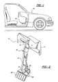
- a first embodiment of an adjustable pedal assembly is generally shown at 12 and a second embodiment is generally shown at 112 for use in an automotive vehicle 10.
- the assembly includes a pedal arm 14, 114 having a distal or lower end and supported by a support 16, 116 supporting the pedal arm 14, 114 for pivotal movement on a vehicle 10.
- the support 16, 116 comprises a shaft, which is supported on the vehicle 10 by a bracket 17, or the like.
- the pedal arm 14, 114 may be rotated on the shaft or fixed to the shaft with the shaft rotatable relative to the vehicle 10.
- a control attachment 18, 118 is included on the pedal arm 14, 114 for connection to a brake or accelerator control.
- a pedal pad 20,120 receives forces for pivoting the pedal arm 14, 114 and an adjuster, generally shown at 22 and 122, supports the pedal pad 20,120 on the distal end of the pedal arm 14, 114 for adjusting the position of the pedal pad 20,120 relative to the pedal arm 14, 114 along an adjustment axis A.
- the assembly is characterized by a separate and independent guide interconnecting the pedal pad 20,120 and the pedal arm 14, 114 for stabilizing the movement of the pedal pad 20,120 relative to the pedal arm 14, 114 along the adjustment axis A.
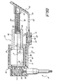
- the guide includes a first telescoping element 24, 124 and a second telescoping element 26, 126 which are in sliding engagement with one another along a telescoping axis that is parallel to the adjustment axis A.
- the telescoping axis is parallel to and spaced from the adjustment axis A in the first embodiment of Figures 2-5 whereas the telescoping axis is coaxial with the adjustment axis A in the embodiment of Figures 6 and 7.
- a tongue and groove connection 28, 128 prevents the first telescoping element 24, 124 from rotating relative to the second telescoping element 26, 126 about the telescoping axis.
- the adjuster 22, 122 includes a plurality of screw members interconnected by threads for adjusting the position of the pedal pad 20,120 along the adjustment axis A in response to relative rotation between the screw members. More specifically, a first screw member 30, 130 is rotatably supported by a housing 32, 132. The housing 132 in the second embodiment is in two parts 132a ands 132b, which are secured together by appropriate fasteners.
- a non-rotatable connection 34, 134a and 134b interconnects a second 36, 136 of the screw members and the pedal pad 20,120.
- the pedal pad 120 of the second embodiment includes a U-shaped clip 135 which slides over the washer-like portion 134a of the non-rotatable connection and pins 133 extend through holes 137 to interconnect the portion 134a and the clip 135.
- a first operative connection 38, 138a and 138b connects the first telescoping element 24, 124 to the housing 32, 132 for preventing relative rotation between the first telescoping element 24, 124 and the housing 32, 132.
- the first telescoping element 24 in the first embodiment is defined by a slideway in the housing 32 and the first operative connection 38 connecting the first telescoping element 24 to the housing 32 is defined by an integral portion of the housing 32.
- the first operative connection 138a and 138b in second embodiment that connects the first telescoping element 124 to the housing 32, 132 comprises a mechanical interlock defined by keys 138a which engage the slots 138b in the housing 132b.
- a snap ring 139 snaps into an annular groove in the end of the first telescoping element 124 to axially retain the first telescoping element 124 to the housing 132b. Accordingly, the first operative connection 38, 138a and 138b connects the first telescoping element 24, 124 to the housing 32, 132 to prevent relative axial movement between the first telescoping element 24, 124 and the housing 32, 132.
- a second operative connection 40, 140a and 140b connects the second telescoping element 26, 126 to the second screw member 36, 136 for preventing relative rotation between the second telescoping element 26, 126 and the second screw member 36, 136.
- This second operative connection 40, 140a and 140b which connects the second telescoping element 26, 126 to the second screw member 36, 136, permits relative axial movement between the second screw member 36, 136 and the second telescoping element 26, 126 as the second telescoping element 26, 126 moves along the telescoping axis relative to the first telescoping element 24, 124
- the second operative connection 40 which connects the second telescoping element 26 to the second screw member 36 in the first embodiment comprises an integral portion of the pedal pad 20.
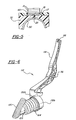
- a pair of plates 15 are fastened to the housing 32 to define the groove of the connection 28.
- a bottom plate 17 of the second telescoping element 26 defines the tongue of the connection 28 and is slidably disposed under the plates 15.
- Another plate 19 is slidably disposed between the side plates 15 and is sandwiched with the connecting slide 40 by a block 21.
- fasteners 23 which allow the plate 17 to slide in the groove of the connection 28 and the block 23 and plate 19 to slide relative to the integral connection 40 of the pedal pad 20.
- the second telescoping element 26 may be non-axially movable relative to either the pedal pad connection 40 or to the housing 32.
- the second telescoping element 26 is slidable relative to both as the fasteners 23 slide along a slot 25 in the connecting portion 40.
- the second operative connection 140a and 140b which connects the second telescoping element 126 to the second screw member 136 in the second embodiment comprises co-acting splines on the outside of the second telescoping element 126 and on the inside of the second screw member 136.
- the plurality of screw members includes an intermediate screw member 42, 142 having first threads 44, 144 in threaded engagement with the first screw member 30, 130 and second threads 46, 146 in threaded engagement with the second screw member 36, 136.
- the intermediate screw member 42, 142 is cylindrical with the first threads 44, 144 disposed about the exterior thereof and threadedly engaging the interior teeth 45, 145 of the first screw member 30, 130 and with the second threads 46, 146 disposed about the interior thereof and threadedly engaging threads 48, 148 on the exterior of the second screw member 36, 136.
- the assembly also includes a drive mechanism for rotating the first screw member 30, 130.
- the drive mechanism includes a driven helical cable 50 which engages a gear 52 which, in turn, rotates the first screw member 30.
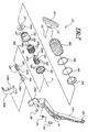
- the drive mechanism includes bevel gear 150 which meshes with a drive ring 152.
- the bevel gear 150 is rotated by a rotary cable (not shown) which is rotated by a motor and held in position by a retainer 154.
- the drive ring 152 has teeth 156 which mesh with teeth 158 on the first screw member 130.
- the second telescoping element 126 surrounds the first telescoping element 124 and is disposed within the second screw member 136.
- the assembly also includes stops for limiting telescoping movement between the first and second telescoping elements 26, 126.
- the stops comprise the radial flanges 60 and 62 between the screw members to define axial stops.
- the stops comprise ends to the threads to define rotary stops, i.e., abutting ends of the co-acting threads to limit relative rotation.
- a boot 164 covers the assembly and is held to the pedal pad 120 and housing 132 by retainer rings 166.
- a first screw member retainer 168 holds the first screw member 130 in the housing 132.
- the intermediate screw member 42, 142 In operation, as the first screw member 30, 130 is rotated by the drive mechanism and to move the intermediate screw member 42, 142 axially by the threaded 44, 45 and 45, 145 interaction, i.e., the pedal pad 20, 120 is moved axially to the extended position.
- the intermediate screw member 42, 142 rotates to move the second screw member 36, 136 axially via the interaction of the threads 46, 48 146, 148.
- the drive mechanism is reversed to retract the screw members in the opposite direction.
- the first 24, 124 and second 26, 126 telescoping elements guide the axial movement of the pedal pad 20, 120 by preventing rotation of the pedal pad 20, 120 about the axis A of rotation of the screw members.
- the telescoping elements stabilize the axial movement of the pedal pad 20, 120, mainly to prevent rotation but with enough, it could completely control or direct the axial movement.
Landscapes
- Engineering & Computer Science (AREA)
- Physics & Mathematics (AREA)
- General Physics & Mathematics (AREA)
- Automation & Control Theory (AREA)
- Transportation (AREA)
- Mechanical Engineering (AREA)
- Mechanical Control Devices (AREA)
- Braking Elements And Transmission Devices (AREA)
Applications Claiming Priority (2)
| Application Number | Priority Date | Filing Date | Title |
|---|---|---|---|
| US09/533,637 US6345550B1 (en) | 1999-10-15 | 2000-03-22 | Guide for adjustable pad on pedal arm |
| US533637 | 2000-03-22 |
Publications (2)
| Publication Number | Publication Date |
|---|---|
| EP1136901A2 true EP1136901A2 (de) | 2001-09-26 |
| EP1136901A3 EP1136901A3 (de) | 2002-01-09 |
Family
ID=24126823
Family Applications (1)
| Application Number | Title | Priority Date | Filing Date |
|---|---|---|---|
| EP01301594A Withdrawn EP1136901A3 (de) | 2000-03-22 | 2001-02-22 | Führung für justierbare Konsole auf Pedalarm |
Country Status (4)
| Country | Link |
|---|---|
| US (1) | US6345550B1 (de) |
| EP (1) | EP1136901A3 (de) |
| JP (1) | JP2001312322A (de) |
| KR (1) | KR100389233B1 (de) |
Cited By (1)
| Publication number | Priority date | Publication date | Assignee | Title |
|---|---|---|---|---|
| CN109131271A (zh) * | 2018-08-02 | 2019-01-04 | 北京汽车股份有限公司 | 制动踏板组件及汽车 |
Families Citing this family (7)
| Publication number | Priority date | Publication date | Assignee | Title |
|---|---|---|---|---|
| SE518099C2 (sv) | 1997-11-21 | 2002-08-27 | Claes Johansson Automotive Ab | Inställbart pedalställ för ett fordon |
| US20080229872A1 (en) * | 2007-03-21 | 2008-09-25 | Agco Corporation | Adjustable pedal assembly |
| KR100890433B1 (ko) | 2007-10-24 | 2009-03-27 | 자동차부품연구원 | 차량용 페달암 각도 조절장치 |
| USD637125S1 (en) * | 2009-11-22 | 2011-05-03 | Matthew Griffin | Folding shifter or brake pedal for a motorcycle |
| USD623572S1 (en) * | 2009-11-22 | 2010-09-14 | Matthew Griffin | Folding shifter or brake pedal for a motorcycle |
| DE102014206386A1 (de) * | 2014-04-03 | 2015-10-08 | Boge Elastmetall Gmbh | Pedalkörper für ein Betätigungspedal eines Kraftfahrzeuges |
| GB202318435D0 (en) * | 2023-12-01 | 2024-01-17 | Mclaren Automotive Ltd | Moveable pedal box |
Citations (2)
| Publication number | Priority date | Publication date | Assignee | Title |
|---|---|---|---|---|
| US5884532A (en) | 1997-04-28 | 1999-03-23 | Tecnology Holding Company Ii | Adjustable pedal apparatus |
| GB2332264A (en) | 1997-12-05 | 1999-06-16 | Jonathan Austin Ma | Foot pedal assembly for a vehicle |
Family Cites Families (11)
| Publication number | Priority date | Publication date | Assignee | Title |
|---|---|---|---|---|
| GB813923A (en) * | 1956-04-25 | 1959-05-27 | Standard Pressed Steel Co | Improvements in or relating to control pedals for vehicles |
| US1236400A (en) * | 1916-05-20 | 1917-08-14 | William G Brown | Extension attachment for vehicle-control pedals. |
| US1484847A (en) * | 1919-01-03 | 1924-02-26 | Francis B Stuart | Extension pedal |
| US2124100A (en) * | 1937-07-14 | 1938-07-19 | Bailcy Vivian Pinnock | Pedal extension |
| US4450733A (en) * | 1981-10-05 | 1984-05-29 | Rantapaa Larry A | Pedal extension device |
| JPH07160349A (ja) * | 1993-11-12 | 1995-06-23 | Eiretsu So | 自動車のペダル及びペダルの長さの調節装置 |
| JP3514804B2 (ja) * | 1994-03-30 | 2004-03-31 | 豊田鉄工株式会社 | 前後調節可能な操作ペダル装置 |
| US5722302A (en) * | 1995-08-09 | 1998-03-03 | Teleflex, Inc. | Adjustable pedal assembly |
| DE19737288A1 (de) * | 1997-08-27 | 1999-03-04 | Mannesmann Vdo Ag | Fahrpedal für ein Kraftfahrzeug |
| US6209417B1 (en) * | 1999-06-17 | 2001-04-03 | Teleflex, Incorporated | Adjustable pedal with constant ratio cable assembly |
| US6212970B1 (en) * | 1999-08-24 | 2001-04-10 | Teleflex Incorporated | Pedal assembly with adjustable pad |
-
2000
- 2000-03-22 US US09/533,637 patent/US6345550B1/en not_active Expired - Fee Related
-
2001
- 2001-02-22 EP EP01301594A patent/EP1136901A3/de not_active Withdrawn
- 2001-03-22 JP JP2001083457A patent/JP2001312322A/ja active Pending
- 2001-03-22 KR KR10-2001-0014879A patent/KR100389233B1/ko not_active Expired - Fee Related
Patent Citations (2)
| Publication number | Priority date | Publication date | Assignee | Title |
|---|---|---|---|---|
| US5884532A (en) | 1997-04-28 | 1999-03-23 | Tecnology Holding Company Ii | Adjustable pedal apparatus |
| GB2332264A (en) | 1997-12-05 | 1999-06-16 | Jonathan Austin Ma | Foot pedal assembly for a vehicle |
Cited By (1)
| Publication number | Priority date | Publication date | Assignee | Title |
|---|---|---|---|---|
| CN109131271A (zh) * | 2018-08-02 | 2019-01-04 | 北京汽车股份有限公司 | 制动踏板组件及汽车 |
Also Published As
| Publication number | Publication date |
|---|---|
| KR20010092713A (ko) | 2001-10-26 |
| US6345550B1 (en) | 2002-02-12 |
| JP2001312322A (ja) | 2001-11-09 |
| KR100389233B1 (ko) | 2003-07-12 |
| EP1136901A3 (de) | 2002-01-09 |
Similar Documents
| Publication | Publication Date | Title |
|---|---|---|
| EP1767439B1 (de) | Antriebseinrichtung | |
| US8047096B2 (en) | Lock mechanism for an adjustable steering column assembly | |
| EP3695132B1 (de) | Spreizeinheit für trommelbremse mit verschleisswegnachstellung und die trommelbremse | |
| DE102005057462B4 (de) | Sitzkomponenten-Verstellvorrichtung und -Verfahren sowie Sitz | |
| EP1136901A2 (de) | Führung für justierbare Konsole auf Pedalarm | |
| US10788123B2 (en) | Rotary shifter with a DC motor driving lock mechanism | |
| US4836607A (en) | Hinge joint for the seats of motor vehicles and the like | |
| DE19700935A1 (de) | Vorrichtung zur Betätigung eines Aggregates im Antriebsstrang eines Kraftfahrzeuges | |
| US8661931B2 (en) | Steering column assembly | |
| CN101096187A (zh) | 旋转式调节机构 | |
| US5167166A (en) | Rack and roller core element adjust | |
| US6167777B1 (en) | Tiltable steering column lock mechanism | |
| US7743681B2 (en) | Steering column assembly having an actuation mechanism for telescoping and tilting movement | |
| EP0508778A1 (de) | Stufenlos verstellbarer Hubbegrenzer für hydraulischen Stellantrieb | |
| DE102006033981B4 (de) | Von einem Antrieb antreibbarer Spindelantrieb für ein bewegbares Bauteil | |
| CA2951874A1 (en) | Quick adjust power adjuster for a seat with a tubular lead screw | |
| GB2118674A (en) | Crank drive | |
| EP1955922B1 (de) | Lenksäulenanordnung | |
| DE10238734A1 (de) | Schwimmsattel-Scheibenbremse mit einer Bremsbelagfeder | |
| US4424721A (en) | Adjustable steering column | |
| US7124862B2 (en) | Brake slack adjuster | |
| EP2212585A2 (de) | Spannvorrichtung mit mechanischer dämpfung für einen zugmitteltrieb | |
| DE60017006T2 (de) | Antrieb für eine Jalousie | |
| US20080141815A1 (en) | Steering column assembly for a vehicle | |
| DE60302738T2 (de) | Kupplungsbetätigungsvorrichtung |
Legal Events
| Date | Code | Title | Description |
|---|---|---|---|
| PUAI | Public reference made under article 153(3) epc to a published international application that has entered the european phase |
Free format text: ORIGINAL CODE: 0009012 |
|
| 17P | Request for examination filed |
Effective date: 20010306 |
|
| AK | Designated contracting states |
Kind code of ref document: A2 Designated state(s): AT BE CH CY DE DK ES FI FR GB GR IE IT LI LU MC NL PT SE TR Kind code of ref document: A2 Designated state(s): DE ES FR GB IT |
|
| AX | Request for extension of the european patent |
Free format text: AL;LT;LV;MK;RO;SI |
|
| PUAL | Search report despatched |
Free format text: ORIGINAL CODE: 0009013 |
|
| AK | Designated contracting states |
Kind code of ref document: A3 Designated state(s): AT BE CH CY DE DK ES FI FR GB GR IE IT LI LU MC NL PT SE TR |
|
| AX | Request for extension of the european patent |
Free format text: AL;LT;LV;MK;RO;SI |
|
| AKX | Designation fees paid |
Free format text: DE ES FR GB IT |
|
| GRAP | Despatch of communication of intention to grant a patent |
Free format text: ORIGINAL CODE: EPIDOSNIGR1 |
|
| STAA | Information on the status of an ep patent application or granted ep patent |
Free format text: STATUS: THE APPLICATION IS DEEMED TO BE WITHDRAWN |
|
| 18D | Application deemed to be withdrawn |
Effective date: 20050125 |