EP1136964A2 - Video-Überwachungsgerät mit einer Dome-Kamera und einem Schutzgehäuse - Google Patents
Video-Überwachungsgerät mit einer Dome-Kamera und einem Schutzgehäuse Download PDFInfo
- Publication number
- EP1136964A2 EP1136964A2 EP01100198A EP01100198A EP1136964A2 EP 1136964 A2 EP1136964 A2 EP 1136964A2 EP 01100198 A EP01100198 A EP 01100198A EP 01100198 A EP01100198 A EP 01100198A EP 1136964 A2 EP1136964 A2 EP 1136964A2
- Authority
- EP
- European Patent Office
- Prior art keywords
- dome
- und
- housing
- der
- video surveillance
- Prior art date
- Legal status (The legal status is an assumption and is not a legal conclusion. Google has not performed a legal analysis and makes no representation as to the accuracy of the status listed.)
- Withdrawn
Links
Images


Classifications
-
- G—PHYSICS
- G08—SIGNALLING
- G08B—SIGNALLING SYSTEMS, e.g. PERSONAL CALLING SYSTEMS; ORDER TELEGRAPHS; ALARM SYSTEMS
- G08B13/00—Burglar, theft or intruder alarms
- G08B13/18—Actuation by interference with heat, light, or radiation of shorter wavelength; Actuation by intruding sources of heat, light, or radiation of shorter wavelength
- G08B13/189—Actuation by interference with heat, light, or radiation of shorter wavelength; Actuation by intruding sources of heat, light, or radiation of shorter wavelength using passive radiation detection systems
- G08B13/194—Actuation by interference with heat, light, or radiation of shorter wavelength; Actuation by intruding sources of heat, light, or radiation of shorter wavelength using passive radiation detection systems using image scanning and comparing systems
- G08B13/196—Actuation by interference with heat, light, or radiation of shorter wavelength; Actuation by intruding sources of heat, light, or radiation of shorter wavelength using passive radiation detection systems using image scanning and comparing systems using television cameras
- G08B13/19617—Surveillance camera constructional details
- G08B13/19619—Details of casing
-
- G—PHYSICS
- G08—SIGNALLING
- G08B—SIGNALLING SYSTEMS, e.g. PERSONAL CALLING SYSTEMS; ORDER TELEGRAPHS; ALARM SYSTEMS
- G08B13/00—Burglar, theft or intruder alarms
- G08B13/18—Actuation by interference with heat, light, or radiation of shorter wavelength; Actuation by intruding sources of heat, light, or radiation of shorter wavelength
- G08B13/189—Actuation by interference with heat, light, or radiation of shorter wavelength; Actuation by intruding sources of heat, light, or radiation of shorter wavelength using passive radiation detection systems
- G08B13/194—Actuation by interference with heat, light, or radiation of shorter wavelength; Actuation by intruding sources of heat, light, or radiation of shorter wavelength using passive radiation detection systems using image scanning and comparing systems
- G08B13/196—Actuation by interference with heat, light, or radiation of shorter wavelength; Actuation by intruding sources of heat, light, or radiation of shorter wavelength using passive radiation detection systems using image scanning and comparing systems using television cameras
- G08B13/19617—Surveillance camera constructional details
- G08B13/1963—Arrangements allowing camera rotation to change view, e.g. pivoting camera, pan-tilt and zoom [PTZ]
-
- G—PHYSICS
- G08—SIGNALLING
- G08B—SIGNALLING SYSTEMS, e.g. PERSONAL CALLING SYSTEMS; ORDER TELEGRAPHS; ALARM SYSTEMS
- G08B13/00—Burglar, theft or intruder alarms
- G08B13/18—Actuation by interference with heat, light, or radiation of shorter wavelength; Actuation by intruding sources of heat, light, or radiation of shorter wavelength
- G08B13/189—Actuation by interference with heat, light, or radiation of shorter wavelength; Actuation by intruding sources of heat, light, or radiation of shorter wavelength using passive radiation detection systems
- G08B13/194—Actuation by interference with heat, light, or radiation of shorter wavelength; Actuation by intruding sources of heat, light, or radiation of shorter wavelength using passive radiation detection systems using image scanning and comparing systems
- G08B13/196—Actuation by interference with heat, light, or radiation of shorter wavelength; Actuation by intruding sources of heat, light, or radiation of shorter wavelength using passive radiation detection systems using image scanning and comparing systems using television cameras
- G08B13/19617—Surveillance camera constructional details
- G08B13/19632—Camera support structures, e.g. attachment means, poles
-
- H—ELECTRICITY
- H04—ELECTRIC COMMUNICATION TECHNIQUE
- H04N—PICTORIAL COMMUNICATION, e.g. TELEVISION
- H04N7/00—Television systems
- H04N7/18—Closed-circuit television [CCTV] systems, i.e. systems in which the video signal is not broadcast
- H04N7/183—Closed-circuit television [CCTV] systems, i.e. systems in which the video signal is not broadcast for receiving images from a single remote source
Definitions
- dome cameras act series products from several manufacturers.
- an approximately cylindrical Housings are cables and electronic components for one Video camera arranged, its optical axis - the axis of the lens - rotatable about a vertical and a horizontal axis or it is pivotable that all spatial coordinates are superimposed by the movements below the housing with the optical axis of the Camera lens can be achieved.
- the swivel range of the Camera lens can be of an approximately hemispherical, for visible Light and / or infrared radiation at least partially permeable Be surrounded by the dome, also known as the "dome", from where the Camera has its name.
- the outside diameter of the housing and dome are almost the same.
- a setting of the optical axis and the Angle of view can be done by hand. It is also possible, the spatial position of the optical axis and the angle of view To change zoom lenses remotely and even with one automatic tracking to achieve tracking.
- Purpose are electrical drive motors and their controls in the housing arranged for the video camera.
- dome cameras For certain applications, e.g. outdoors, such dome cameras need can be housed in a protective housing that the Function of the dome camera not impaired and this before weather influences and protects against sabotage. Even for minimal requirements at least six electrical connections are required, all of them Must be made by hand, which also requires a plug connection can happen.
- US Pat. No. 3,819,856 is a protective housing for video surveillance devices known at the bottom of a truncated cone Base housing by means of a hinge a transparent hemispherical shell is arranged, approximately in the equatorial plane of the hemisphere, whose diameter is the smaller base surface of the truncated cone corresponds.
- the base housing is fixed with its larger base area connected to a support plate, which is used for ceiling mounting of the device.
- the arrangement of circuit boards for wiring the from the ceiling coming multi-core supply cable and details of this Wiring is not disclosed.
- the ceiling mounting, the wiring and the solution of the wiring are only with disassembled device and removed camera possible.
- the equatorial level would already be the ceiling fastening, the manufacturing and difficult to solve the wiring with the camera installed perform.
- the frustoconical shell of the base housing can not be separated from the support disk. The only parting line in the Euatorial level is for easy access to the inside of the housing just too deep.
- EP 0 642 053 A1 provides protective housings for video surveillance devices known from an opaque upper hemisphere shell for ceiling mounting and from a transparent lower dome exists, which is almost hemispherical. The connection takes place in the equatorial plane of the upper hemisphere shell. Because of the Formation of a circuit of heating air contains the upper hemisphere shell two more concentric spherical shell segments, which as well an approximately U-shaped camera mount after the ceiling attachment of the upper hemisphere must be mounted in this, one as Support plate designed circuit board, the two blowers with heaters and one Carries part of the multi-core wiring coming from the ceiling, between the upper hemisphere shell and the two spherical shell segments comes to rest.
- the invention is therefore based on the object of a combination of Specify dome camera and a protective housing in which none difficult manipulations are required, which can be produced inexpensively and where the protective housing of the dome camera is as tight as possible and fully sealed.
- conventional Dome cameras from different manufacturers in a not specially adapted, but universally usable protective housing and be reliably protected against the effects of weather and sabotage.
- the task is solved in full, i.e. it will be a combination of a dome camera and a protective housing specified in the case of manufacturing and dissolving mechanical and electrical connections no difficult manipulations required are, which is inexpensive to manufacture and in which the protective housing encloses the dome camera as tightly and fully sealed as possible.
- the protective housing encloses the dome camera as tightly and fully sealed as possible.
- conventional dome cameras from different manufacturers in a not specially adapted, but universally usable protective housing usable and reliable against environmental influences and sabotage be protected.
- After loosening and pulling off the protective housing below are at least all the essential mechanical and electrical ones Connections fully visible and accessible for the intervention of tools.
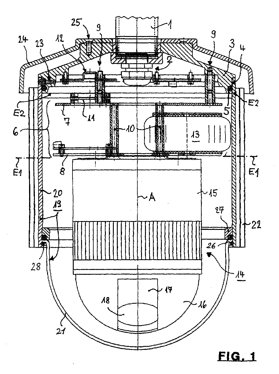
- FIG 1 the lower end of a holding tube 1 is shown through which all electrical cables for the power supply, the control and the video signals are passed through and in its further Course either straight, e.g. for ceiling mounting, or curved, e.g. for a wall mounting. That too is Attachment to any other holding surface or holding device locked in.
- a PG screw connection 2 is used for cable entry (Armored thread screw connection).
- the holding tube 1 carries a support flange 3 at its lower end an outer cylindrical surface 4, which by a groove with a sealing ring 5th is interrupted.
- a circuit board arrangement 6 on the support flange 3 attached, which in this case from an upper intermediate plate 7 (according to the Figures 8 and 9) and a lower support plate 8 (according to Figures 10 and 11) exists.
- the number of plates is not critical; it can only be one Plate or more than two plates can be used.
- the Board arrangement 6 is distributed over the circumference by several Spacers 9 with corresponding screw connections (see Figure 8) carried.
- the lower support plate 8 is on the upper intermediate plate 7 likewise with several spacer elements 10 distributed over the circumference appropriate screw connections held (see also Figure 10).
- the Spacers 10 can - as drawn - as spacers or for example, can also be designed as a cranked sheet metal angle.
- a blower 11 Above the upper intermediate plate 7 are a blower 11 and a heating element 12 arranged with which heating in a colder environment to avoid water vapor condensation.
- a network transformer 13 is arranged between the plates 7 and 8.
- the Large number of connection contacts required for the electrical connections is not shown for the sake of simplicity; it results from the Function and spatial distribution of the electrical components. In usually at least 6 contacts including the Contacts needed for the video signal.
- a commercially available dome camera 14 attached, as from different manufacturers in similar designs is delivered.
- a dome camera includes a housing 15 for accommodating a large number of electronic components and circuits.
- the horizontal rotation angle of the camera can be more than 360 °, the vertical swivel angle up to 100 °, with the - remote controlled - Actuating speed is so great that this angle in less can be run through in a second. With the automatic Chasing a moving target can change this positioning speed too be much lower.
- the invention also closes Dome cameras, which combine the optical axis of the lens can be set manually with the camera.
- the housing 15 is closed at the bottom by a dome 16, which is also referred to as "dome" in international usage becomes.
- a dome 16 which is also referred to as "dome” in international usage becomes.
- This dome 16 there is a sector-shaped viewing window 17, behind which a lens 18 of an otherwise not shown video camera is arranged.
- the dome 16, which has the shape of a hollow hemisphere, consists either entirely or partially of one for visible light and / or Infrared radiation permeable material, which is also tinted in color and / or can be mirrored.
- the lens 18 can be a Auto focus lens to use a lens with a fixed focal length or without auto focus device and / or around a remotely controllable zoom lens act. Additional functions can increase the number of connection contacts increase again.
- the dome 16 can also consist of one opaque material exist in which the viewing window 17 recessed is, in this case in the viewing window 17 a transparent material be arranged in the form of a matching sector of a spherical shell can.
- a first one is of importance for the following definitions Parting planes E1-E1 between the upper end face of the housing 15 and the underside of the lower support plate 8. It is also important that for this connection is neither an expensive bayonet connection nor a guided one Plug connection with spatially precisely assigned contacts required is like this from photo cameras and also from dome cameras is known, for which however compatible protective housings are required. A simple screw connection and / or a plug connection and / or a soldered joint is sufficient for the subject matter of the invention.
- a protective housing 19 closes at the bottom of the support flange 3 to that of an upper hollow cylindrical housing shell 20 and a second dome 21 set at the bottom, which leads to the first dome 16 is arranged at least essentially concentrically.
- the dome 21, also has the shape of a hollow hemisphere, consists of one for visible light and / or infrared radiation permeable material, the can also be tinted in color and / or mirrored.
- On its outside the housing jacket 20 is surrounded by a further jacket 22 which consists of Insulating and / or reflective material exists, but not is imperative.
- a further parting plane E2-E2 is formed, i.e. after loosening several screws 23 distributed over the circumference the protective housing 19 are completely pulled down.
- a canopy 24 is arranged, the after loosening screws 25 can be lifted up. This also makes the screws 23 accessible from the side. Alternatively, to avoid disassembly of the canopy 24 also recesses in its edge at the locations of the screws 23 be provided.
- Figure 3 shows the protective housing 19 as a removed assembly.
- the second or outer dome 21 exchangeable by means of an edge 26 folded outwards between a glued, welded or molded ring 27 and a snap ring 28 held.
- the domes 16 and 21 should at least largely concentric to each other and to the pivot and pivot point of the video camera or their optical axis can be arranged to optical distortions to keep as little as possible.
- the housing jacket 20 by a shorten or replace longer pipe section or of the pipe section cut off a partial length.
- the separability of the casing jacket 20 and dome 21 is for this and for a replacement of a damaged dome an essential requirement.
- an alternative is an adjustment also by changing the length of the spacer elements 9 and / or 10 possible.
- partial and hemispherical shell are also for the dome 16 and / or 21 not necessarily a restrictive geometric Description.
- the partial spherical shells can very well also in cylinder sections of the same diameter as that of the virtual edge, as shown in Figures 1, 3 and 12.
- the essential thing is - also in connection with the length of the housing shell 20 - that the lower edge of opaque parts does not protrude so far that the Rotation and swiveling range of the lens 18 including its Viewpoint is shadowed inadmissible.
- FIGS 4 to 7 are on the support flange 3 from below Heating element 12 and a trapezoidal distribution board 32 with a screwed semicircular cutout 33 (dashed in Figure 5 shown).
- the heating element 12 is in the plan view as a circular disk segment trained and carries in the middle a bead 34 in the rod-shaped heater 35 is housed ( Figure 4).
- the connections are omitted for simplicity. Due to the arrangement above of the blower 11 ( Figures 1, 2 and 12), the heating element by the circulated air is blown, which is thereby heated.
- the circular disc-shaped intermediate plate 7 is shown, which is screwed to the support flange 3 via the spacer elements 9 is ( Figures 1 and 2). According to FIG. 9, this is done via keyhole-shaped recesses 36, which over the screw heads 37 ( Figure 8) can be pushed. After twisting the The intermediate plate 7 can be tightened by the screw heads 37 become. At the edge of the intermediate plate 7 there are adjacent ones gap-shaped recesses 38 for hanging a safety gear, e.g. a rope loop through which all removable parts in one Be prevented from falling.
- the blower 11 is about one square recess 38 attached. Countersunk screw holes 39 serve to fasten the support plate 8 according to FIGS. 10 and 11.
- the circuit board arrangement 6a contains in this case only a single support plate 8 for holding the dome camera 14, the is only indicated by dashed lines and comes from another manufacturer. In this case there is no mains transformer because the device is connected Low voltage is supplied so that the housing jacket 20 of the protective housing 19 is designed shorter. In this case, too, the parting line lies E2-E2 above the parting plane E1-E1, so that after removal the protective housing 19, the space above the support plate 8 from the side and diagonally from below for the insertion of tools for the Establishing and releasing mechanical and electrical connections is accessible. Otherwise there is broad agreement with the Subject of Figures 1 to 3.
- the construction according to Figures 4 to 11 can easily be transferred to the construction according to FIG. 12, with the intermediate plate 7 being omitted and the support plate 8 thereof Function for attaching the dome camera 14 takes over.
- the entire arrangement in is essentially rotationally symmetrical to the axis A-A that the outer diameter of the protective housing 19 in relation to the outer diameter the dome camera 14 is as small as possible and that there is none Manipulations within the annular gap between the dome camera 14 and the protective housing 19 is required to mechanical and / or electrical Make or break connections.
- the dome camera 14 is commercially a unit from the inner dome 16 (with or without slot), the video camera itself and the attached Housing 15.
Landscapes
- Physics & Mathematics (AREA)
- General Physics & Mathematics (AREA)
- Engineering & Computer Science (AREA)
- Multimedia (AREA)
- Signal Processing (AREA)
- Studio Devices (AREA)
- Accessories Of Cameras (AREA)
Abstract
- d) die Platinenanordnung (6) an der Unterseite eines Tragflansches (3) und unterhalb von dessen Außenrand angeordnet ist und daß
- e) die zweite Kuppel (21) in Richtung der Drehachse (A-A) nach oben durch einen Gehäusemantel (20) verlängert ist, der die Platinenanordnung (6) umgreift und einen oberen Rand aufweist, der lösbar mit dem Tragflansch (3) verbunden ist, wobei an der Verbindungsstelle eine zweite Trennebene (E2-E2) gebildet ist, die oberhalb der ersten Trennebene (E1-E1) liegt.
Description
- im Gehäuse ein Drehantrieb und ein Schwenkantrieb für die ferngesteuerte Bewegung der optischen Achse des Objektivs angeordnet sind,
- der Tragflansch eine koaxiale Fläche aufweist, auf die der obere Rand des Gehäusemantels aufsetzbar ist,
- der Tragflansch im wesentlichen scheibenförmig ausgebildet ist und ein Halterohr mit dem Gehäusemantel des Schutzgehäuses verbindet,
- an der Unterseite des Tragflansches über mindestens einen Satz von Distanzelementen mindestens eine Tragplatte angeordnet ist, an der die Dome-Kamera befestigt ist, wobei die erste Trennebene zwischen der Tragplatte und der Dome-Kamera angeordnet ist,
- zwischen dem Tragflansch und der Tragplatte eine Zwischenplatte angeordnet ist, wobei die Zwischenplatte über einen ersten Satz von Distanzelementen mit dem Tragflansch und die Tragplatte über einen zweiten Satz von Distanzelementen mit der Zwischenplatte verbunden ist,
- die Platinenanordnung als Baugruppe abnehmbar am Tragflansch befestigt ist,
- die Platinenanordnung mittels schlüssellochförmiger Ausnehmungen an den Distanzelementen des Tragflansches befestigt ist,
- an dem Tragflansch ein Heizelement und an der Zwischenplatte ein Gebläse für die Umwälzung der aufgeheizten Innenatmosphäre des Schutzgehäuses angeordnet ist,
- an dem Tragflansch ein Heizelement und an der Tragplatte ein Gebläse für die Umwälzung der aufgeheizten Innenatmosphäre des Schutzgehäuses angeordnet ist,
- der Gehäusemantel an seiner Unterseite einen Ring besitzt und wenn die zweite Kuppel einen nach außen umgelegten Rand besitzt, der unter Zwischenschaltung einer Dichtung durch einen Sprengring gegen den Ring festgelegt ist,
- der Gehäusemantel von einem weiteren Mantel umgeben ist,
- über dem Tragflansch ein nach oben abnehmbares Schutzdach angeordnet ist, dessen Außenrand den oberen Rand des Schutzgehäuses übergreift,
- der Gehäusemantel des Schutzgehäuses als Hohlzylinder ausgebildet ist,
- die Länge des Gehäusemantels mindestens das 0,5-Fache, insbesondere das 0,8-Fache, seines Außendurchmessers beträgt,
- die äußere Kuppel aus einer Teilkugelschale besteht, von deren Rand in Richtung auf den Gehäusemantel ein hohlzylindrischer Fortsatz gleichen Durchmessers wie der des Randes ausgeht und/oder, wenn
- die äußere Kuppel aus einer Halbkugelschale und aus einem hohlzylindrischen Fortsatz gleichen Durchmessers besteht.
- Figur 1
- einen teilweisen Axialschnitt durch ein erstes Ausführungsbeispiel einer vollständigen Video-Kameraanordnung mit einer Dome-Kamera, einer Platinenanordnung und einem Schutzgehäuse,
- Figur 2
- eine Explosionsdarstellung des Gegenstandes nach Figur 1 mit angehobenem Schutzdach und abgenommenem Schutzgehäuse,
- Figur 3
- das abgenommene Schutzgehäuse nach Figur 1,
- Figur 4
- einen verkleinerten Axialschnitt durch den Tragflansch mit Anbauteilen,
- Figur 5
- eine Unteransicht des Gegenstandes nach Figur 4,
- Figur 6
- eine Unteransicht des Heizelements in den Figuren 4 und 5,
- Figur 7
- eine Unteransicht einer weiteren Anschlußplatine in den Figuren 4 und 5,
- Figur 8
- eine axial geschnittene Baugruppe aus dem Tragflansch und der Zwischenplatte,
- Figur 9
- eine Draufsicht auf die Zwischenplatte nach Figur 8,
- Figur 10
- eine axial geschnittene abnehmbare Baugruppe aus der Zwischenplatte und der Tragplatte mit dem Netztransformator und einer weiteren Anschlußplatine,
- Figur 11
- eine Draufsicht auf die Tragpaltte nach Figur 10, und
- Figur 12
- einen teilweisen Axialschnitt durch ein zweites Ausführungsbeispiel einer vollständigen Video-Kameraanordnung mit einer Dome-Kamera, einer Platinenanordnung und einem Schutzgehäuse, analog Figur 1.
- 1
- Halterohr
- 2
- PG-Verschraubung
- 3
- Tragflansch
- 4
- Zylinderfläche
- 5
- Dichtring
- 6
- Platinenanordnung
- 6a
- Platinenanordnung
- 7
- Zwischenplatte
- 8
- Tragplatte
- 9
- Distanzelemente
- 10
- Distanzelemente
- 11
- Gebläse
- 12
- Heizelement
- 13
- Netztransformator
- 14
- Dome-Kamera
- 15
- Gehäuse
- 16
- Kuppel
- 17
- Sichtfenster
- 18
- Objektiv
- 19
- Schutzgehäuse
- 20
- Gehäusemantel
- 21
- Kuppel
- 22
- Mantel
- 23
- Schrauben
- 24
- Schutzdach
- 25
- Schrauben
- 26
- Rand
- 27
- Ring
- 28
- Sprengring
- 29
- Rund schnurring
- 30
- Durchmesserverg rößerung
- 31
- Stufe
- 32
- Verteilerplatine
- 33
- Ausschnitt
- 34
- Sicke
- 35
- Heizkörper
- 36
- Ausnehmungen
- 37
- Schraubenköpfe
- 38
- Ausnehmungen
- 39
- Schraublöcher
- 40
- Leiterplatte
- 41
- Anschlußelemente
- A-A
- Drehachse
- E1-E1
- Trennebene
- E2-E2
- Trennebene
Claims (18)
- Video-überwachungsgerät mita) einer Dome-Kamera (14) mit einem Gehäuse (15) und einer mindestens teilweise strahlungsdurchlässigen ersten Kuppel (16), in der eine Video-Kamera mit einem Objektiv (18) angeordnet ist, dessen optische Achse um eine vertikale Drehachse (A-A) und eine horizontale Schwenkachse verstellbar ist, mitb) einer Platinenanordnung (6, 6a) mit elektrischen Bauteilen und einer Halterung für die Dome-Kamera (14), wobei zwischen der Platinenanordnung (6, 6a) und der Dome-Kamera (14) eine erste Trennebene (E1-E1) angeordnet ist, und mitc) einem Schutzgehäuse (19), das die Platinenanordnung (6, 6a) und die Dome-Kamera (14) umgibt und das im Bereich der ersten Kuppel (16) eine zweite strahlungsdurchlässige Kuppel (21) besitzt,
dadurch gekennzeichnet, daßd) die Platinenanordnung (6, 6a) an der Unterseite eines Tragflansches (3) und zumindest im wesentlichen unterhalb von dessen Außenrand angeordnet ist,e) die zweite Kuppel (21) in Richtung der Drehachse (A-A) nach oben durch einen Gehäusemantel (20) verlängert ist, der die Platinenanordnung (6, 6a) umgreift und einen oberen Rand aufweist, der lösbar mit dem Tragflansch (3) verbunden ist, wobei an der Verbindungsstelle eine zweite Trennebene (E2-E2) gebildet ist, die oberhalb der ersten Trennebene (E1-E1) liegt. - Video-überwachungsgerät nach Anspruch 1, dadurch gekennzeichnet, daß im Gehäuse (15) ein Drehantrieb und ein Schwenkantrieb für die ferngesteuerte Bewegung der optischen Achse des Objektivs (18) angeordnet sind.
- Video-überwachungsgerät nach Anspruch 1, dadurch gekennzeichnet, daß der Tragflansch (3) eine koaxiale Fläche (4) aufweist, auf die der obere Rand des Gehäusemantels (20) aufsetzbar ist.
- Video-überwachungsgerät nach Anspruch 1, dadurch gekennzeichnet, daß der Tragflansch (3) im wesentlichen scheibenförmig ausgebildet ist und ein Halterohr (1) mit dem Gehäusemantel (20) des Schutzgehäuses (19) verbindet.
- Video-überwachungsgerät nach Anspruch 1, dadurch gekennzeichnet, daß an der Unterseite des Tragflansches (3) über mindestens einen Satz von Distanzelementen (9, 10) mindestens eine Tragplatte (8) angeordnet ist, an der die Dome-Kamera (14) befestigt ist, wobei die erste Trennebene (E1-E1) zwischen der Tragplatte (8) und der Dome-Kamera (14) angeordnet ist.
- Video-überwachungsgerät nach Anspruch 5, dadurch gekennzeichnet, daß zwischen dem Tragflansch (3) und der Tragplatte (8) eine Zwischenplatte (7) angeordnet ist, wobei die Zwischenplatte (7) über einen ersten Satz von Distanzelementen (9) mit dem Tragflansch (3) und die Tragplatte (8) über einen zweiten Satz von Distanzelementen (10) mit der Zwischenplatte (7) verbunden ist.
- Video-überwachungsgerät nach einem der Ansprüche 5 und 6, dadurch gekennzeichnet, daß die Platinenanordnung (6, 6a) als Baugruppe abnehmbar am Tragflansch (3) befestigt ist.
- Video-überwachungsgerät nach Anspruch 7, dadurch gekennzeichnet, daß die Platinenanordnung (6, 6a) mittels schlüssellochförmiger Ausnehmungen (36) an den Distanzelementen (9) des Tragflansches befestigt ist.
- Video-überwachungsgerät nach Anspruch 6, dadurch gekennzeichnet, daß an dem Tragflansch (3) ein Heizelement (12) und an der Zwischenplatte (7) ein Gebläse (11) für die Umwälzung der aufgeheizten Innenatmosphäre des Schutzgehäuses (19) angeordnet ist.
- Video-überwachungsgerät nach Anspruch 5, dadurch gekennzeichnet, daß an dem Tragflansch (3) ein Heizelement (12) und an der Tragplatte (8) ein Gebläse (11) für die Umwälzung der aufgeheizten Innenatmosphäre des Schutzgehäuses (19) angeordnet ist.
- Video-überwachungsgerät nach Anspruch 1, dadurch gekennzeichnet, daß der Gehäusemantel (20) an seiner Unterseite einen Ring (27) besitzt und daß die zweite Kuppel (21) einen nach außen umgelegten Rand (26) besitzt, der unter Zwischenschaltung einer Dichtung (29) durch einen Sprengring (28) gegen den Ring (27) festgelegt ist.
- Video-überwachungsgerät nach Anspruch 1, dadurch gekennzeichnet, daß der Gehäusemantel (20) von einem weiteren Mantel (22) umgeben ist.
- Video-überwachungsgerät nach Anspruch 1, dadurch gekennzeichnet, daß über dem Tragflansch (3) ein nach oben abnehmbares Schutzdach (24) angeordnet ist, dessen Außenrand den oberen Rand des Schutzgehäuses (19) übergreift.
- Video-überwachungsgerät nach Anspruch 1, dadurch gekennzeichnet, daß der Gehäusemantel (20) des Schutzgehäuses (19) als Hohlzylinder ausgebildet ist.
- Video-überwachungsgerät nach Anspruch 14, dadurch gekennzeichnet, daß die Länge des Gehäusemantels (20) mindestens das 0,5-Fache seines Außendurchmessers beträgt.
- Video-überwachungsgerät nach Anspruch 15, dadurch gekennzeichnet, daß die Länge des Gehäusemantels (20) mindestens das 0,8-Fache seines Außendurchmessers beträgt.
- Video-überwachungsgerät nach Anspruch 1, dadurch gekennzeichnet, daß die äußere Kuppel (21) aus einer Teilkugelschale besteht, von deren Rand in Richtung auf den Gehäusemantel (20) ein hohlzylindrischer Fortsatz gleichen Durchmessers wie der des Randes ausgeht.
- Video-überwachungsgerät nach Anspruch 17, dadurch gekennzeichnet, daß die äußere Kuppel (21) aus einer Halbkugelschale und aus einem hohlzylindrischen Fortsatz gleichen Durchmessers besteht.
Applications Claiming Priority (2)
| Application Number | Priority Date | Filing Date | Title |
|---|---|---|---|
| DE10013780A DE10013780C1 (de) | 2000-03-20 | 2000-03-20 | Video-Überwachungsgerät mit einer Dome-Kamera und einem Schutzgehäuse |
| DE10013780 | 2000-03-20 |
Publications (2)
| Publication Number | Publication Date |
|---|---|
| EP1136964A2 true EP1136964A2 (de) | 2001-09-26 |
| EP1136964A3 EP1136964A3 (de) | 2002-05-29 |
Family
ID=7635634
Family Applications (1)
| Application Number | Title | Priority Date | Filing Date |
|---|---|---|---|
| EP01100198A Withdrawn EP1136964A3 (de) | 2000-03-20 | 2001-01-18 | Video-Überwachungsgerät mit einer Dome-Kamera und einem Schutzgehäuse |
Country Status (3)
| Country | Link |
|---|---|
| US (1) | US20010022627A1 (de) |
| EP (1) | EP1136964A3 (de) |
| DE (1) | DE10013780C1 (de) |
Cited By (2)
| Publication number | Priority date | Publication date | Assignee | Title |
|---|---|---|---|---|
| NL1024286C2 (nl) * | 2003-09-12 | 2005-03-15 | Bosch Gmbh Robert | Waarneeminrichting. |
| US7306383B2 (en) | 2004-07-27 | 2007-12-11 | Robert Bosch Gmbh | Compound dome window for a surveillance camera |
Families Citing this family (75)
| Publication number | Priority date | Publication date | Assignee | Title |
|---|---|---|---|---|
| US20020140848A1 (en) * | 2001-03-30 | 2002-10-03 | Pelco | Controllable sealed chamber for surveillance camera |
| FR2842638B1 (fr) * | 2002-07-19 | 2005-05-06 | Abdulai Danso | Systeme pour l'enseignement a distance ainsi que l'installation pour la mise en oeuvre dudit systeme |
| US8154581B2 (en) | 2002-10-15 | 2012-04-10 | Revolutionary Concepts, Inc. | Audio-video communication system for receiving person at entrance |
| JP3726817B2 (ja) * | 2003-03-03 | 2005-12-14 | ソニー株式会社 | 撮像装置 |
| US20040223062A1 (en) * | 2003-05-05 | 2004-11-11 | Richard Pettegrew | Pan and tilt camera system |
| FR2858159B1 (fr) * | 2003-07-23 | 2005-11-25 | Hymatom | Ensemble pour la protection d'une camera mobile |
| JP2005063560A (ja) * | 2003-08-12 | 2005-03-10 | Sony Corp | ディスク記録及び/又は再生装置 |
| US8553113B2 (en) * | 2003-08-20 | 2013-10-08 | At&T Intellectual Property I, L.P. | Digital image capturing system and method |
| US7699691B1 (en) * | 2005-05-11 | 2010-04-20 | L-3 Communications Sonoma Eo, Inc. | Cooling system and method for enclosed volume |
| US20070126872A1 (en) * | 2005-12-06 | 2007-06-07 | Michael Bolotine | Modular surveillance camera system |
| US20070126871A1 (en) * | 2005-12-06 | 2007-06-07 | Henninger Paul E Iii | Modular surveillance camera system with self-identification capability |
| JP4771827B2 (ja) * | 2006-02-21 | 2011-09-14 | 三洋電機株式会社 | 監視カメラ |
| EP1883226A3 (de) | 2006-07-28 | 2008-05-07 | Videotec S.P.A. | Gehäuse für CCTV-Kamera |
| ATE524799T1 (de) * | 2006-10-10 | 2011-09-15 | Axis Ab | Überwachungskamera |
| US8174573B2 (en) * | 2008-09-05 | 2012-05-08 | Vtc Electronics Corporation | Monitoring camera |
| US7762731B2 (en) * | 2008-09-12 | 2010-07-27 | Pelco, Inc. | Environmentally sealed enclosure |
| GB0920036D0 (en) * | 2009-11-16 | 2009-12-30 | Vector Developments Ltd | An imaging device, a related system and method of fabrication |
| US8385065B2 (en) * | 2010-01-19 | 2013-02-26 | Flir Systems, Inc. | Gimbal system with forced flow of external air through a channel to remove heat |
| KR101304420B1 (ko) * | 2011-07-26 | 2013-09-05 | 삼성중공업 주식회사 | 슬로싱 억제 장치 관찰용 모니터링 장치 |
| TWI448150B (zh) * | 2011-08-02 | 2014-08-01 | Qisda Corp | 具有散熱功能之影像監視模組 |
| US9485395B2 (en) * | 2011-10-19 | 2016-11-01 | Epilog Imaging Systems | Compound dome camera assembly |
| CN102809875B (zh) * | 2012-07-30 | 2015-04-22 | 深圳丰泰达电子有限公司 | 一种球型安防监控装置的密封结构 |
| US9380190B2 (en) * | 2012-08-06 | 2016-06-28 | Gentex Corporation | Rotating lens apparatus |
| US20140130375A1 (en) | 2012-11-15 | 2014-05-15 | Nike, Inc. | Article Of Footwear Incorporating A Knitted Component |
| US9332163B2 (en) | 2013-04-10 | 2016-05-03 | Sensormatic Electronics, LLC | Indoor bubble adapter |
| US10440165B2 (en) | 2013-07-26 | 2019-10-08 | SkyBell Technologies, Inc. | Doorbell communication and electrical systems |
| US10044519B2 (en) | 2015-01-05 | 2018-08-07 | SkyBell Technologies, Inc. | Doorbell communication systems and methods |
| US10708404B2 (en) | 2014-09-01 | 2020-07-07 | Skybell Technologies Ip, Llc | Doorbell communication and electrical systems |
| US11004312B2 (en) | 2015-06-23 | 2021-05-11 | Skybell Technologies Ip, Llc | Doorbell communities |
| US9237318B2 (en) * | 2013-07-26 | 2016-01-12 | SkyBell Technologies, Inc. | Doorbell communication systems and methods |
| US10204467B2 (en) | 2013-07-26 | 2019-02-12 | SkyBell Technologies, Inc. | Smart lock systems and methods |
| US9142214B2 (en) | 2013-07-26 | 2015-09-22 | SkyBell Technologies, Inc. | Light socket cameras |
| US11889009B2 (en) | 2013-07-26 | 2024-01-30 | Skybell Technologies Ip, Llc | Doorbell communication and electrical systems |
| US11764990B2 (en) | 2013-07-26 | 2023-09-19 | Skybell Technologies Ip, Llc | Doorbell communications systems and methods |
| US11651665B2 (en) | 2013-07-26 | 2023-05-16 | Skybell Technologies Ip, Llc | Doorbell communities |
| US10733823B2 (en) | 2013-07-26 | 2020-08-04 | Skybell Technologies Ip, Llc | Garage door communication systems and methods |
| US11909549B2 (en) | 2013-07-26 | 2024-02-20 | Skybell Technologies Ip, Llc | Doorbell communication systems and methods |
| US9736284B2 (en) | 2013-07-26 | 2017-08-15 | SkyBell Technologies, Inc. | Doorbell communication and electrical systems |
| US20170263067A1 (en) | 2014-08-27 | 2017-09-14 | SkyBell Technologies, Inc. | Smart lock systems and methods |
| US20180343141A1 (en) | 2015-09-22 | 2018-11-29 | SkyBell Technologies, Inc. | Doorbell communication systems and methods |
| US9769435B2 (en) | 2014-08-11 | 2017-09-19 | SkyBell Technologies, Inc. | Monitoring systems and methods |
| US10672238B2 (en) | 2015-06-23 | 2020-06-02 | SkyBell Technologies, Inc. | Doorbell communities |
| US9799183B2 (en) | 2013-12-06 | 2017-10-24 | SkyBell Technologies, Inc. | Doorbell package detection systems and methods |
| US9786133B2 (en) | 2013-12-06 | 2017-10-10 | SkyBell Technologies, Inc. | Doorbell chime systems and methods |
| US9743049B2 (en) | 2013-12-06 | 2017-08-22 | SkyBell Technologies, Inc. | Doorbell communication systems and methods |
| US20170085843A1 (en) | 2015-09-22 | 2017-03-23 | SkyBell Technologies, Inc. | Doorbell communication systems and methods |
| US12155974B2 (en) | 2014-06-23 | 2024-11-26 | Skybell Technologies Ip, Llc | Doorbell communication systems and methods |
| US11184589B2 (en) | 2014-06-23 | 2021-11-23 | Skybell Technologies Ip, Llc | Doorbell communication systems and methods |
| US9888216B2 (en) | 2015-09-22 | 2018-02-06 | SkyBell Technologies, Inc. | Doorbell communication systems and methods |
| US10687029B2 (en) | 2015-09-22 | 2020-06-16 | SkyBell Technologies, Inc. | Doorbell communication systems and methods |
| US9997036B2 (en) | 2015-02-17 | 2018-06-12 | SkyBell Technologies, Inc. | Power outlet cameras |
| US9305446B1 (en) * | 2014-10-16 | 2016-04-05 | Clinton Electronics Corporation | Security camera with internal sealing arrangement |
| US11575537B2 (en) | 2015-03-27 | 2023-02-07 | Skybell Technologies Ip, Llc | Doorbell communication systems and methods |
| US10742938B2 (en) | 2015-03-07 | 2020-08-11 | Skybell Technologies Ip, Llc | Garage door communication systems and methods |
| EP3275172B1 (de) * | 2015-03-24 | 2021-12-15 | Battelle Memorial Institute | Bilderzeugungssystem und verfahren zur erzeugung von bildern |
| US11381686B2 (en) | 2015-04-13 | 2022-07-05 | Skybell Technologies Ip, Llc | Power outlet cameras |
| US11641452B2 (en) | 2015-05-08 | 2023-05-02 | Skybell Technologies Ip, Llc | Doorbell communication systems and methods |
| US20180047269A1 (en) | 2015-06-23 | 2018-02-15 | SkyBell Technologies, Inc. | Doorbell communities |
| US10706702B2 (en) | 2015-07-30 | 2020-07-07 | Skybell Technologies Ip, Llc | Doorbell package detection systems and methods |
| US12236774B2 (en) | 2015-09-22 | 2025-02-25 | Skybell Technologies Ip, Llc | Doorbell communication systems and methods |
| US10043332B2 (en) | 2016-05-27 | 2018-08-07 | SkyBell Technologies, Inc. | Doorbell package detection systems and methods |
| US10582095B2 (en) | 2016-10-14 | 2020-03-03 | MP High Tech Solutions Pty Ltd | Imaging apparatuses and enclosures |
| US11765323B2 (en) | 2017-05-26 | 2023-09-19 | Calumino Pty Ltd. | Apparatus and method of location determination in a thermal imaging system |
| US10909825B2 (en) | 2017-09-18 | 2021-02-02 | Skybell Technologies Ip, Llc | Outdoor security systems and methods |
| EP3762909A1 (de) * | 2018-05-28 | 2021-01-13 | Greenwave Systems PTE. LTD. | Bereichsüberwachung und kommunikation |
| KR102238152B1 (ko) | 2019-01-25 | 2021-04-09 | 한화테크윈 주식회사 | 카메라 장치 |
| DE102019122373B3 (de) * | 2019-08-20 | 2020-12-10 | Dallmeier Electronic Gmbh & Co. Kg | Halteanordnung und Verfahren zur hängenden Montage eines Objekts, insbesondere einer Überwachungskamera |
| JP2022545039A (ja) | 2019-08-24 | 2022-10-24 | スカイベル テクノロジーズ アイピー、エルエルシー | ドアベル通信システム及び方法 |
| EP3799002A1 (de) * | 2019-09-26 | 2021-03-31 | Axis AB | Dome-kamera mit zwei köpfen |
| CN114006294B (zh) * | 2021-10-29 | 2024-04-09 | 深圳供电局有限公司 | 一种电力变压器安全操作设备 |
| CN114333223B (zh) * | 2021-12-22 | 2022-08-09 | 温州理工学院 | 一种车间厂房用火灾预防监控装置及其使用方法 |
| USD1101014S1 (en) | 2023-05-08 | 2025-11-04 | Lsi Industries, Inc. | Infrared sensor lens |
| USD1101831S1 (en) | 2023-05-08 | 2025-11-11 | Lsi Industries, Inc. | Infrared sensor lens |
| USD1061289S1 (en) | 2023-05-08 | 2025-02-11 | Lsi Industries, Inc. | Infrared sensor lens |
| USD1061288S1 (en) | 2023-05-08 | 2025-02-11 | Lsi Industries, Inc. | Infrared sensor lens |
Family Cites Families (11)
| Publication number | Priority date | Publication date | Assignee | Title |
|---|---|---|---|---|
| US3819856A (en) * | 1972-04-17 | 1974-06-25 | D Pearl | Camera capsule |
| US4920367A (en) * | 1987-06-22 | 1990-04-24 | Pagano Raymond V | Ballistic rated camera housing and method for forming |
| US4764008A (en) * | 1987-11-19 | 1988-08-16 | Wren Clifford T | Surveillance housing assembly |
| WO1992010063A1 (en) * | 1990-11-21 | 1992-06-11 | Trafalgar Security Pty. Ltd. | Surveillance systems |
| US5418567A (en) * | 1993-01-29 | 1995-05-23 | Bayport Controls, Inc. | Surveillance camera system |
| US5394184A (en) * | 1993-08-30 | 1995-02-28 | Sensormatic Electronics Corporation | Surveillance assembly having circumferential delivery of forced air to viewing bubble |
| US5689304A (en) * | 1996-03-04 | 1997-11-18 | Philips Electronic North America Corporation | Indoor/outdoor surveillance housing |
| JPH11215405A (ja) * | 1998-01-26 | 1999-08-06 | Matsushita Electric Ind Co Ltd | 部品実装部材および部品実装方法 |
| US6234691B1 (en) * | 1998-06-15 | 2001-05-22 | Philips Electronics North America Corporation | Apparatus for mounting a surveillance camera |
| US6061087A (en) * | 1998-07-16 | 2000-05-09 | Sensormatic Electronics Corporation | Outdoor enclosure for video surveillance system |
| US6354749B1 (en) * | 1998-09-09 | 2002-03-12 | Videolarm, Inc. | Housing for surveillance camera |
-
2000
- 2000-03-20 DE DE10013780A patent/DE10013780C1/de not_active Expired - Fee Related
-
2001
- 2001-01-18 EP EP01100198A patent/EP1136964A3/de not_active Withdrawn
- 2001-01-24 US US09/768,752 patent/US20010022627A1/en not_active Abandoned
Cited By (4)
| Publication number | Priority date | Publication date | Assignee | Title |
|---|---|---|---|---|
| NL1024286C2 (nl) * | 2003-09-12 | 2005-03-15 | Bosch Gmbh Robert | Waarneeminrichting. |
| EP1515288A1 (de) | 2003-09-12 | 2005-03-16 | Robert Bosch GmbH | Beobachtungssystem. |
| US7372645B2 (en) | 2003-09-12 | 2008-05-13 | Robert Bosch Gmbh | Observation device |
| US7306383B2 (en) | 2004-07-27 | 2007-12-11 | Robert Bosch Gmbh | Compound dome window for a surveillance camera |
Also Published As
| Publication number | Publication date |
|---|---|
| EP1136964A3 (de) | 2002-05-29 |
| US20010022627A1 (en) | 2001-09-20 |
| DE10013780C1 (de) | 2001-05-23 |
Similar Documents
| Publication | Publication Date | Title |
|---|---|---|
| DE10013780C1 (de) | Video-Überwachungsgerät mit einer Dome-Kamera und einem Schutzgehäuse | |
| EP2689227B1 (de) | Hebeeinheit für rohrinspektionssysteme | |
| DE69232405T2 (de) | Überwachungsvorrichtung mit Fernsehkamera und schwenkbar angeordneter Aufhängung | |
| DE102007048349A1 (de) | Leuchtenanschlusskasten | |
| DE29703350U1 (de) | Innen- und Außenüberwachungsgehäuse | |
| DE60010207T2 (de) | Umweltumhüllung | |
| WO2010058000A1 (de) | Mehrfunktionales versorgungselement | |
| DE202005021536U1 (de) | Sensorleuchte | |
| EP0323621B1 (de) | Strahlungsempfindlicher Schalter | |
| EP0668694A2 (de) | Schutzgehäuse für optische Geräte mit vereinfachtem elektrischen Anschluss | |
| EP1441317A1 (de) | Kamera, insbesondere Video-Überwachungskamera | |
| DE4027347C2 (de) | ||
| EP2564268B1 (de) | System mit blitzlichtreflektorarm zur befestigung an einem fotoapparat oder einer kamera | |
| DE102014000582A1 (de) | Licht aussendende Einrichtung | |
| DE102017121835A1 (de) | Zwischenstück für Mastleuchte | |
| DE102008022357B4 (de) | Leuchte, insbesondere Decken- oder Wandleuchte | |
| DE69924180T2 (de) | Heizgerät | |
| EP4630727A1 (de) | Operationsleuchte | |
| DE19705404A1 (de) | Schutzgehäuse für optische Geräte mit einem Haltekörper zum Anbringen an einer Befestigungsfläche | |
| EP0442338A1 (de) | Optische Ueberwachungseinrichtung | |
| DE9107452U1 (de) | Vorrichtung zur Feuerüberwachung, insbesondere in Waldgebieten | |
| DE4311804A1 (de) | Energiesparlampe | |
| DE202012104249U1 (de) | Lampenfassungskamera | |
| DE19951348A1 (de) | Anzeigevorrichtung | |
| EP0014839A1 (de) | Vorrichtung zum Keimfreimachen der Luft, unter Verwendung eines vertikal angeordneten stabförmigen UV-Strahlers |
Legal Events
| Date | Code | Title | Description |
|---|---|---|---|
| PUAI | Public reference made under article 153(3) epc to a published international application that has entered the european phase |
Free format text: ORIGINAL CODE: 0009012 |
|
| AK | Designated contracting states |
Kind code of ref document: A2 Designated state(s): AT BE CH CY DE DK ES FI FR GB GR IE IT LI LU MC NL PT SE TR |
|
| AX | Request for extension of the european patent |
Free format text: AL;LT;LV;MK;RO;SI |
|
| PUAL | Search report despatched |
Free format text: ORIGINAL CODE: 0009013 |
|
| AK | Designated contracting states |
Kind code of ref document: A3 Designated state(s): AT BE CH CY DE DK ES FI FR GB GR IE IT LI LU MC NL PT SE TR |
|
| AX | Request for extension of the european patent |
Free format text: AL;LT;LV;MK;RO;SI |
|
| RIC1 | Information provided on ipc code assigned before grant |
Free format text: 7G 08B 13/196 A, 7G 08B 15/00 B, 7H 04N 5/225 B, 7G 03B 17/08 B |
|
| AKX | Designation fees paid | ||
| REG | Reference to a national code |
Ref country code: DE Ref legal event code: 8566 |
|
| STAA | Information on the status of an ep patent application or granted ep patent |
Free format text: STATUS: THE APPLICATION IS DEEMED TO BE WITHDRAWN |
|
| 18D | Application deemed to be withdrawn |
Effective date: 20021130 |