EP1137023A2 - Hängeschalteinrichtung zum Steuern eines antreibbaren Hebezeugs - Google Patents
Hängeschalteinrichtung zum Steuern eines antreibbaren Hebezeugs Download PDFInfo
- Publication number
- EP1137023A2 EP1137023A2 EP01250088A EP01250088A EP1137023A2 EP 1137023 A2 EP1137023 A2 EP 1137023A2 EP 01250088 A EP01250088 A EP 01250088A EP 01250088 A EP01250088 A EP 01250088A EP 1137023 A2 EP1137023 A2 EP 1137023A2
- Authority
- EP
- European Patent Office
- Prior art keywords
- housing
- receiving element
- control
- handle
- power controller
- Prior art date
- Legal status (The legal status is an assumption and is not a legal conclusion. Google has not performed a legal analysis and makes no representation as to the accuracy of the status listed.)
- Granted
Links
Images

Classifications
-
- H—ELECTRICITY
- H01—ELECTRIC ELEMENTS
- H01H—ELECTRIC SWITCHES; RELAYS; SELECTORS; EMERGENCY PROTECTIVE DEVICES
- H01H9/00—Details of switching devices, not covered by groups H01H1/00 - H01H7/00
- H01H9/02—Bases, casings, or covers
- H01H9/0214—Hand-held casings
- H01H9/0235—Hand-held casings specially adapted for remote control, e.g. of audio or video apparatus
Definitions
- the invention relates to a pendant switching device for controlling a drivable Hoist, which is a lifting and lowering, attached to a load-bearing device according to the preamble of claim 1.
- a hanging switch device which for controlling a Hanging crane is used.
- the pendant switch is provided with a housing in which Control elements in the form of switches are arranged by means of outside accessible buttons can be operated by an operator. The actuation causes Control signals that are used to move the overhead crane.
- the housing is over one Rope connected to the overhead crane. There is a separate electrical cable on the rope, via which the control signals are routed to the overhead crane.
- Another paddle switching device is known from EP 592 795. She also decreed via a housing in which control elements are present, which are operated by push buttons can be operated. At the top of the case, this is about a Cable with a central strain relief rope with a hoist and its Control connected.
- the upper housing section has a plug that is connected to the cable can be connected via a quick coupling. The upper housing section also serves to touch and retract the pendant control.
- the known retractable pendant control devices have the disadvantage that the Operator freedom of movement due to the length of the connecting cable is restricted relative to the hoist.
- the object of the invention is to provide a universal switching device propose which freedom of movement no longer restricts the operator.
- the solution provides for the housing to be coupled into the receiving element can be plugged in and pulled out again for uncoupling and that in and / or on the housing a transmitter for wireless transmission of the control signals one arranged away from the housing, with the power controller in terms of control technology connected receiver, and a power supply for the control elements and the transmitter are provided.
- the toggle switch device is due to the wireless transmission the control signals can be uncoupled easily from the receiving element, so that a Operator controls the hoist regardless of the length of the Can control connection cable.
- An embodiment of the invention sees a Receiving element arranged handle to pull the hoist across the To be able to move the stroke direction.
- a particularly advantageous embodiment of the Receiving element provides that this itself is designed as a handle.
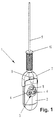
- Fig. 1 shows a pendant switching device 1 for remote control of a not shown drivable hoist, which can be lifted and lowered in a known manner, at one Has suspension means attached load suspension.
- the pendant switching device has arranged in an elongated housing 2 Probe elements 3 as control elements, which are actuated from the outside 4, 5 can be operated by an operator.
- the control elements 3 give electrical control signals for a power controller of the hoist drive when actuated (not shown).
- the hoist drive can be one Actuate drive as well as a linear actuator.
- At the top of the hoist frame is a downward traction device 6 attached, which at its lower end Receiving element 7 in the form of an injection molded half-shell open at the bottom wearing.
- the opening of the receiving element 7 is complementary to the upper part of the elongated housing 2 formed and with locking elements 8 (see FIG. 2) Mistake.
- the Locking elements 8 are made in the housing 2 arranged depressions and from corresponding projections in the Receiving element 7 formed.
- the control signals for the power controller are arranged in the housing 2 Wirelessly transmit infrared transmitter to a corresponding infrared receiver, which can be arranged, for example, directly on the power controllers and is technically connectable with these. Also located in the Housing 2 a (not shown) power supply for the control elements 3 and the transmitter. Of the transmitter in Fig. 1 and 2, only the exit window 9 for the See infrared transmission signal.
- FIG. 1 and 2 further show a handle 10 formed as a hollow cylinder made of plastic, through which the slack pull rope 6 is passed longitudinally and on the pull rope 6 can be moved lengthways.
- a handle 10 formed as a hollow cylinder made of plastic, through which the slack pull rope 6 is passed longitudinally and on the pull rope 6 can be moved lengthways.
- the handle 10 and the pull rope 6 the hoist moves across the direction of the stroke by pulling, which is common is desirable.
- the lower end of the handle is supported on the upper end of the receiving element 7.
- the receiving element is also conceivable 7 train yourself as a handle.
Landscapes
- Engineering & Computer Science (AREA)
- Multimedia (AREA)
- Control And Safety Of Cranes (AREA)
- Jib Cranes (AREA)
- Load-Engaging Elements For Cranes (AREA)
- Carriers, Traveling Bodies, And Overhead Traveling Cranes (AREA)
Abstract
Description
- Fig. 1
- eine Hängeschalteinrichtung zum Fernsteuern mit Steuerungselementen und einem Sender und
- Fig. 2
- die Hängeschalteinrichtung gemäß Fig. 1 mit abgekuppeltem Gehäuse.
- 1
- Hängeschalteinrichtung
- 2
- Gehäuse
- 3
- Tastelement
- 4
- Betätigungselement
- 5
- Betätigungselement
- 6
- Zugmittel
- 7
- Aufnahmeelement
- 8
- Rastelement
- 9
- Austrittsfenster
- 10
- Griff
Claims (8)
- Hängeschalteinrichtung zum Steuern eines antreibbaren Hebezeugs, das ein heb- und senkbares, an einem Tragmittel befestigtes Lastaufnahmemittel aufweist,dadurch gekennzeichnet,mit Steuerungselementen, die in einem Gehäuse angeordnet, von außen mittels Betätigungselementen bedienbar und mit einem Leistungssteller des Antriebs steuerungstechnisch verbindbar sind und die bei Betätigung elektrische Steuersignale für den Leistungssteller abgeben,mit einem am Hebezeug befestigten nach unten geführten Zugmittel und einem an dessen unterem Ende angeordneten Aufnahmeelement, an das der obere Abschnitt des Gehäuses lösbar ankuppelbar ist,dass das Gehäuse (2) zum Ankuppeln in das Aufnahmeelement (7) verrastend einsteckbar und zum Abkuppeln wieder herausziehbar ist und dass im und/oder am Gehäuse (2) ein Sender zur drahtlosen Übertragung der Steuersignale an einen vom Gehäuse (2) entfernt angeordneten, mit dem Leistungssteller steuerungstechnisch verbundenen Empfänger, undeine Stromversorgung für die Steuerungselemente und den Sender vorgesehen sind.
- Hängeschalteinrichtung nach Anspruch 1,
dadurch gekennzeichnet, dass am Aufnahmeelement (7) ein Griff (10) zum Ziehen des verfahrbaren Hebezeugs quer zur Hubrichtung vorgesehen ist. - Hängeschalteinrichtung nach Anspruch 2,
dadurch gekennzeichnet, dass der Griff (10) als Hohlzylinder ausgebildet und das Zugseil bei frei verschiebbarem Griff (10) durch diesen längs hindurchgeführt ist. - Hängeschalteinrichtung nach einem der Ansprüche 2 oder 3,
dadurch gekennzeichnet, dass sich der Griff (10) beim Ziehen stirnseitig an der oberen Stirnseite des Aufnahmeelements (7) abstützt. - Hängeschalteinrichtung nach einem der vorhergehenden Ansprüche,
dadurch gekennzeichnet, dass das Aufnahmeelement (7) als eine nach unten offene Halbschale ausgebildet ist. - Hängeschalteinrichtung nach einem der vorhergehenden Ansprüche,
dadurch gekennzeichnet, dass das Aufnahmeelement (7) selbst als Griff (10) zum Ziehen des verfahrbaren Hebezeugs durch eine Bedienperson ausgebildet ist. - Hängeschalteinrichtung nach einem der vorhergehenden Ansprüche,
dadurch gekennzeichnet, dass ein Rastmechanismus vorgesehen ist, wobei am Gehäuse (2) Vertiefungen oder Vorsprünge und am Aufnahmeelement (7) korrespondierende Vorsprünge bzw. Vertiefungen angeordnet sind. - Hängeschalteinrichtung nach einem der vorhergehenden Ansprüche,
dadurch gekennzeichnet, dass das Zugmittel (6) ein biegeschlaffes Seil ist.
Applications Claiming Priority (2)
| Application Number | Priority Date | Filing Date | Title |
|---|---|---|---|
| DE10014904 | 2000-03-17 | ||
| DE10014904 | 2000-03-17 |
Publications (3)
| Publication Number | Publication Date |
|---|---|
| EP1137023A2 true EP1137023A2 (de) | 2001-09-26 |
| EP1137023A3 EP1137023A3 (de) | 2003-06-04 |
| EP1137023B1 EP1137023B1 (de) | 2006-09-13 |
Family
ID=7636369
Family Applications (1)
| Application Number | Title | Priority Date | Filing Date |
|---|---|---|---|
| EP01250088A Expired - Lifetime EP1137023B1 (de) | 2000-03-17 | 2001-03-14 | Hängeschalteinrichtung zum Steuern eines antreibbaren Hebezeugs |
Country Status (4)
| Country | Link |
|---|---|
| US (1) | US6525282B2 (de) |
| EP (1) | EP1137023B1 (de) |
| AT (1) | ATE339771T1 (de) |
| DE (2) | DE10111102A1 (de) |
Families Citing this family (20)
| Publication number | Priority date | Publication date | Assignee | Title |
|---|---|---|---|---|
| DE20211542U1 (de) * | 2002-07-10 | 2003-01-16 | Demag Cranes & Components GmbH, 58300 Wetter | Hängesteuereinrichtung |
| DE20216079U1 (de) * | 2002-07-10 | 2003-03-13 | Demag Cranes & Components GmbH, 58300 Wetter | Hängesteuereinrichtung |
| WO2006015267A2 (en) * | 2004-07-29 | 2006-02-09 | Unovo Inc. | Hoist with detachable power and control unit |
| GB0423194D0 (en) * | 2004-10-19 | 2004-11-24 | Racal Acoustics Ltd | Attachment apparatus |
| US7323646B2 (en) * | 2005-04-14 | 2008-01-29 | Conntrol International, Inc. | Hand and foot switch |
| USD530680S1 (en) * | 2005-06-21 | 2006-10-24 | Biocare Systems, Inc. | Control module for heat and light therapy device |
| USD552562S1 (en) * | 2005-09-28 | 2007-10-09 | Kito Corporation | Pendant switch for controlling a hoist |
| DE102006044600A1 (de) * | 2006-09-19 | 2008-03-27 | Stahl Cranesystems Gmbh | Kran mit angebundener drahtloser Steuerbox |
| US8822884B2 (en) * | 2007-08-07 | 2014-09-02 | Lincoln Global, Inc. | Welding apparatus providing auxiliary power |
| ES2362986T3 (es) * | 2007-09-25 | 2011-07-18 | Ebl Systems Aktiebolag | Un dispositivo de elevación. |
| USD609699S1 (en) | 2008-06-04 | 2010-02-09 | Racal Acoustics Limited | Ear piece |
| AU324191S (en) | 2008-06-04 | 2009-01-23 | Racal Acoustics Ltd | Ear pieces |
| USD668424S1 (en) * | 2010-07-20 | 2012-10-02 | Ilcon Gmbh | Patient hoist controller |
| USD667380S1 (en) * | 2010-11-25 | 2012-09-18 | Kito Corporation | Switch for hoist |
| DE102011050111B4 (de) | 2011-05-04 | 2017-09-07 | Terex Mhps Gmbh | Park- und Ladestation für einen drahtlosen Steuerschalter eines Hebezeugs |
| USD715230S1 (en) * | 2013-05-07 | 2014-10-14 | Konecranes Plc | Pendant control |
| USD714739S1 (en) * | 2013-09-06 | 2014-10-07 | Konecranes Plc | Pendant control |
| RU188257U1 (ru) * | 2017-06-26 | 2019-04-04 | Акционерное общество "Федеральный научно-производственный центр "Нижегородский научно-исследовательский институт радиотехники" | Выносной пульт управления приводом подъёмно-мачтового устройства |
| USD867309S1 (en) * | 2018-06-29 | 2019-11-19 | J.D. Neuhaus Holding Gmbh & Co. Kg | Hand control |
| RU201013U1 (ru) * | 2019-07-09 | 2020-11-23 | Акционерное общество научно-внедренческое предприятие "ПРОТЕК" | Пульт контроля и управления |
Family Cites Families (9)
| Publication number | Priority date | Publication date | Assignee | Title |
|---|---|---|---|---|
| US2791665A (en) | 1954-04-15 | 1957-05-07 | Emil A Baumbach | Switch with cushioning protective housing |
| US3654415A (en) * | 1970-09-24 | 1972-04-04 | Columbus Mckinnon Corp | Pendant hoist control device |
| DE2227364A1 (de) * | 1972-06-06 | 1973-12-20 | Huels Chemische Werke Ag | Mittel zur reinigung von abwaessern |
| US4520247A (en) * | 1984-03-05 | 1985-05-28 | Columbus Mckinnon Corporation | Pendant type electrical switching device |
| DE59106596D1 (de) * | 1991-04-17 | 1995-11-02 | Abus Kransysteme Gmbh & Co Kg | Hängetaster zum Steuern von Hebezeugen und/oder Krananlagen. |
| DE4234542A1 (de) | 1992-10-14 | 1994-04-21 | Buehne Werner Abus Kg | Hängetaster |
| FI96304C (fi) * | 1993-12-02 | 1996-06-10 | Kci Kone Cranes Int Oy | Modulaarinen painikeohjainjärjestelmä nosturia varten |
| JP2764689B2 (ja) * | 1994-03-11 | 1998-06-11 | 新晃電機株式会社 | ペンダントスイッチにおける非常停止用スイッチ |
| US5541579A (en) * | 1995-03-23 | 1996-07-30 | Kiernan; Christopher | Personal alarm safety system |
-
2001
- 2001-03-08 DE DE10111102A patent/DE10111102A1/de not_active Withdrawn
- 2001-03-12 US US09/804,579 patent/US6525282B2/en not_active Expired - Lifetime
- 2001-03-14 AT AT01250088T patent/ATE339771T1/de not_active IP Right Cessation
- 2001-03-14 EP EP01250088A patent/EP1137023B1/de not_active Expired - Lifetime
- 2001-03-14 DE DE50110976T patent/DE50110976D1/de not_active Expired - Lifetime
Also Published As
| Publication number | Publication date |
|---|---|
| EP1137023B1 (de) | 2006-09-13 |
| EP1137023A3 (de) | 2003-06-04 |
| US6525282B2 (en) | 2003-02-25 |
| DE50110976D1 (de) | 2006-10-26 |
| ATE339771T1 (de) | 2006-10-15 |
| US20010025775A1 (en) | 2001-10-04 |
| DE10111102A1 (de) | 2002-01-17 |
Similar Documents
| Publication | Publication Date | Title |
|---|---|---|
| EP1137023B1 (de) | Hängeschalteinrichtung zum Steuern eines antreibbaren Hebezeugs | |
| DE10111101B4 (de) | Einrichtung zum Steuern eines motorangetriebenen Kettenzugs | |
| EP2727875A1 (de) | Lift mit Wartungsöffnung im Kabinenboden | |
| WO2014166582A1 (de) | Kran mit einem kranausleger, wobei die stromzuführung zum lasthaken und/oder laufkatze über ein zugkräfte übertragendes seil erfolgt | |
| AT502564B1 (de) | Pistenpräparationsfahrzeug mit einer seilwinde | |
| DE2249044A1 (de) | Vorrichtung zum versetzen schwerer gegenstaende | |
| EP1340856A2 (de) | Vorrichtung zum Einbringen eines Gegenstandes in den Boden | |
| EP3699067A1 (de) | Routenzug | |
| DE2501753C3 (de) | Einrichtung zur wahlweisen Fern- und Nahsteuerung für hydraulisch betätigte Kräne | |
| DE830871C (de) | Aufhaenge- und Platzwechselvorrichtung fuer das bewegliche Kommandogeraet von Maschinen und Geraeten | |
| EP1118500A1 (de) | Ladebordwandsystem | |
| EP0512185B1 (de) | Hubvorrichtung an einer Krananlage | |
| DE3137790C1 (de) | Vorrichtung zum Manipulieren eines Stahlbetonfertigteils mit Hilfe eines Hebezeuges | |
| EP1947051A2 (de) | Hubseilumscherung | |
| EP3037377A1 (de) | Schubmaststapler, batteriewechselsystem mit einem schubmaststapler und schubmaststaplerbatteriewechselverfahren | |
| EP0185232A2 (de) | Handgriff mit Totmannschaltungseffekt an Baustellengeräte | |
| DE19907035B4 (de) | Hubvorrichtung zum Anheben und Absenken von Großbehältern | |
| EP2818616A2 (de) | Türanlage | |
| DE19912448C2 (de) | Transportvorrichtung für schwere Lasten | |
| DE3607577A1 (de) | Automatische sicherheitsvorrichtung fuer einen sich entlang senkrechter pfosten bewegenden wagen | |
| EP1519889B1 (de) | Hängesteuereinrichtung | |
| DE2203644C3 (de) | Bedienungsvorrichtung für einen Laufkran | |
| DE19902737B4 (de) | Schutzeinrichtung für eine Mittelpufferkupplung für Schienenfahrzeuge mit manuell betätigbarer Eletrokontaktkupplung | |
| WO2024051984A1 (de) | Datenübertragungsvorrichtung für eine hebebühne | |
| DE102006044600A1 (de) | Kran mit angebundener drahtloser Steuerbox |
Legal Events
| Date | Code | Title | Description |
|---|---|---|---|
| PUAI | Public reference made under article 153(3) epc to a published international application that has entered the european phase |
Free format text: ORIGINAL CODE: 0009012 |
|
| AK | Designated contracting states |
Kind code of ref document: A2 Designated state(s): AT BE CH CY DE DK ES FI FR GB GR IE IT LI LU MC NL PT SE TR |
|
| AX | Request for extension of the european patent |
Free format text: AL;LT;LV;MK;RO;SI |
|
| PUAL | Search report despatched |
Free format text: ORIGINAL CODE: 0009013 |
|
| AK | Designated contracting states |
Designated state(s): AT BE CH CY DE DK ES FI FR GB GR IE IT LI LU MC NL PT SE TR |
|
| AX | Request for extension of the european patent |
Extension state: AL LT LV MK RO SI |
|
| 17P | Request for examination filed |
Effective date: 20031107 |
|
| AKX | Designation fees paid |
Designated state(s): AT BE CH CY DE DK ES FI FR GB GR IE IT LI LU MC NL PT SE TR |
|
| RAP1 | Party data changed (applicant data changed or rights of an application transferred) |
Owner name: DEMAG CRANES & COMPONENTS GMBH |
|
| GRAP | Despatch of communication of intention to grant a patent |
Free format text: ORIGINAL CODE: EPIDOSNIGR1 |
|
| GRAS | Grant fee paid |
Free format text: ORIGINAL CODE: EPIDOSNIGR3 |
|
| GRAA | (expected) grant |
Free format text: ORIGINAL CODE: 0009210 |
|
| AK | Designated contracting states |
Kind code of ref document: B1 Designated state(s): AT BE CH CY DE DK ES FI FR GB GR IE IT LI LU MC NL PT SE TR |
|
| PG25 | Lapsed in a contracting state [announced via postgrant information from national office to epo] |
Ref country code: IT Free format text: LAPSE BECAUSE OF FAILURE TO SUBMIT A TRANSLATION OF THE DESCRIPTION OR TO PAY THE FEE WITHIN THE PRESCRIBED TIME-LIMIT;WARNING: LAPSES OF ITALIAN PATENTS WITH EFFECTIVE DATE BEFORE 2007 MAY HAVE OCCURRED AT ANY TIME BEFORE 2007. THE CORRECT EFFECTIVE DATE MAY BE DIFFERENT FROM THE ONE RECORDED. Effective date: 20060913 Ref country code: NL Free format text: LAPSE BECAUSE OF FAILURE TO SUBMIT A TRANSLATION OF THE DESCRIPTION OR TO PAY THE FEE WITHIN THE PRESCRIBED TIME-LIMIT Effective date: 20060913 Ref country code: IE Free format text: LAPSE BECAUSE OF FAILURE TO SUBMIT A TRANSLATION OF THE DESCRIPTION OR TO PAY THE FEE WITHIN THE PRESCRIBED TIME-LIMIT Effective date: 20060913 Ref country code: FI Free format text: LAPSE BECAUSE OF FAILURE TO SUBMIT A TRANSLATION OF THE DESCRIPTION OR TO PAY THE FEE WITHIN THE PRESCRIBED TIME-LIMIT Effective date: 20060913 |
|
| REG | Reference to a national code |
Ref country code: GB Ref legal event code: FG4D Free format text: NOT ENGLISH |
|
| REG | Reference to a national code |
Ref country code: CH Ref legal event code: EP |
|
| REG | Reference to a national code |
Ref country code: IE Ref legal event code: FG4D Free format text: LANGUAGE OF EP DOCUMENT: GERMAN |
|
| REF | Corresponds to: |
Ref document number: 50110976 Country of ref document: DE Date of ref document: 20061026 Kind code of ref document: P |
|
| PG25 | Lapsed in a contracting state [announced via postgrant information from national office to epo] |
Ref country code: DK Free format text: LAPSE BECAUSE OF FAILURE TO SUBMIT A TRANSLATION OF THE DESCRIPTION OR TO PAY THE FEE WITHIN THE PRESCRIBED TIME-LIMIT Effective date: 20061213 Ref country code: SE Free format text: LAPSE BECAUSE OF FAILURE TO SUBMIT A TRANSLATION OF THE DESCRIPTION OR TO PAY THE FEE WITHIN THE PRESCRIBED TIME-LIMIT Effective date: 20061213 |
|
| PG25 | Lapsed in a contracting state [announced via postgrant information from national office to epo] |
Ref country code: ES Free format text: LAPSE BECAUSE OF FAILURE TO SUBMIT A TRANSLATION OF THE DESCRIPTION OR TO PAY THE FEE WITHIN THE PRESCRIBED TIME-LIMIT Effective date: 20061224 |
|
| GBT | Gb: translation of ep patent filed (gb section 77(6)(a)/1977) |
Effective date: 20061208 |
|
| NLV1 | Nl: lapsed or annulled due to failure to fulfill the requirements of art. 29p and 29m of the patents act | ||
| PG25 | Lapsed in a contracting state [announced via postgrant information from national office to epo] |
Ref country code: PT Free format text: LAPSE BECAUSE OF FAILURE TO SUBMIT A TRANSLATION OF THE DESCRIPTION OR TO PAY THE FEE WITHIN THE PRESCRIBED TIME-LIMIT Effective date: 20070302 |
|
| ET | Fr: translation filed | ||
| REG | Reference to a national code |
Ref country code: IE Ref legal event code: FD4D |
|
| PLBE | No opposition filed within time limit |
Free format text: ORIGINAL CODE: 0009261 |
|
| STAA | Information on the status of an ep patent application or granted ep patent |
Free format text: STATUS: NO OPPOSITION FILED WITHIN TIME LIMIT |
|
| 26N | No opposition filed |
Effective date: 20070614 |
|
| REG | Reference to a national code |
Ref country code: CH Ref legal event code: PL |
|
| BERE | Be: lapsed |
Owner name: DEMAG CRANES & COMPONENTS G.M.B.H. Effective date: 20070331 |
|
| PG25 | Lapsed in a contracting state [announced via postgrant information from national office to epo] |
Ref country code: BE Free format text: LAPSE BECAUSE OF NON-PAYMENT OF DUE FEES Effective date: 20070331 |
|
| PG25 | Lapsed in a contracting state [announced via postgrant information from national office to epo] |
Ref country code: MC Free format text: LAPSE BECAUSE OF NON-PAYMENT OF DUE FEES Effective date: 20070331 |
|
| PG25 | Lapsed in a contracting state [announced via postgrant information from national office to epo] |
Ref country code: CH Free format text: LAPSE BECAUSE OF NON-PAYMENT OF DUE FEES Effective date: 20070331 Ref country code: LI Free format text: LAPSE BECAUSE OF NON-PAYMENT OF DUE FEES Effective date: 20070331 |
|
| PG25 | Lapsed in a contracting state [announced via postgrant information from national office to epo] |
Ref country code: GR Free format text: LAPSE BECAUSE OF FAILURE TO SUBMIT A TRANSLATION OF THE DESCRIPTION OR TO PAY THE FEE WITHIN THE PRESCRIBED TIME-LIMIT Effective date: 20061214 |
|
| PG25 | Lapsed in a contracting state [announced via postgrant information from national office to epo] |
Ref country code: AT Free format text: LAPSE BECAUSE OF NON-PAYMENT OF DUE FEES Effective date: 20070314 |
|
| PG25 | Lapsed in a contracting state [announced via postgrant information from national office to epo] |
Ref country code: CY Free format text: LAPSE BECAUSE OF FAILURE TO SUBMIT A TRANSLATION OF THE DESCRIPTION OR TO PAY THE FEE WITHIN THE PRESCRIBED TIME-LIMIT Effective date: 20060913 Ref country code: LU Free format text: LAPSE BECAUSE OF NON-PAYMENT OF DUE FEES Effective date: 20070314 |
|
| PG25 | Lapsed in a contracting state [announced via postgrant information from national office to epo] |
Ref country code: TR Free format text: LAPSE BECAUSE OF FAILURE TO SUBMIT A TRANSLATION OF THE DESCRIPTION OR TO PAY THE FEE WITHIN THE PRESCRIBED TIME-LIMIT Effective date: 20060913 |
|
| REG | Reference to a national code |
Ref country code: FR Ref legal event code: PLFP Year of fee payment: 16 |
|
| REG | Reference to a national code |
Ref country code: DE Ref legal event code: R082 Ref document number: 50110976 Country of ref document: DE Representative=s name: MOSER GOETZE & PARTNER PATENTANWAELTE MBB, DE Ref country code: DE Ref legal event code: R081 Ref document number: 50110976 Country of ref document: DE Owner name: TEREX MHPS GMBH, DE Free format text: FORMER OWNER: DEMAG CRANES & COMPONENTS GMBH, 58300 WETTER, DE |
|
| REG | Reference to a national code |
Ref country code: FR Ref legal event code: PLFP Year of fee payment: 17 |
|
| PGFP | Annual fee paid to national office [announced via postgrant information from national office to epo] |
Ref country code: FR Payment date: 20170322 Year of fee payment: 17 Ref country code: DE Payment date: 20170322 Year of fee payment: 17 |
|
| PGFP | Annual fee paid to national office [announced via postgrant information from national office to epo] |
Ref country code: GB Payment date: 20170322 Year of fee payment: 17 |
|
| REG | Reference to a national code |
Ref country code: DE Ref legal event code: R119 Ref document number: 50110976 Country of ref document: DE |
|
| GBPC | Gb: european patent ceased through non-payment of renewal fee |
Effective date: 20180314 |
|
| PG25 | Lapsed in a contracting state [announced via postgrant information from national office to epo] |
Ref country code: DE Free format text: LAPSE BECAUSE OF NON-PAYMENT OF DUE FEES Effective date: 20181002 |
|
| PG25 | Lapsed in a contracting state [announced via postgrant information from national office to epo] |
Ref country code: GB Free format text: LAPSE BECAUSE OF NON-PAYMENT OF DUE FEES Effective date: 20180314 |
|
| PG25 | Lapsed in a contracting state [announced via postgrant information from national office to epo] |
Ref country code: FR Free format text: LAPSE BECAUSE OF NON-PAYMENT OF DUE FEES Effective date: 20180331 |